10. Machineweek
For this weeks assignment we will make a machine. What’s a machine?
- An apparatus using mechanical power and having several parts, each with a definite function and together performing a particular task.
group assignment
- actuate and automate your machine
- document the group project and your individual contribution
Group documentation
Most of the reasearch for this week is explained on our group documentation page.
Easter egg shooter
After our first design disaster we decided to work on an idea of Pieter. The easter egg shooter. This machine is great because it has a lot of different machanical and automate possibilities that shouldn’t be to difficult to prototype with.

We decided to work with the 3 most common motors to get some nice variation in the output devices of this machine.
- I’ll focus on the shooting mechanism. (I’ll start with experimenting with 2 dc motors)
- Michelle will focus on the egg dispemser. (servo motors)
- Pieter will focus on the turntabele (stepper motor)
Shoot mechanism
What type of shooter mechanism shoudl I use?
There are a lot of catapult mechanisms to find online. Most of them need gears and elastics. Also there’re a lot of spring mechanisms. These springs need to get thightened with high torque servos or geard dc or steppers. I want to start off with something easier.
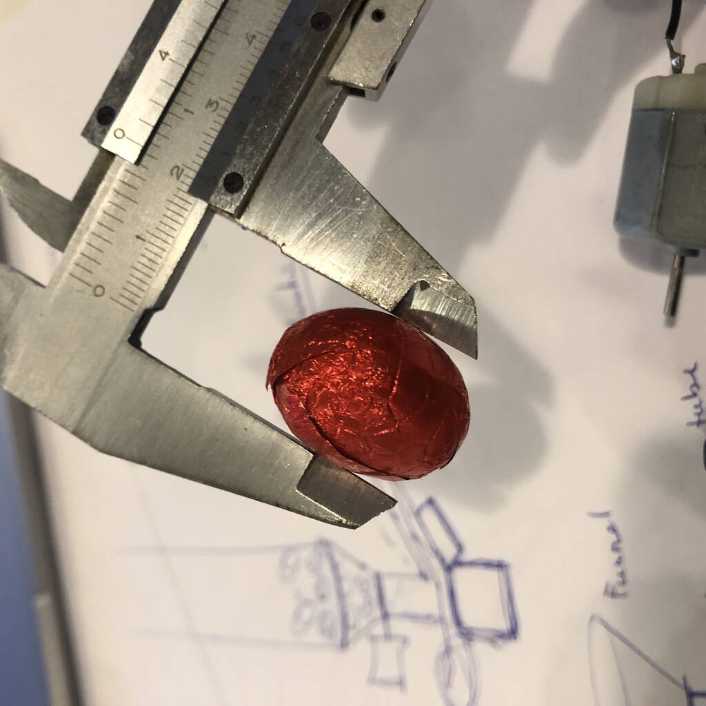
First I need the dimensions of my egg. I’ll measure the smallest diameter.
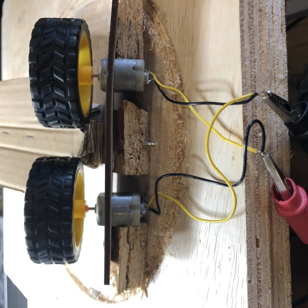
I laser cutted a little plate where the dc motors fit in with press fit. I printed two shaft couplers for the mini dc motors. I printed these little couplers with the exact same dimensions on the Prusa MKS+. It fitted perfectly.
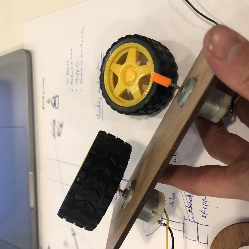
It works nice but I need to reinforce the motors so the’ll stay in place.
Let’s try if it works!
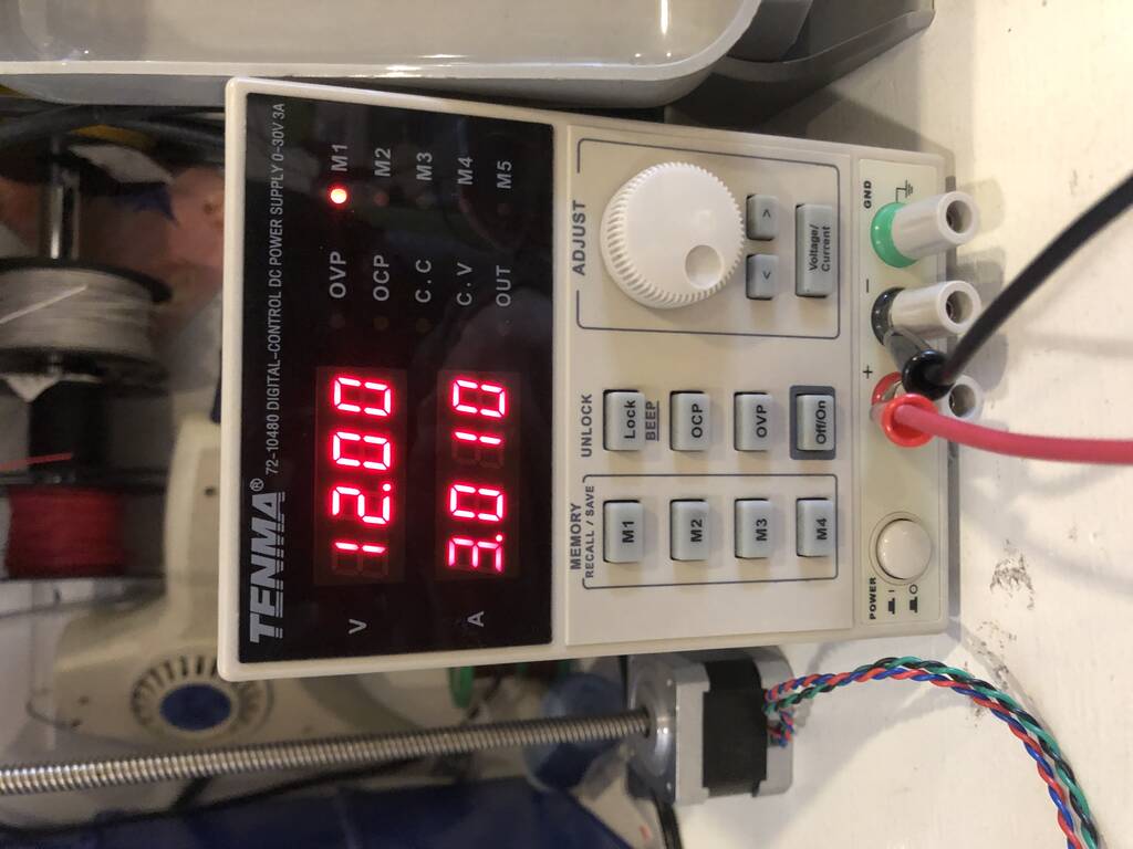
Okay okay, this is not to bad. But with some more ampere I expect a bigger BANG!
let’s try it out with a little slide.
The egg needs a little help.
I used the following code for the right push and it seems to work!
#include <Servo.h>

Servo myservo;  // create servo object to control a servo
// twelve servo objects can be created on most boards

int pos = 0;    // variable to store the servo position

void setup() {
  myservo.attach(9);  // attaches the servo on pin 9 to the servo object
}

void loop() {

  for (pos = 0; pos <= 120; pos += 1) { // goes from 0 degrees to 180 degrees
    // in steps of 1 degree
    myservo.write(pos);              // tell servo to go to position in variable 'pos'
    delay(50);                       // waits 15ms for the servo to reach the position
  }

  for (pos = 120; pos >= 0; pos -= 1) { // goes from 180 degrees to 0 degrees
    myservo.write(pos);              // tell servo to go to position in variable 'pos'
    delay(15);                       // waits 15ms for the servo to reach the position
  }

}
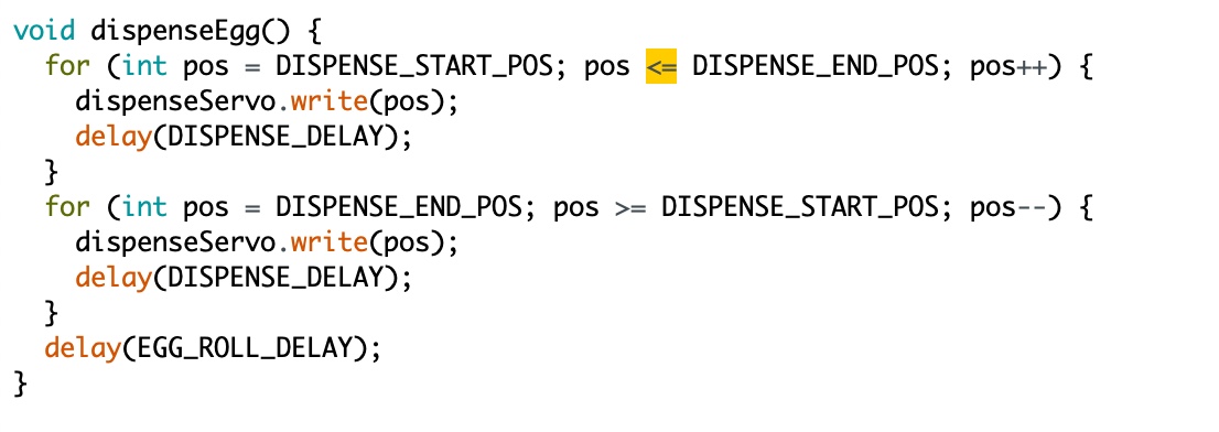
After combining the code of Michelle and mine and a vew failures later we got the right time control. It worked pretty superb.
#include <Servo.h>

int servoPin = 6;
int servoPos = 0;
int servoPin2 = 10;
int pos = 0;
Servo myServo1;
Servo myServo2;

const int inputPin = 7;  // input pin (for a pushbutton)

void setup() {
  // put your setup code here, to run once:
  Serial.begin(9600);
  myServo1.attach(servoPin);
  myServo2.attach(servoPin2);
  pinMode(inputPin, INPUT);  //declare pushbutton as input


}
void loop() {
  // put your main code here, to run repeatedly:
  int val = digitalRead(inputPin);  //read input value
  if (val == HIGH)  //check for input is HIGH
  {
    for (servoPos = 115; servoPos >= 55; servoPos--) {
      myServo1.write(servoPos);
      delay(3);
    }
    for (servoPos = 55; servoPos <= 115; servoPos++) {
      myServo1.write(servoPos);
      delay(3);
    }

      delay(20);

       for (pos = 0; pos <= 120; pos += 1) { // goes from 0 degrees to 180 degrees
       // in steps of 1 degree
       myServo2.write(pos);              // tell servo to go to position in variable 'pos'
       delay(50);                       // waits 15ms for the servo to reach the position
       }

       for (pos = 120; pos >= 0; pos -= 1) { // goes from 180 degrees to 0 degrees
       myServo2.write(pos);              // tell servo to go to position in variable 'pos'
       delay(15);                       // waits 15ms for the servo to reach the position
       }
    }
}
But after the machine was assembled with the new peripherals there were a few problems. The egg dispenser was acting strange and the the egg wasn’t shooting anymore.
First I thought that the timing wasn’t correct. But the wires of the dc motor were connected in the wrong order. Easy solve. For the servo we first posistioned it on the 0 degree angle and adjusted the direction of the equation in the code.
Turningtable
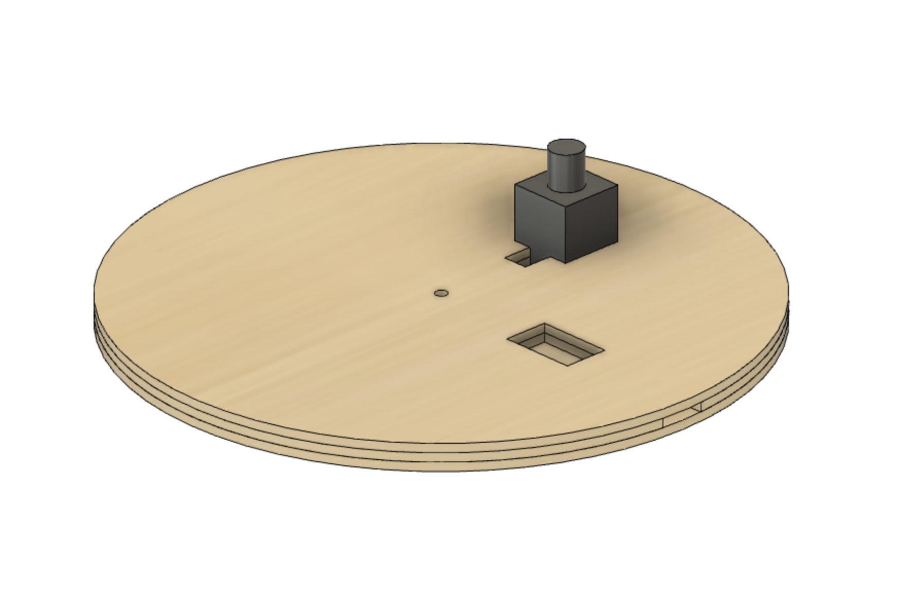
I helped Pieter a bit with the design of the turning table. We made a little design where the stepper could fit in and laser cutted the paltform with 6 mm multiplex.
We printed a few parts of the beehive machine building kid to make a similar system.
After several attempts we had some friction. But we weren’t really confident that it would work due to the lack of tension.
Here you see that the fishing thread slips away.
When we pushed the thread with some force it had enough tension so the the pulley wouldn’t slip away. But this was also proof that our way of tensioning wasn’t working out at all.
We tried different ways to wrap the thread around the middle pulley but nothing worked out as planned.
Eventually we ran out of time and Pieter decided to focus to let the turn table turn with gears.
Electronics
Michelle did a great job assembling all the individual parts together. The stepper system that she worked on was workring great.
Because I probably need this in one of my future projects. I copied a few thing out of her documentation.
For the stepper we’re using an A4988 stepper motor driver. To wire the stepper motor I copied the wiring that Pieter used which corresponds to this:

Because the stepper motor driver has integrated power regulation. This means you can just solder the power and ground directly to the 12V power supply.
This was the code that Michelle used as a test run.
/*
 *   Basic example code for controlling a stepper without library
 *
 *   by Dejan, https://howtomechatronics.com
 */

// defines pins
#define stepPin 9
#define dirPin 8

void setup() {
  // Sets the two pins as Outputs
  pinMode(stepPin,OUTPUT);
  pinMode(dirPin,OUTPUT);
}
void loop() {
  digitalWrite(dirPin,HIGH); // Enables the motor to move in a particular direction
  // Makes 200 pulses for making one full cycle rotation
  for(int x = 0; x < 800; x++) {
    digitalWrite(stepPin,HIGH);
    delayMicroseconds(700);    // by changing this time delay between the steps we can change the rotation speed
    digitalWrite(stepPin,LOW);
    delayMicroseconds(700);
  }
  delay(1000); // One second delay

  digitalWrite(dirPin,LOW); //Changes the rotations direction
  // Makes 400 pulses for making two full cycle rotation
  for(int x = 0; x < 1600; x++) {
    digitalWrite(stepPin,HIGH);
    delayMicroseconds(500);
    digitalWrite(stepPin,LOW);
    delayMicroseconds(500);
  }
  delay(1000);
}
Michelle used this [link]](chat.academany.org/landing#/fabacademy-2023/pl/pwmd3zuxctrwjkbniooyyhxcie) as a reference to work with a 8 way digital joystick to control the stepper.
This is the full code Michelle made.
#include <Servo.h>

int servoPin = 6;
int servoPos = 0;
int servoPin2 = 10;
int pos = 0;
Servo myServo1;
Servo myServo2;

int dcPin = 5;

int inputPin = 7;  // input pin for pushbutton

#define dirPin 8
#define stepPin 9

int leftPin = 16;
int rightPin = 15;
int upPin = 14;
int downPin = 17;

int leftValue = 0;
int rightValue = 0;
int upValue = 0;
int downValue = 0;


void setup() {
  // put your setup code here, to run once:
  Serial.begin(9600);
  myServo1.attach(servoPin);
  myServo2.attach(servoPin2);
  pinMode(inputPin, INPUT);  //declare pushbutton as input
  pinMode(stepPin, OUTPUT);
  pinMode(dirPin, OUTPUT);
  pinMode(leftPin, INPUT_PULLUP);
  pinMode(rightPin, INPUT_PULLUP);
  pinMode(upPin, INPUT_PULLUP);
  pinMode(downPin, INPUT_PULLUP);
  pinMode(dcPin, OUTPUT);

}
void loop() {
  // put your main code here, to run repeatedly:
  int val = digitalRead(inputPin);  //read input value
  if (val == HIGH)   { //check for input is HIGH
    digitalWrite(dcPin, HIGH);   // turn the RELAY on
    delay(3000);                     // wait for a second

    for (servoPos = 115; servoPos >= 30; servoPos--) {
      myServo1.write(servoPos);
      delay(3);
    }
    for (servoPos = 30; servoPos <= 115; servoPos++) {
      myServo1.write(servoPos);
      delay(3);
    }
    delay(20);

    for (pos = 0; pos <= 120; pos += 1) { // goes from 0 degrees to 180 degrees
      // in steps of 1 degree
      myServo2.write(pos);              // tell servo to go to position in variable 'pos'
      delay(50);                       // waits 15ms for the servo to reach the position
    }

    for (pos = 120; pos >= 0; pos -= 1) { // goes from 180 degrees to 0 degrees
      myServo2.write(pos);              // tell servo to go to position in variable 'pos'
      delay(15);                       // waits 15ms for the servo to reach the position
    }
  }
  digitalWrite(dcPin, LOW);    // turn the RELAY off

  leftValue = digitalRead(leftPin);
  rightValue = digitalRead(rightPin);
  upValue = digitalRead(upPin);
  downValue = digitalRead(downPin);

  Serial.println(leftValue);
  Serial.println(rightValue);
  Serial.println(upValue);
  Serial.println(downValue);


  if (leftValue ==  LOW) {
    digitalWrite(dirPin, HIGH); // Enables the motor to move in a particular direction

    digitalWrite(stepPin, HIGH);
    delayMicroseconds(700);    // by changing this time delay between the steps we can change the rotation speed
    digitalWrite(stepPin, LOW);
    delayMicroseconds(700);
  }
  if (rightValue ==  LOW) {
    digitalWrite(dirPin, LOW); //Changes the rotations direction
    // Makes 400 pulses for making two full cycle rotation
    digitalWrite(stepPin, HIGH);
    delayMicroseconds(500);
    digitalWrite(stepPin, LOW);
    delayMicroseconds(500);
  }
}
Pieter, our computer expert, reorganised this code on our groupdumentation.
Assembling
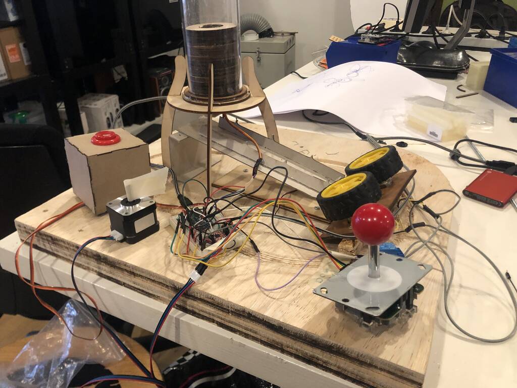
Michelle worked on the integration of all separate motors into one system, using an Arduino Mini Pro and a breadboard, and on powering the individual parts separate from a power bench.
The stepper motor and DC motors are powered by a 12V power supply and the Arduino board plus servos are powered by the computer. We also integrated a joystick to be able to rotate the future stepper platform in whatever direction you want. Here you can see the entire system working together. It’s a bit messy, but it’s a machine!
Michelle did most of the work assembling the machine together. She replaced the carboard slide for a nice plywood slide with the name of the machine on it. She did some great cable management.
How ever the cable management below the turningtable could be managed a bit better.
It all looked great in the end!
Pieter was responsible for the funny video, I made the poster Michelle finished the group documentation.
Future development possibilities
Like every living creature Patty is PERFECT! But at the Waag we always strive for more perfection. So here’s a list of a few things we would like to innovate:
-
The shooting mechanism can change in the horizontal direction but not in the vertical. We would like to add a servo that could higher or lower the shooting direction.
-
The egg dispense mechanism is not always working. Sometimes two or even three eggs slip through the dispenser. A different design for this dispenser would come in handy, we would get to fat otherwise. We’re thinking of a flapping hatch.
-
The eggs roll downwards too fast. The angle of the slide should be less steep.
-
Pieter figured out how to use bluetooth communication between two ESP Xiao boards. Next time we would like to control Patty wireless.
Group page
This is the link to our group page.