7. Computer controlled machining
Intro
This week we’ll focus on the CNC machine. We got one plywood 15 mm poplar sheet of 2500 x 1220 x ca. 15 milimeters.
Group assignment:
Complete your lab’s safety training Test runout, alignment, fixturing, speeds, feeds, materials and toolpaths for your machine Document your work to the group work page and reflect on your individual page what you learned
Individual project
Make (design+mill+assemble) something big
CNC Instructions
Machine introduction
This is Henk, our instructor, and his beloved machine.
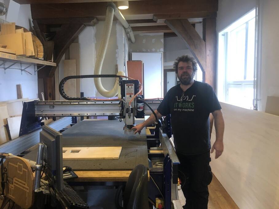
There are a lot of pay attention remarks in this intro. Henk told us that we have to do everything by our selfs so we learn how to handle this beast.
Pay attention! No leaning on the machine. Keep focus.
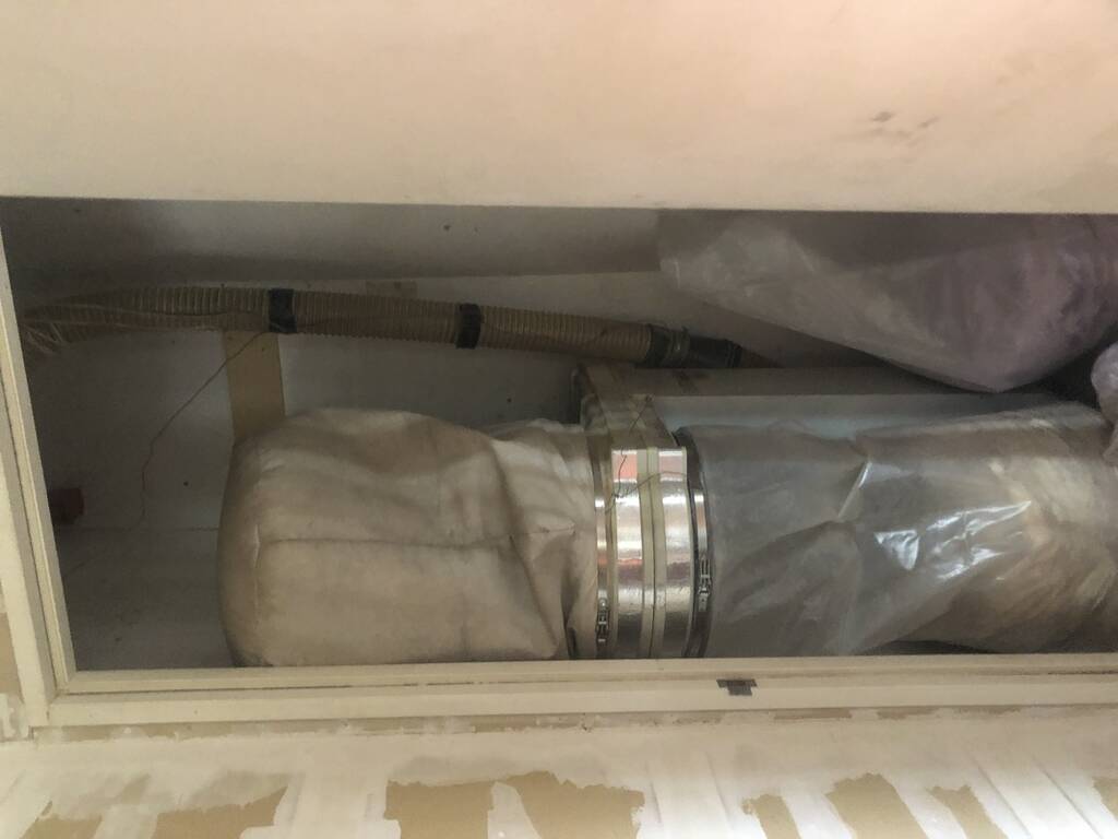
This is the dustbag with the ventilation.
We have to screw the wooden plate to the machinebed (mdf plate). If the drill touches the screw this creates sparks. Sparks will suck into the ventilation system and that can start a fire.
If screws crack in the under plate you can create a firehazardes plate for the next person.
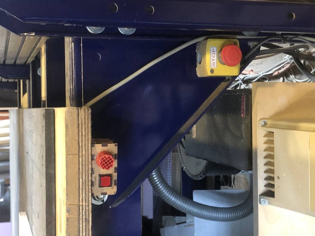
On the left the button for the ventilationsystem. Right hand button STOP button.
If you hit a screw. Hit stop button, turn of the ventilation. Check the binsack. Check for a potential fire. If you see something burning in the sack throw it out of the window!
When you pause the machine. The machine won’t move on the x/y/z axes but your spindel keeps going. Don’t leave your spindle spin in the material! This will make the material black and can cause fire.
Stay with the machine! When it’s milling.
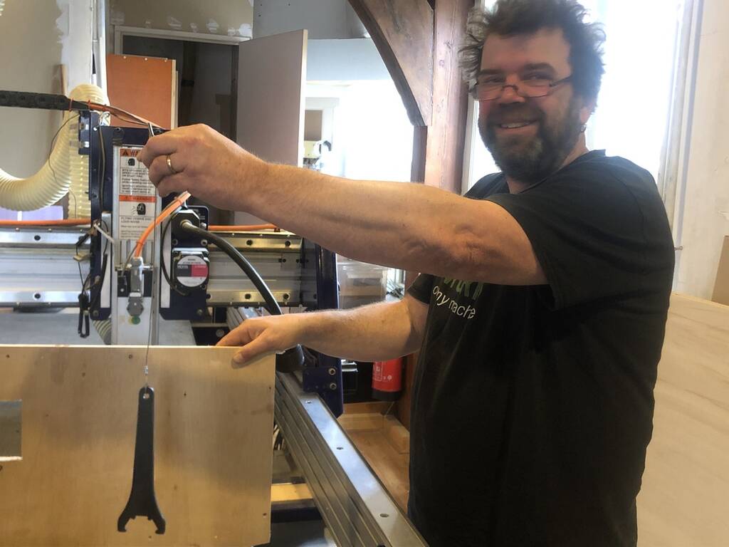
With the key you turn on the machine. With the spindle key you take out the spindle. Handy that the two are attached to each other. This prevents that you take out the spindle while its still spinning.
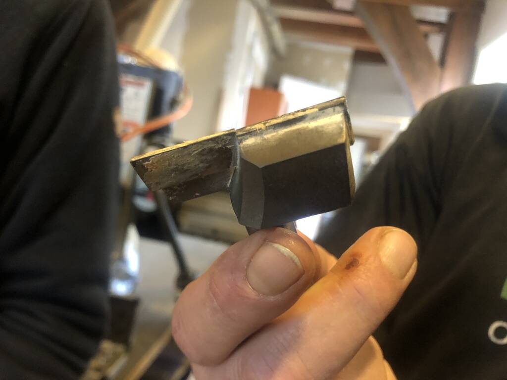
This is the collar. This holds the drill.
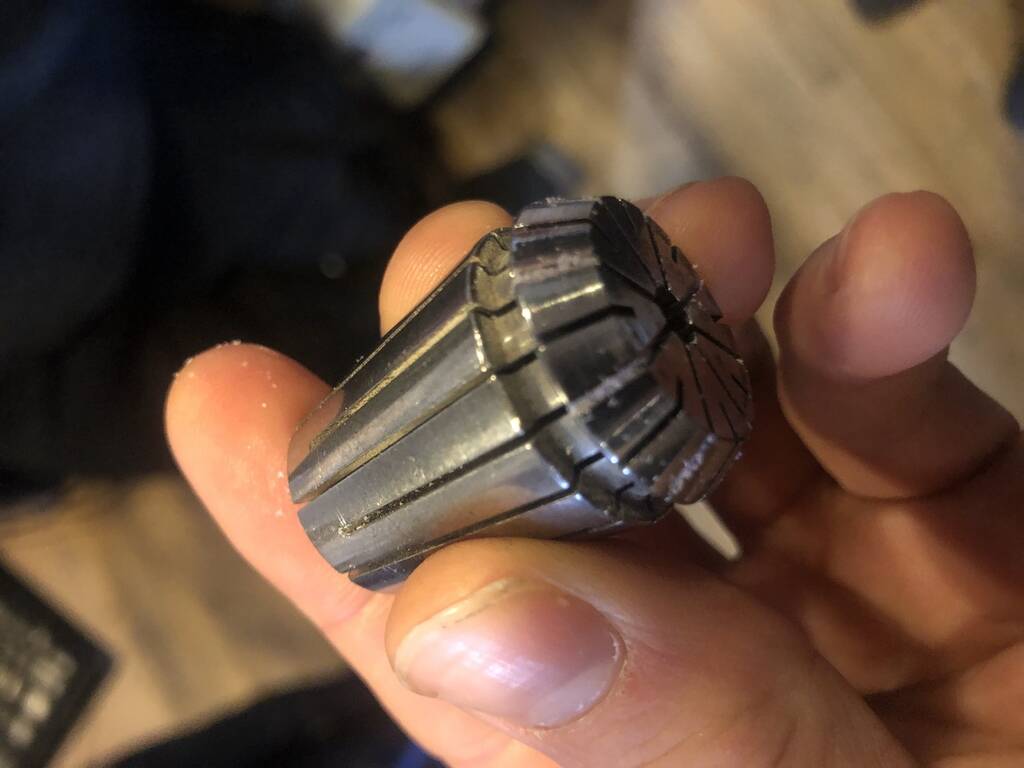
This is the clamping nut. This clamps the collar so the drill won’t fly away whille drilling. If you replace the spindle. Take out the dust of the clamping nut.
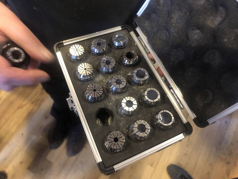
Different seizes collars. Every diameter drill bit has the same diameter collar. 5 mm bit and a 6 mm collad will be a fuck up e.g.
IMPORTANT! Collad in nut. Click! Then put screw in. Then it will be staight!
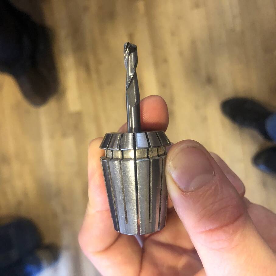
Do not put your drill to far in the collad.
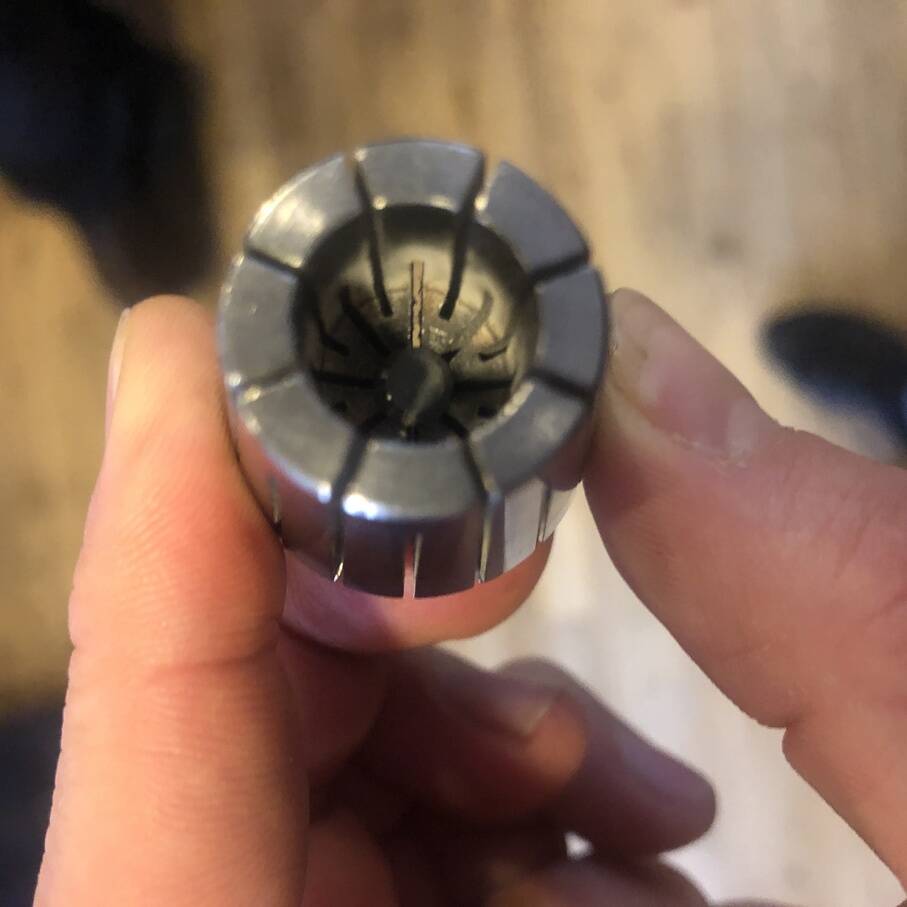
It should look like this.
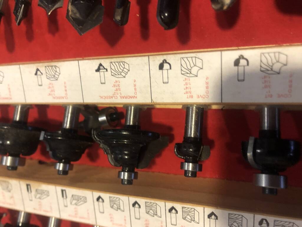
Milling bits
Thera are a lot of different mills. You can make a lot of different type of finished with this machine. For our assignment we’ll use a 5 and 6 mm two flute drillingbit.

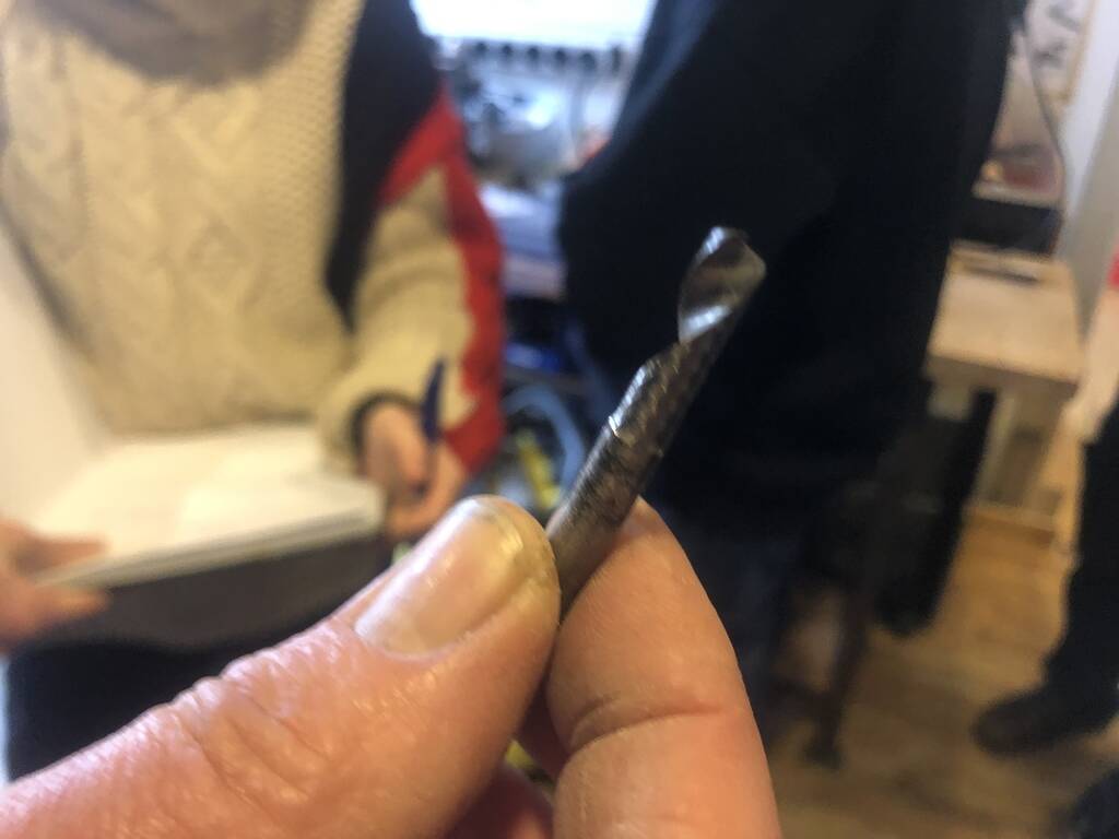
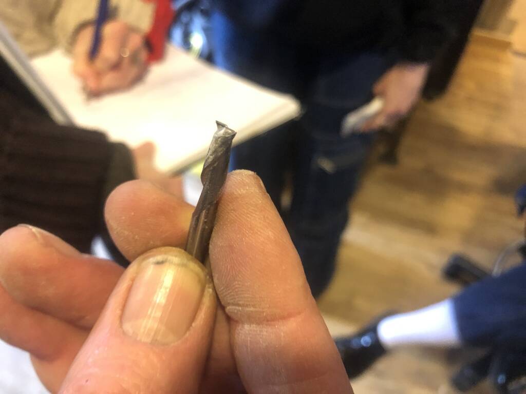
This is an one flute drilling bit. One flute has more space to collect the chipload.
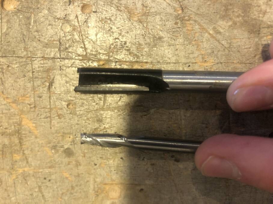
Two flute milling bits.


Climb has a better result. Climb less deep then conventional. Chip load is better. Conventional is les heavy on the machine. The material has less chance that the material wil move or effect the position of the mill.
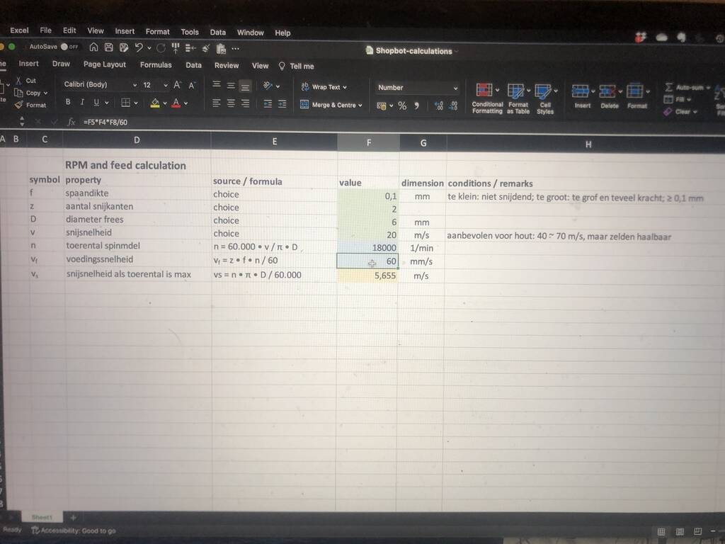
Cutting speed vs diameter drilling bit. For this assignment 6 mm.
Vf is speed rate Vc is Rotation p/m
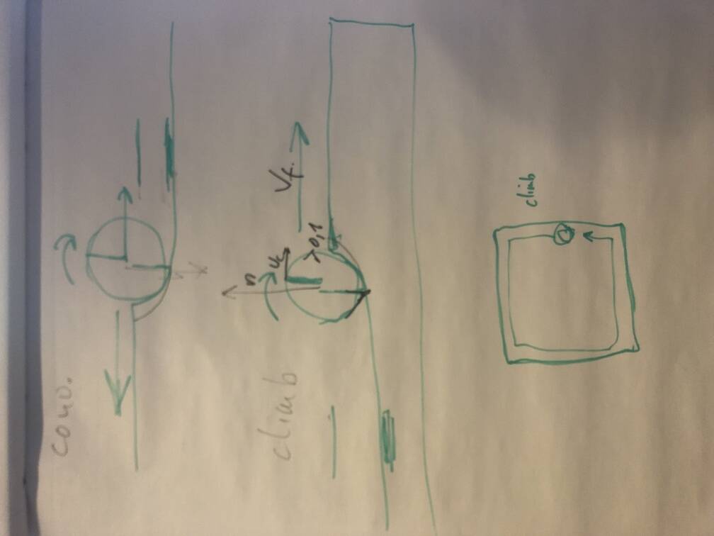
Explanation of important variables for the machine.
Vcarve
In our lab we work with Vcarve
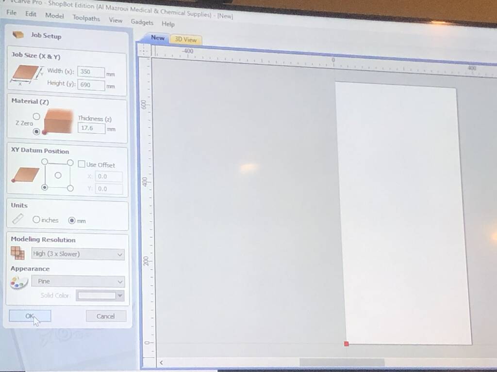
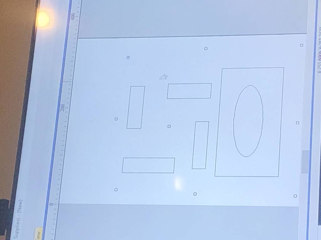
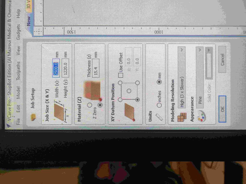
Job setup. The first important variable is the material thickness. Wood especially has a different thickness along the axes. Measure your material and go for the biggest thickness of the material to make sure that the machine will cut through.
make sure to add screw holes in your design to make sure the drill won’t cut through the screws. This can cause a firehazzard in the chipsack.
Go for a cut depht in relation to the screw head so the screw will sink in the bottomplate of the machine.
Select milling machine.
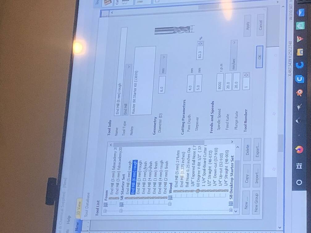
Standard settings for this machine.
- 18000 rpm
- feed rate 90
- two flute = spindle speed/100 / 2
- One flute = spindle speed/100 /4
- Plunge speed always 20/30 mm/s
The more flutes the higher the feed rate.
The step over is the radius of the drilling bit.
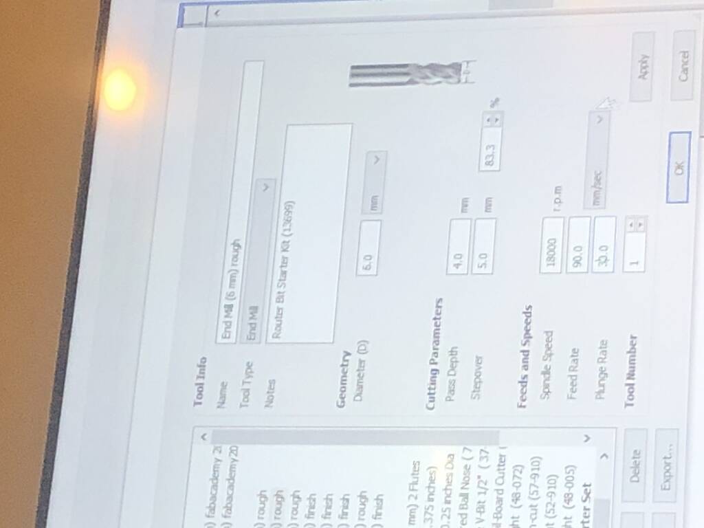
Pass depth. For two flute max 1x diameter. Start with .5 * diameter.

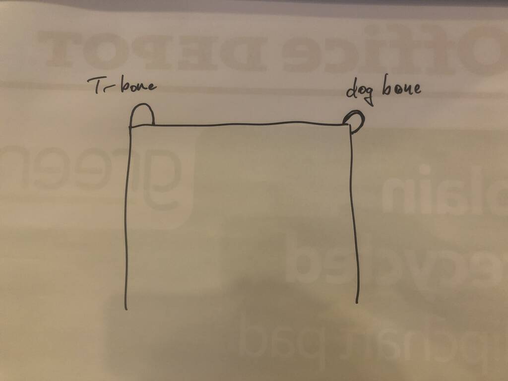
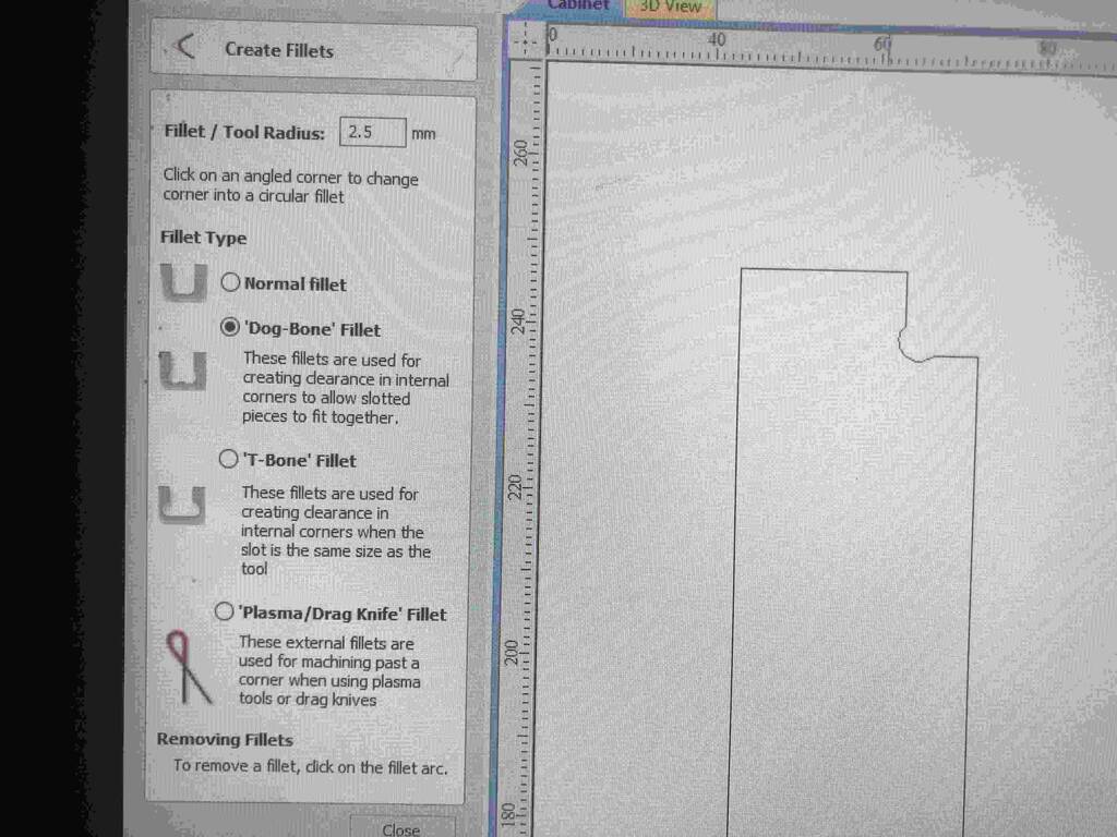
If you make an inside cut with sharp corners you need to choose between a dog bone or t-bone. The difference is an easthetic consideration.
offset for round shapes. Raster square shapes. WHAT IS HAPPENING HERE? I FORGOT..
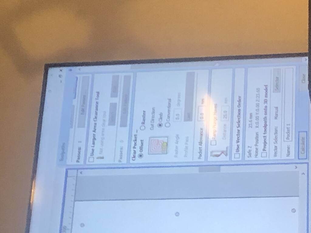
You should place tabs so the material won’t fly away when you make a cutout. IMPORTANT!
Important
Step over climb conventional feed rate one / two / four / etc, flute Pass depth Bones Tabs
Setting up the machine
0: place plate and make sure the bed is dust freen
1: Mount the drill. Check for dust
2: Place drill
3: Thigh with key tool
4: Turn on ventilation
5: Trun on machine
6: Turn on Shopbot Vcarve
7: Aluminum plate below drill
8: click on Z button in program to z level the machine
9: Hit X Y button to find the absolute XY starting point
10: Hit K to move the machine manually
11: find the relative starting point while moving the drill to your place of choiche. This is the relative staring point
12: Make a picture of this new point. You need this is when you have to push the stop button when something bad is happening
13: Turn swindle on with the key
14: Turn on ventilation
15: Load program
16: Start program hold your hand on the space bar. This will pauze the command without forgetting the x y z position
17: First drill out holes for your screws
18: turn of machine. Drill screws in. Make sure the your material won’t move
Group Assignment
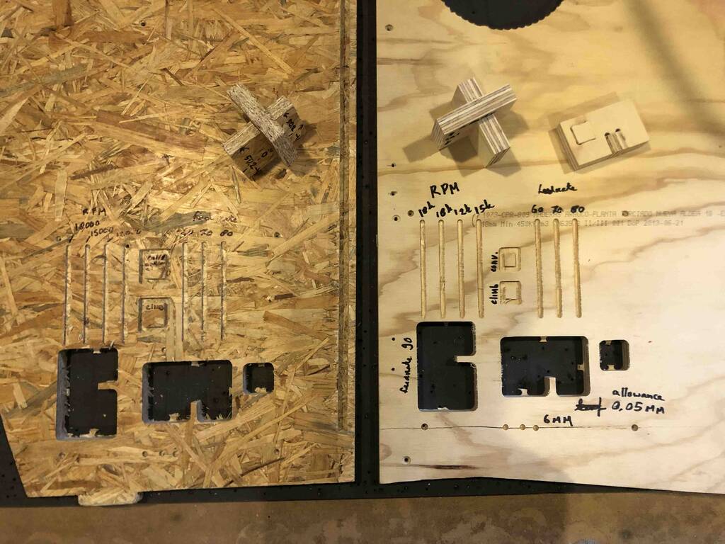
For the group assignment we did a few tests. We checked the runout, alignment, fixturing, speeds, feeds, materials and toolpaths for our machine.
Drilling bit 6mm OSB : 17,80 mm PLywood : 18,2 mm
We used different toolpaths for the different materials.
runout:
The runout is the total with of the drill minus the kerf devided by 2. Runout = drill radius - kerf / 2
Eventually we picked a line that we cut along the grain. The distance was 6,10 mm. We used a 6 mm drilling bit so this means that we have 0,05 mm runout on each side.
alignment:
We cutted out the material in a exact 45 angle.
We measured the corner with the square tool. We assumed that the square was correct. Maybe the X Y axes of the machine should kalibrated again.
fixturing:
There are multiple ways to fixture your material. At our lab we screw the material down to the botton plate of the CNC machine. First we design screw holes in Vcarce (cnc software). So we prevent the drilling bit hitting the screws.
RPM speed:
RPM is rounds per minute. We tried out different RPM speeds. 18000, 15000, 12000. For OSB, 18000 RPM works the best. For the plywood there wasn’t really a visible difference but with the OSB there was. 18.000 RPM gave the best finish, and this makes sense because the material is soft and has a lot of big fibers. If you drill with a relatively low RPM the fibers have more change to split instead of cut through.
feed rate:
The feed rate is the speed of the machine that moves in the X Y axes. We used different feed rates to see what would happen with the finish. There was know visible difference that we could match with the feed rate but the sound was terrible. Really sharp and screamy. With the previous material milled with the same feed rate worked. So we concluded that it got something to do with the material. We concluded that we will keep it with a feed rate op 60 because our Lab istructer Henk told us that was the best and savest option.
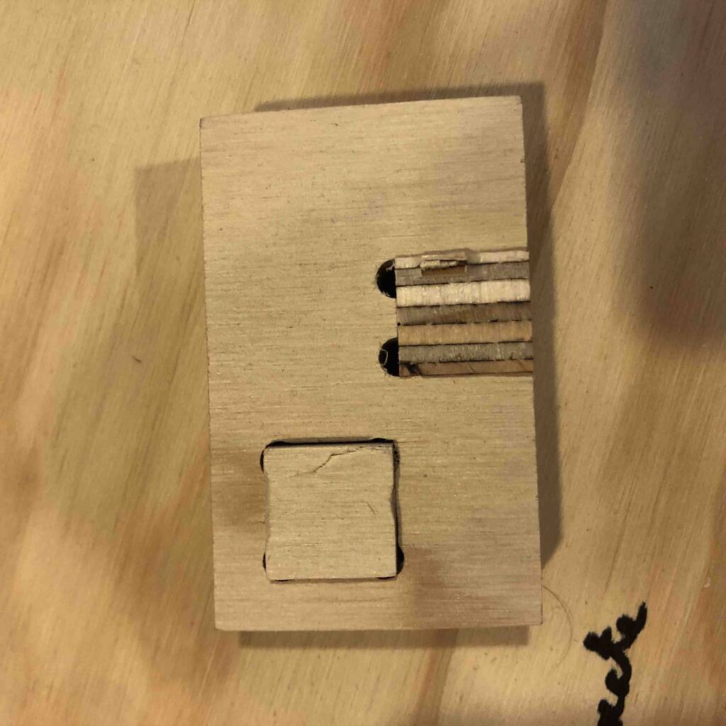
Press fit:
For the press fit we drilled a square out with the same dimensions of the thickness of the material. For the plywood this worked out great. For the OSB we forgot to adjust the dimensions. So we used a 18,2 gap for a material thickness of 17,8. This was a little too loose.

Modeling
I made several designs. Unfortunately I could machine my work because our machine failed.
Table
My first idea was to make a table. I always wanted to make a table.
Requirements
Make the table as large as possible Wheels Socket holes It should’t look like a CNC table disassemble easy
Some sketches for the table.
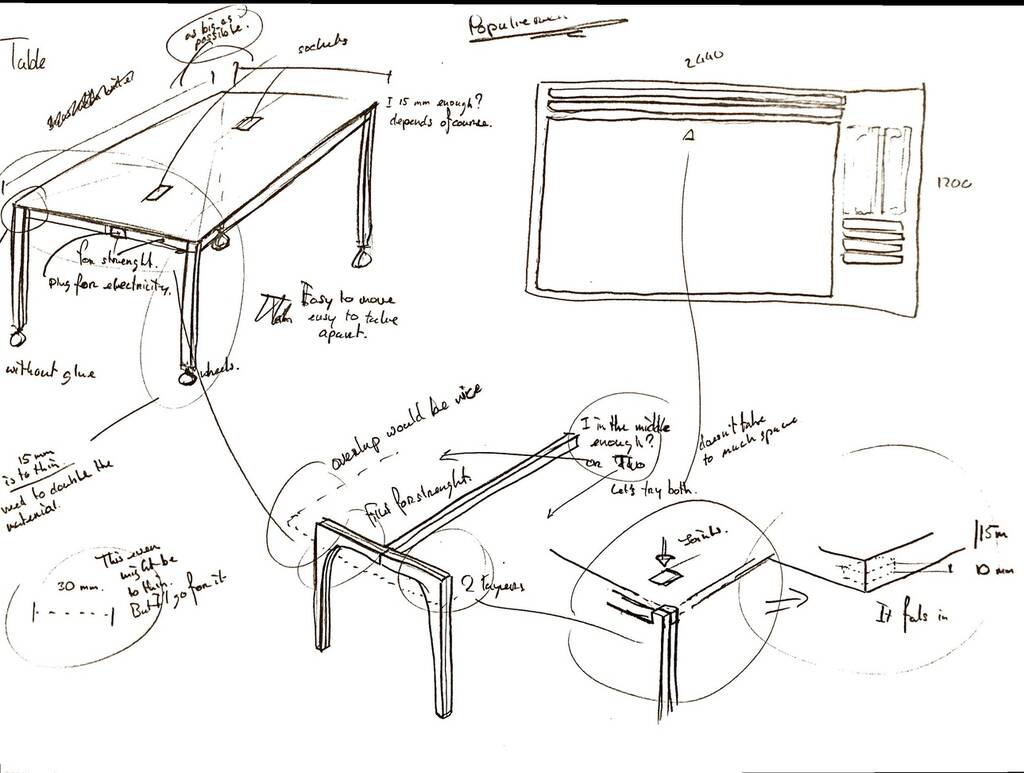
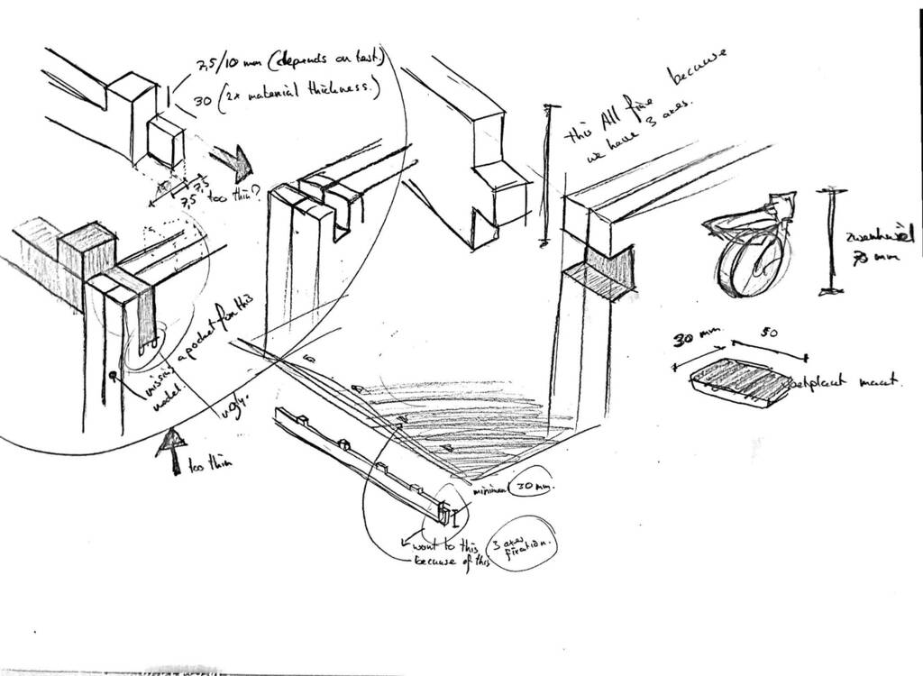
- Pockets in table 7,5/10 mm
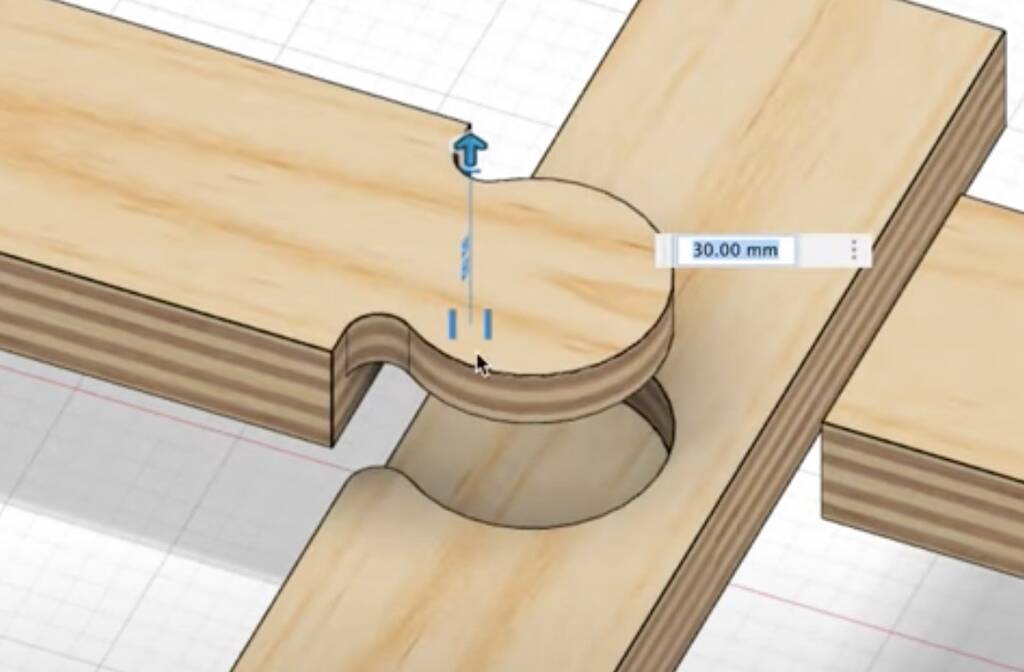
- 2 layers of material for the legs -> 30 mm
- Easy joint. Wil work because its fixaded in the x y and z axes.
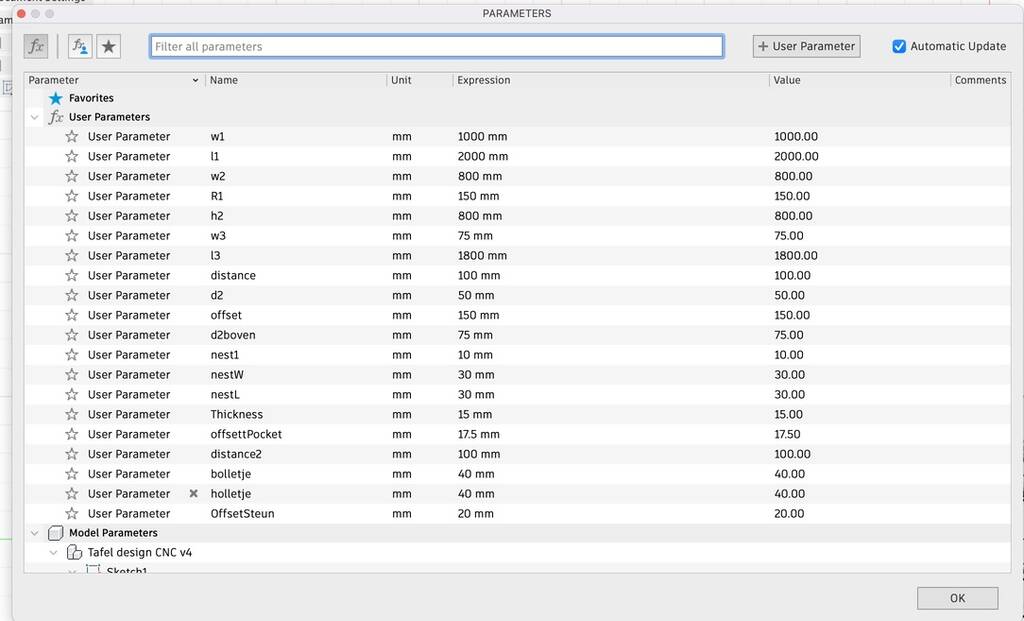
First I’ll draw everything in 2d full size. And then I’ll cut everything in pieces. I setted up some parameters so my model is easy to edit.
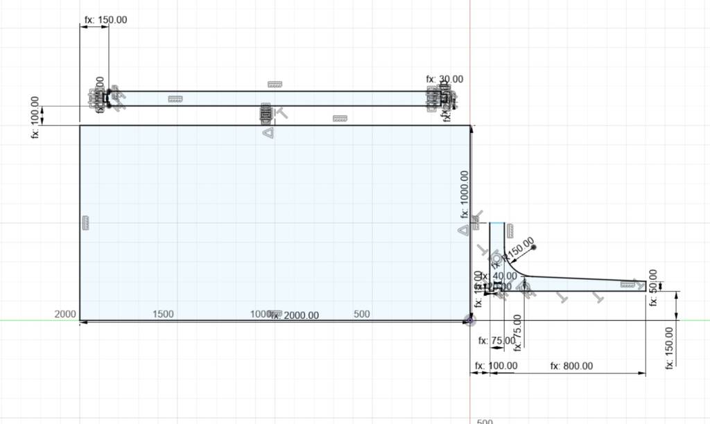
There are 3 parts that I need to cut.

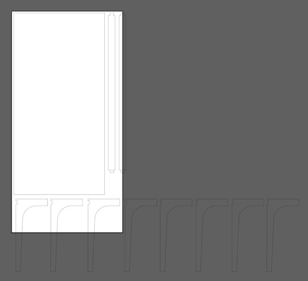
I finally decided to make something different because the table will be way too small. I know the nesting is done stupid. But I can already see that it will be to small.
Painting frames
I started with something easy.
I have a thing for put/drain covers. I like the design. I don’t know why. I paint them and then I print them on canvas.

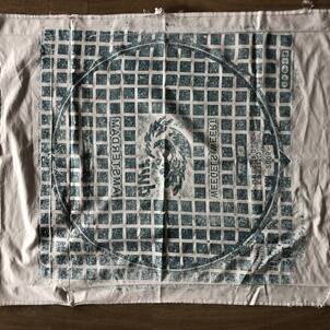
I want to make a painting frame, so the canvas will be nice streched out, with a cool joinery.
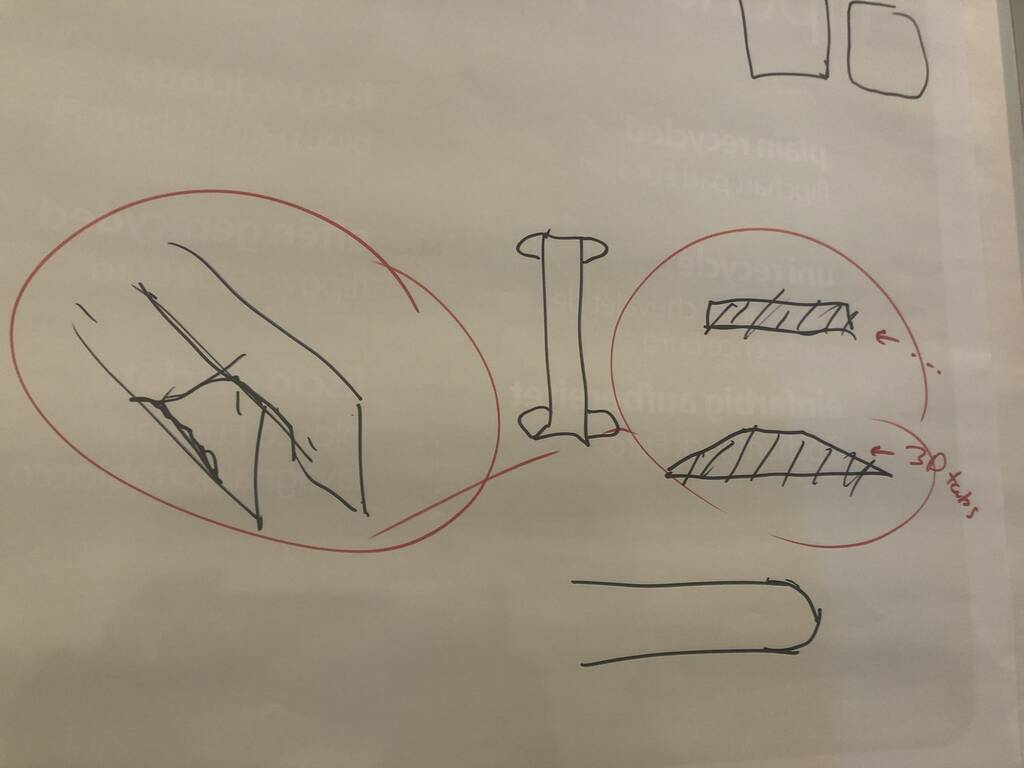
I’ll go for a few different pocket joints.

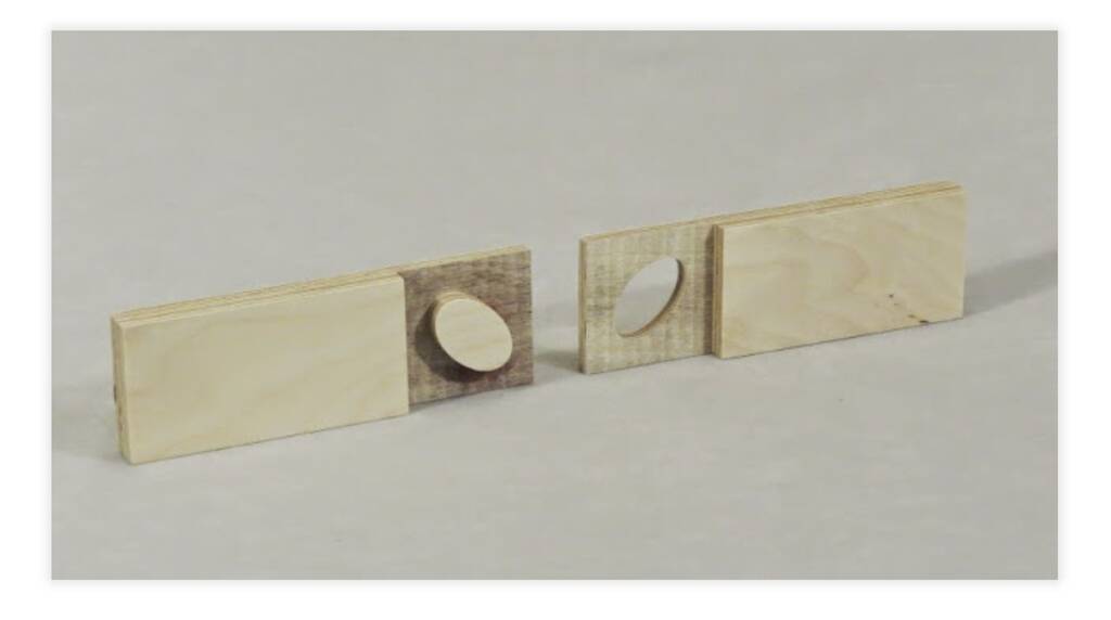
Halving with Elliptical Tenon A halving joint is one where the two parts are each thinned by half and overlap one another. The ellipse tenon in this joint provides mechanical resistance to pulling apart. This joint would be weak in hardwood because the sheer plane is parallel to the wood fibers (so called short-grain).
Double Jigsaw The two parts of this joint design are similar but are mirror images of one another.

Double Dovetail Standard dovetail shape (with rounded corners). In this joint the dovetails appear on both sides.
Oops I didn’t made components. This tutorial shows how you can change your bodies into components. Also this link shows a smart way to nest! link
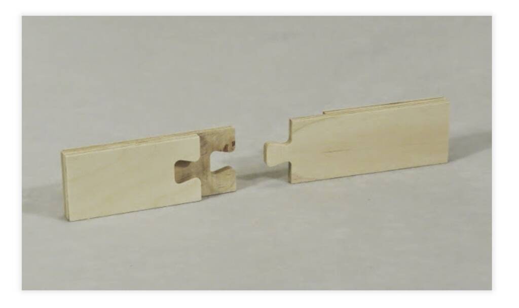
I finally used a singel dovetail joinery because I’m running out of time.
The dovetail is not the best option for the CNC machine because I need to make dog bones. This would be a joint that is more true to the proces.
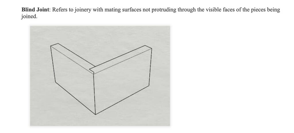
A blind joint would be super nice but that’s not possible for this weeks assignment.
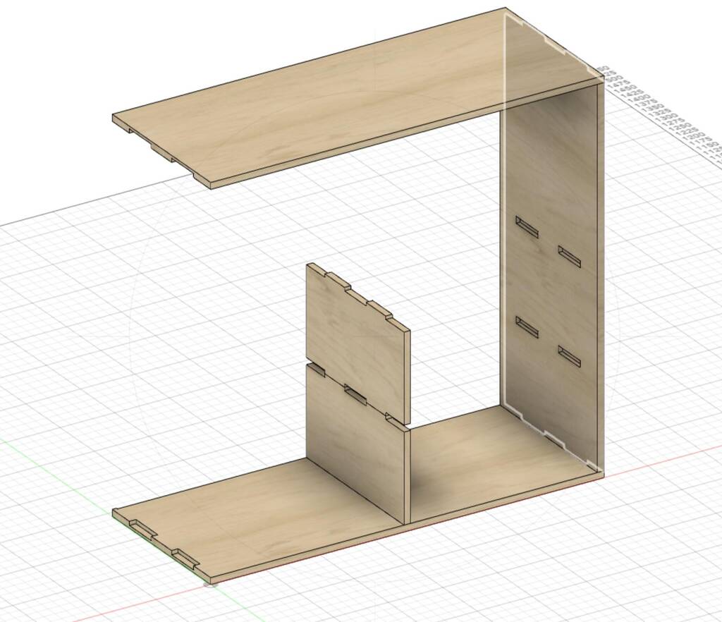
Cabinet
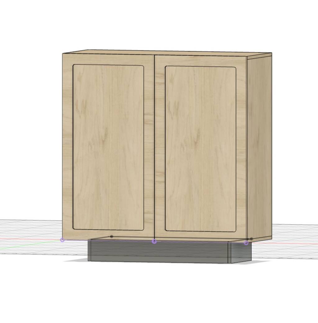
I want to make a cabinet for my entry so I’ll enter in less chaos when I enter my home.

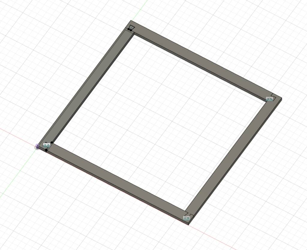
I’ve started with this cabinet. I’ve measured the place I want to place it but while modeling I was getting scared if it would fit in the plate that we’ve got.
Oops, it doesn’t look like this will fit. Dont even have my doors yet and vertical planks yet. I need to make it smaller and maybe I have to give the cabinet some legs.
Important! To spare some wood I’ll go for a cheap achterplaat of 3mm. I can change it with the parameters.
Achterplaat format -> 1140 x 745 mm <- CHANGED IT !!!!
To spare wood I’ll try to find another suitable frame to raise the hight of model and so my door can open without scratching the ground.
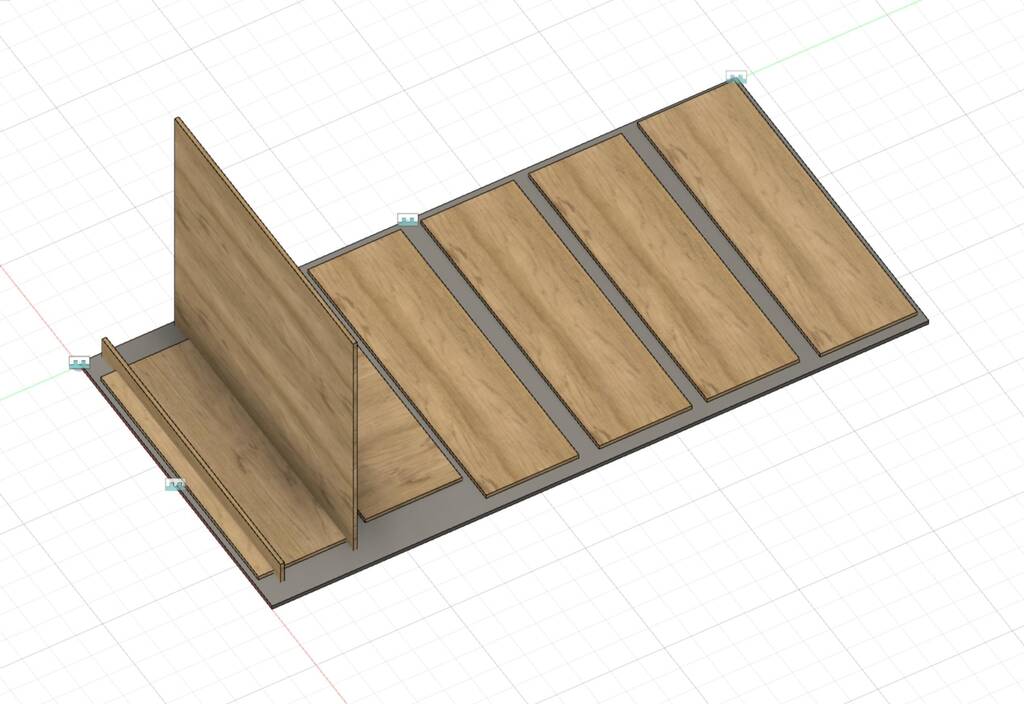
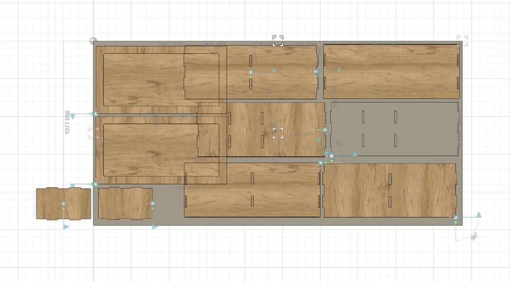
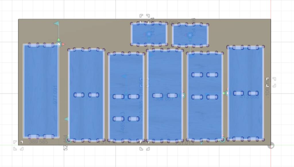
Here you see that it might will fit if I’ll do my best with nesting.

This is pretty nice though. The parameters still work when I placed them flat. Now I can see with which dimensions it will fit.
Oops it’s gonna be small cabinet.. shit.
I hope this won’t be too small.....
I might go for the cabinet without the fronts. They take too much space.
Oops I found a mistake. Since I can only dril on one side I need to adjust my model a bit. Next time I should save the bodies model so I’ll be able to edit easier.
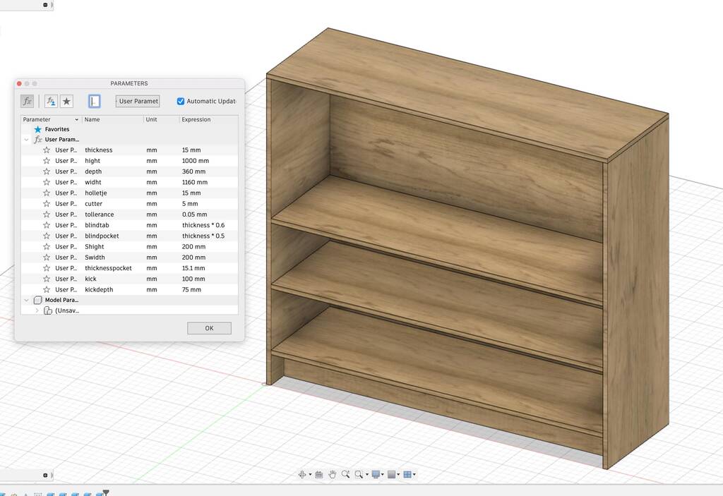
Because I modeled my model like a genius everything I edit is changing automaticaly like I want.
Exported everything in total.
Preparing for the CNC
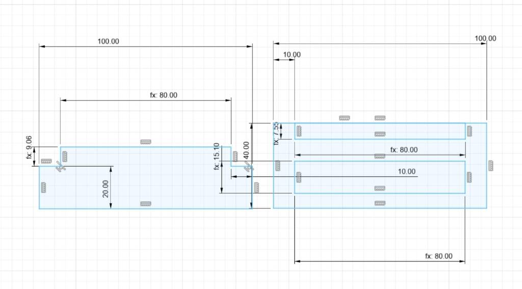
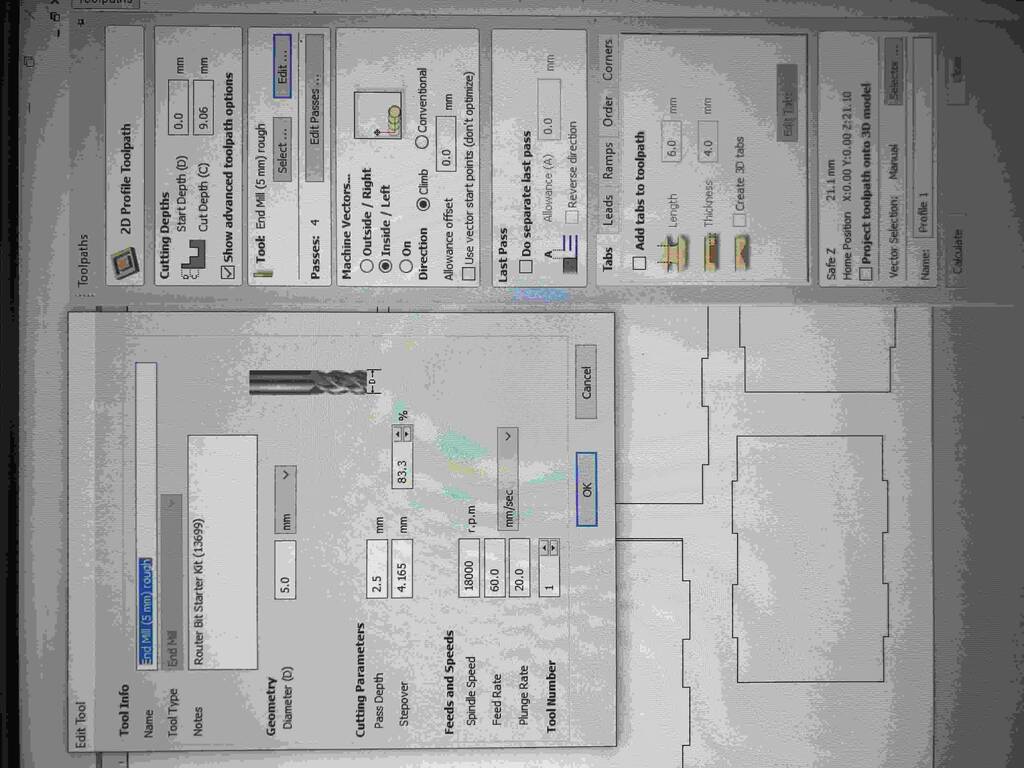
The following parameters are important:
Thickness = 15,1 / changed it to 15,25 blindtab = thickness * 0,6 = 15.1 * 0,6 = 9,06
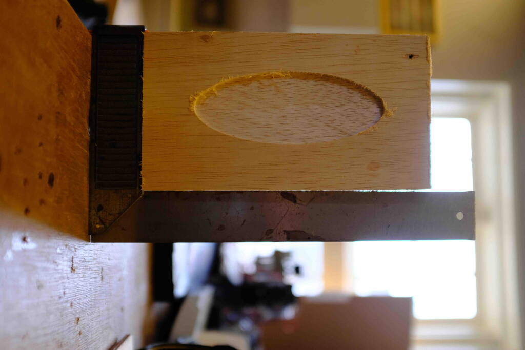
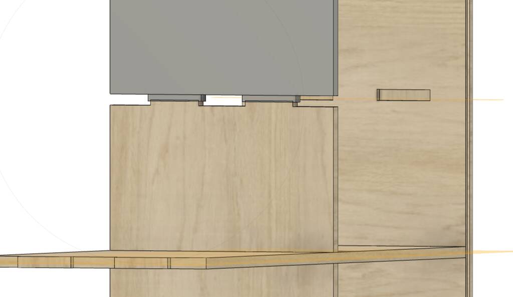
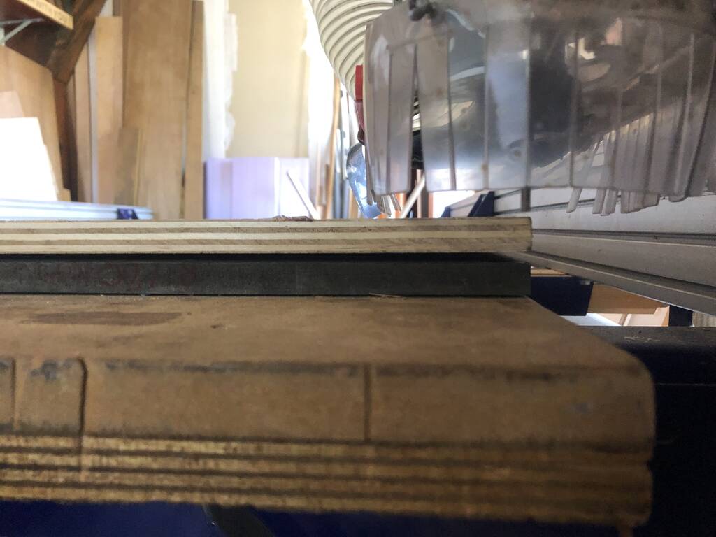
I made a little test piece to see if it will work.
I wanted a new support for the cabinet. While making the tabs for the plank I saw I did something wrong. Keep track on your parameters.
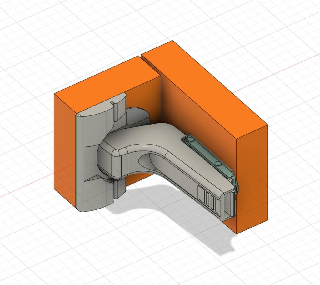
I want to use some hinges for my doors. A friend of mine send some STL files of hinges that he could get me from work.
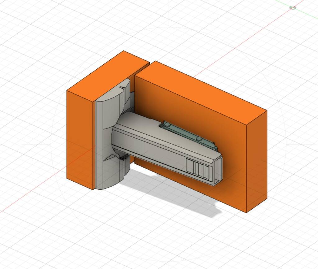
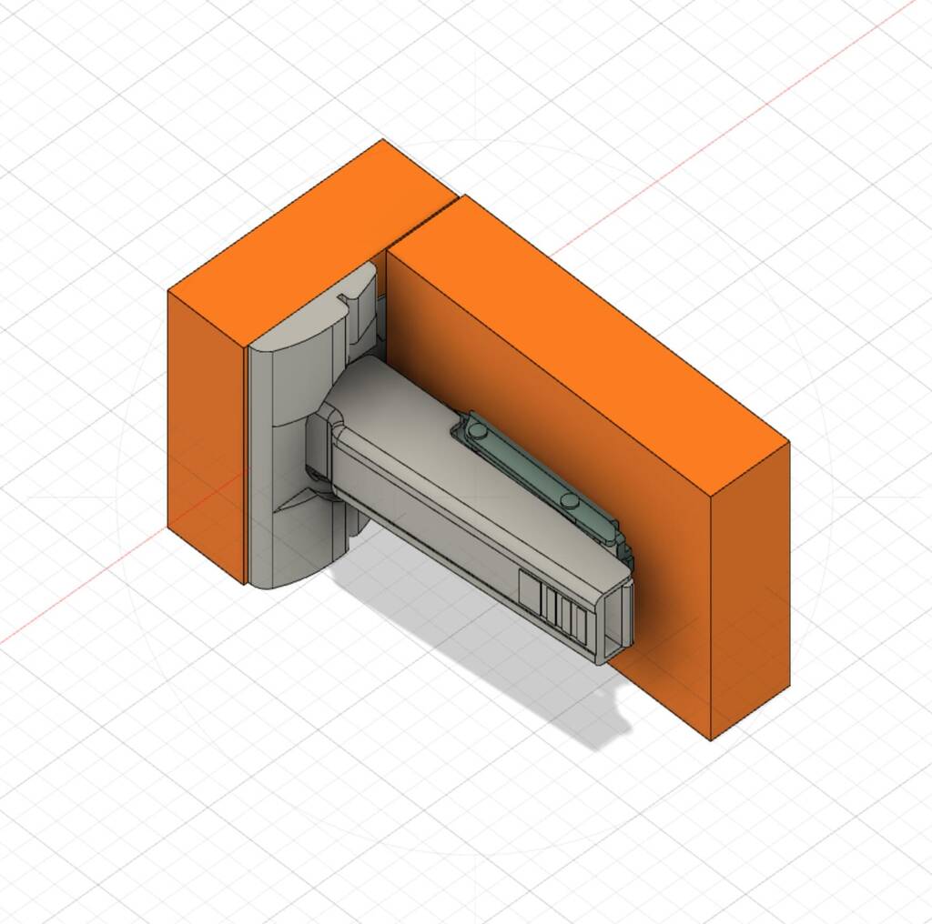
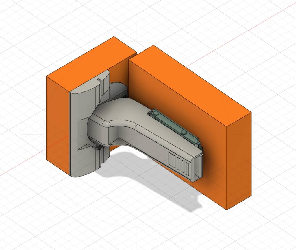
I’ll go for this ‘inliggende’.
I changed my model slightly after the machine got broken by Pieter. Pieter has a little thing for breaking things.

First setup

When importing your dxf the job size changes again.
You have to fill it in again.
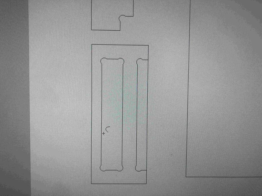
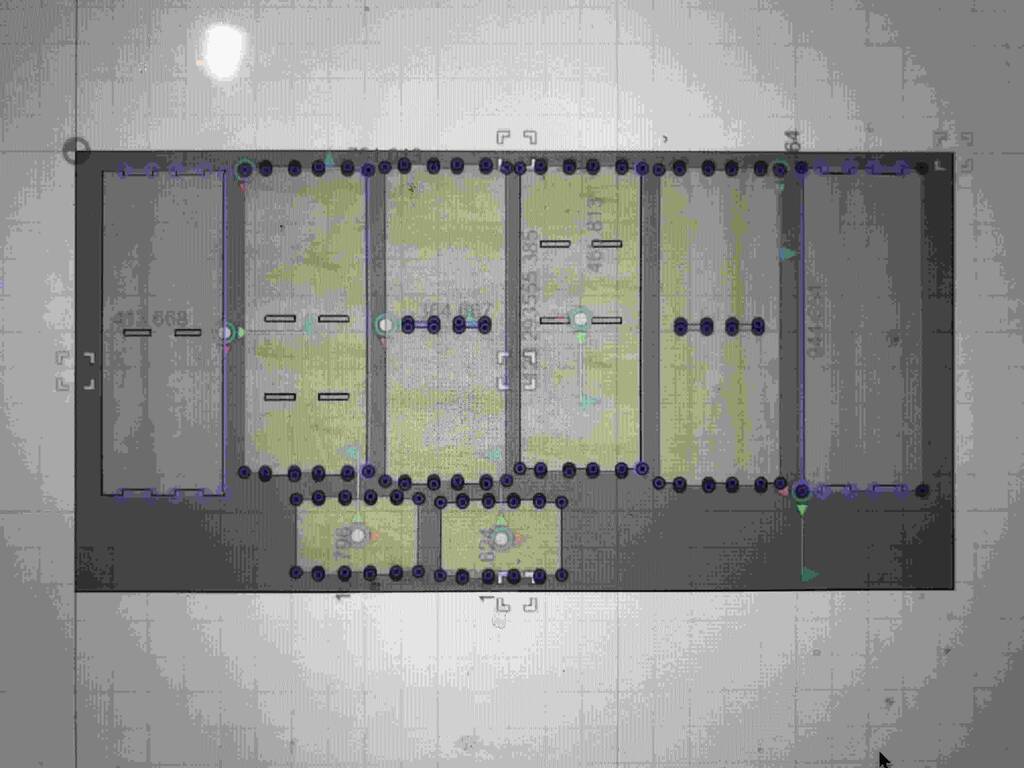
I’ll add some dogbones. But there seems to be a problem with one of the sketches….
This isn’t correct. But I think I know what is on the handje. Let me check.
This happens with the sketches that are pockets… hmmmmm.
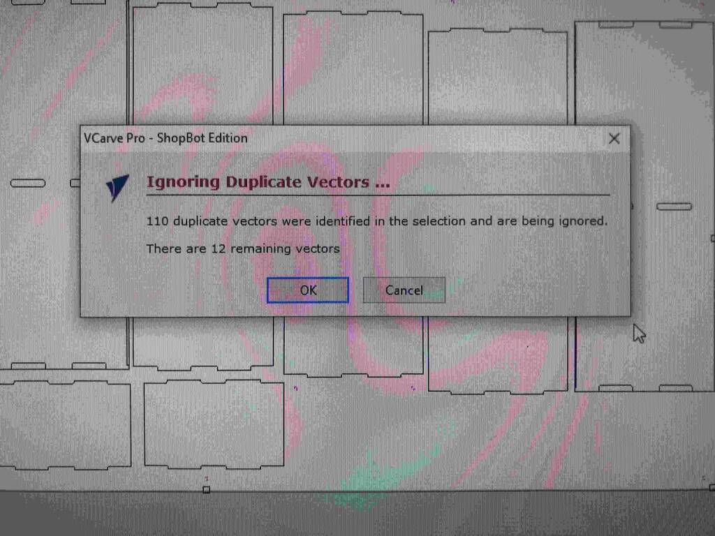
Oh shit, all my pocket lines are doubled.

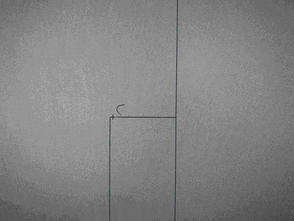
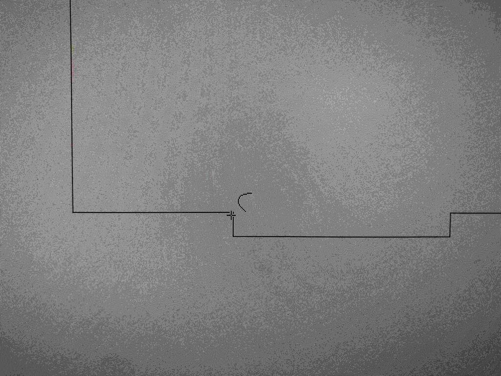
At this corner I couldn’t make a dog fillet but I had to go for a t-bone.

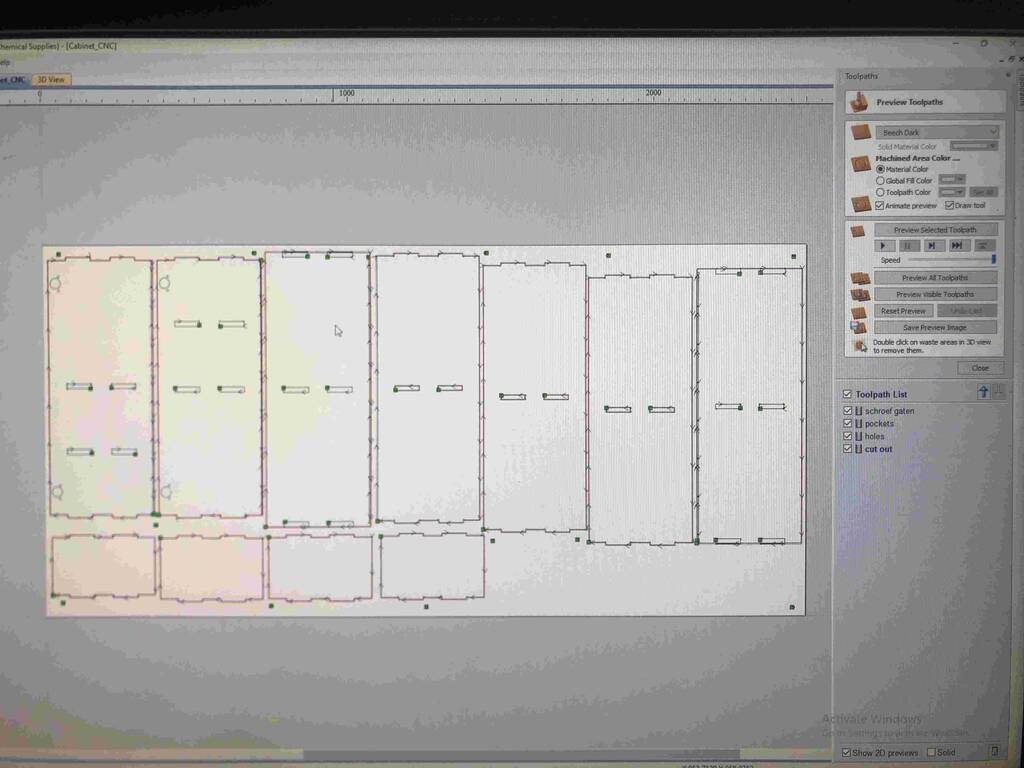
Creating my toolpath.
Trying to select a line for my toolpath. And now I see what confused me… the double lines that I just deleted are necessary of course. I need them for my pockets you dummy. I’ll import my model again. Because I’m not sure what I deleted and what not.
I need to export my sketches out fusion differently. I make one sketch with the cutouts. And one skecht for all the pockets. Then I’m able to create the right order of toolpaths.
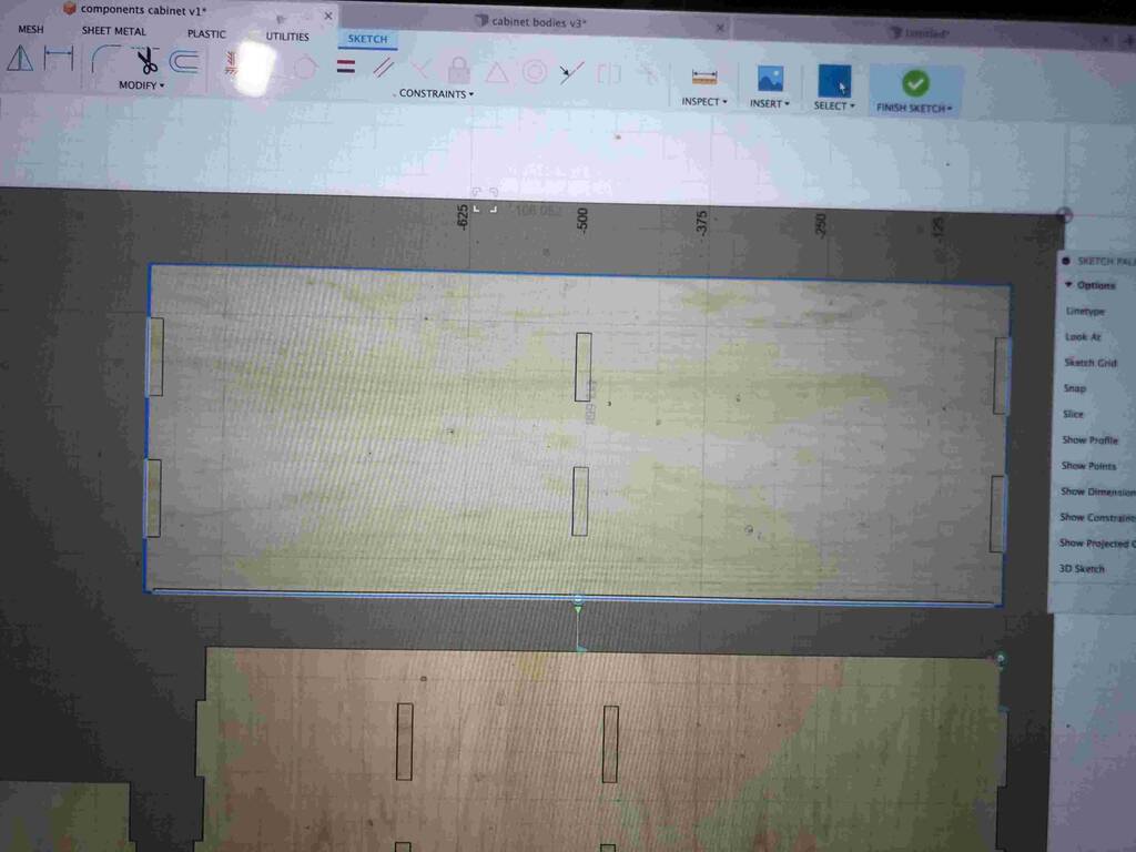
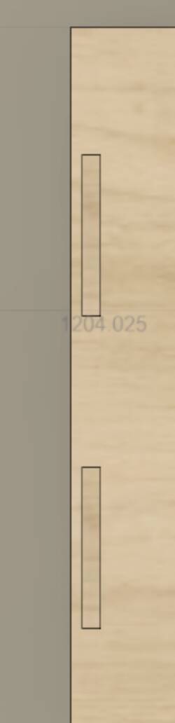
I made a sketch of all my outlines and I made a sketch of all my pockets.
First I make a toolpath for my pockets.
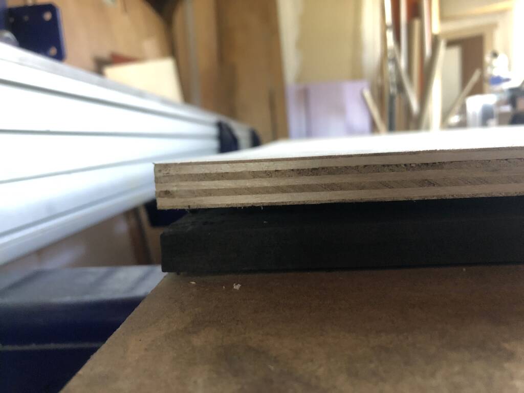
I remeasured my material. And the thickness is between 15.10 and 15.25. I’ll go for a thickness of 15.10
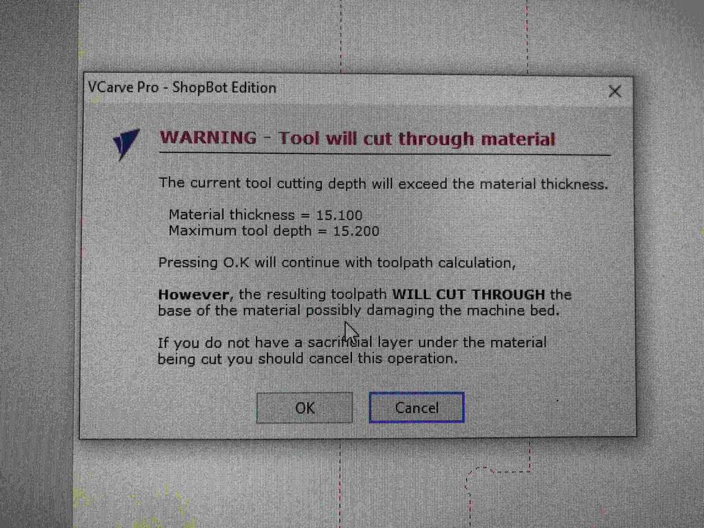
I can’t give bones here. Because my file is not grouped correctly. All the lines are individual.
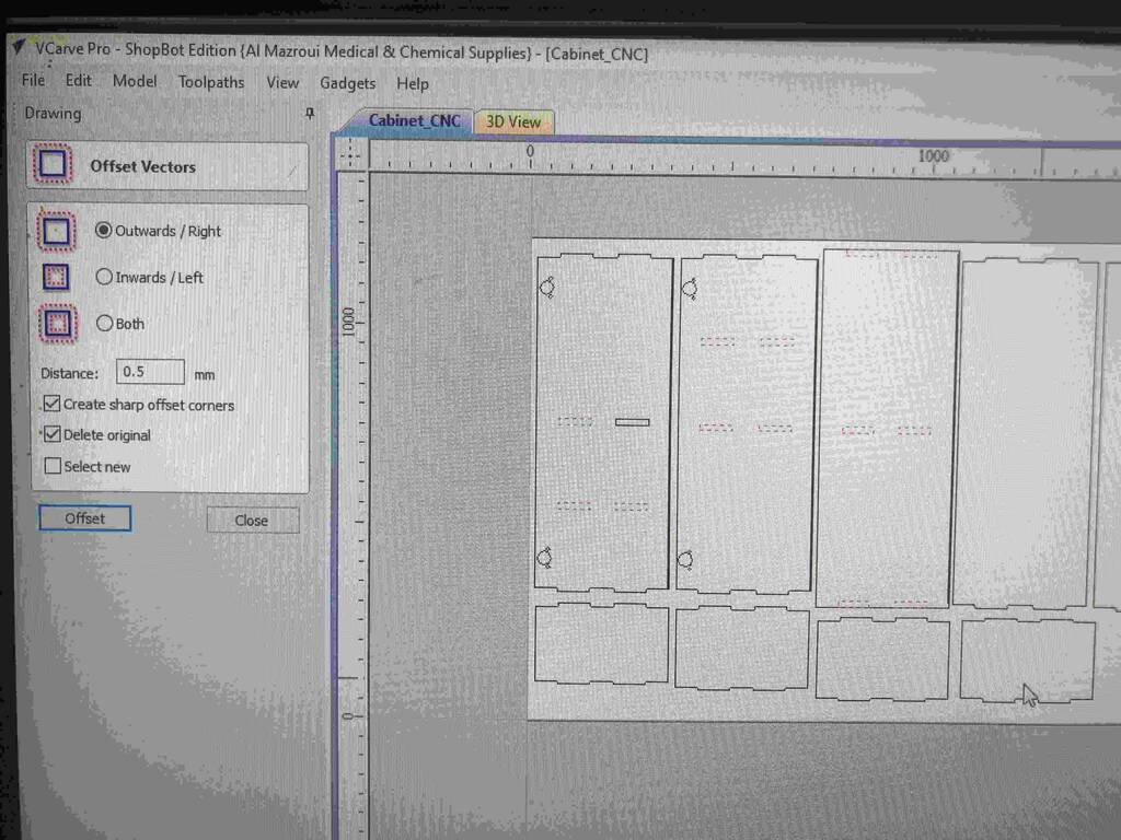
After adjusting my model and discutting with Pieter what the right offset should be I ofsetted my pockets with 0.5 mm.
I know which vectors these are. I think i shouldn’t worry about it.
Is this bad?

Okay baby!!! I’m ready for some action!!
CNC milling
Oops, the motor of the dust extractor broke down. TBC!
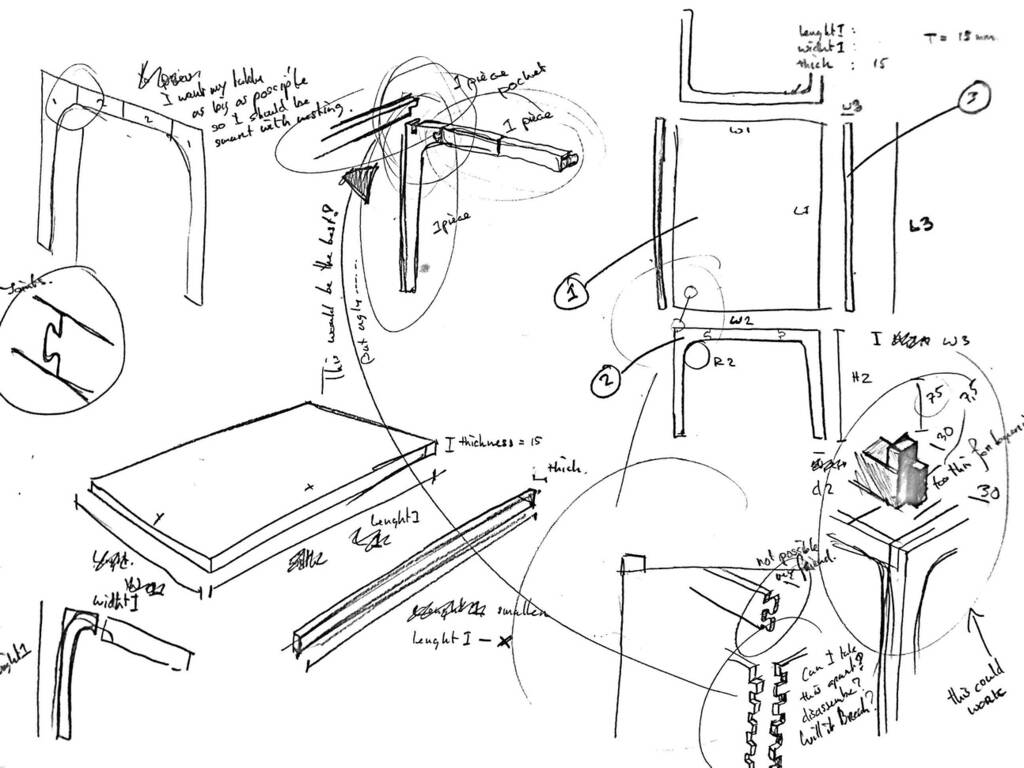
New model - Chair
I finally decided to make another model. I want something practical that I can use. The chairs I have at home are pretty old. And I think I can make something nice of the plywood material we got from the Waag.
Order model
First make sure that you make a copy of all the bodies that form the chair.
Put them in a group.
And convert them into components.
Manufacture model
Now go to the manufacture menu.
Click -> setup -> manufacturing model.
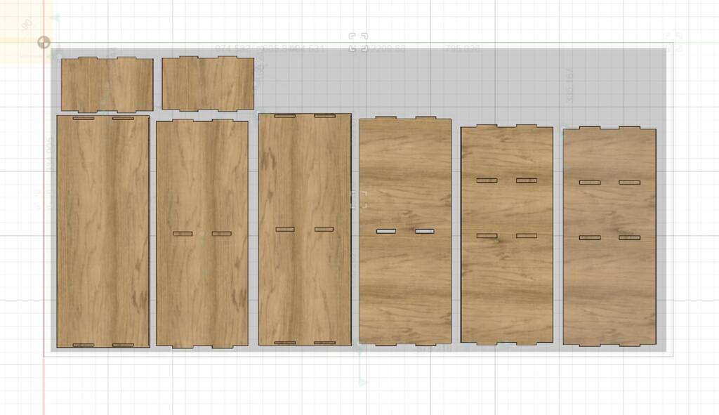
Arrange model
go to preference -> design -> enable arrange.
Also go to preview features and check -> advanced arrange.
Right click on manufacturing model -> and click edit manufacure model.
markkey select all the models (make them blue)
click -> modify -> arrange
–
if you cant find arrange take the following steps:
Click the Account user bubble in the upper right corner of Fusion 360.
Select Preferences.
Select Preview Features.
Search for “Arrange” or find Automated Arrange.
Deselect the option for Automated Arrange.
Click Apply.
Click OK.
–
Check if all the correct models are selected.
Click on envelopes - and click the face of the material that you have made in your model.
You can click the side of the model that you want to flatten if this did not already happen.
Click ok. When you have made a sketch for your envelelope and not a componennt you can make the sketch smaller to make the ultimate arrange.
You can change the frame with and the object spacing to your likely.
Tolerance/kerf
export model
Exporting models out of the manufacture mode is a pain in the ass. You need to set up set-ups and define toolpaths. At the Waag we work with Vcarve. So I’ll use another devious method that works but is not ideal.
Go in the edit manufacture model mode and make a sketch project and include via the create menu.
Finish the sketch and export as dxf by right clicking on the sketch.
Make manufacturing model
arrange parts automaticaly
How to add tollerance
Vcarve
Measure the thickness of the material. -> Mine is 15.10 - 15.30mm. So I’ll fo for 15.30 mm.
Open Vcarve. Open your your model. And adjust the material width en lenght. X and Y. Pay attention you work with the correct x and y axes.
Add screw holes in your design to make sure the drill won’t cut through the screws. Go for a cut depht in relation to the screw head so the screw will sink in the bottomplate of the machine.
Now it’s time to make toolpaths. I’ll start with the drilling toolpath. -> Select on the right hand side the drilling toolpath option.
I’ll use a cut depth of 4mm.
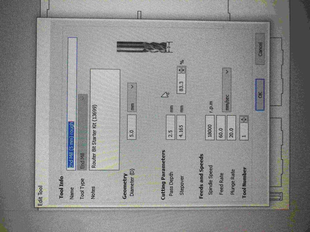
I selected the standard 5 mm tool in Vcarve.
Before we make the second toolpath we need to create some t-bones. Go to fillet in the Drawing panel. (not sure why it’s named this way).
Make sure the tool radius is in relation with the milling bit that you choose.
Not select the profile toolpath and crreate tabs. 5 and 4 mm I selected for my width and thickness.
For my model It’s necessary to go for an outside milljob and make sure to select climb.
Shopbot
Open shopbot
First Turn on Machine! Important! Otherwise you have connection problems later on.
Then press K to move the drillhead.
Check if you’re using the correct drill bit.
Now zero the machine in the x/y direction by clicking on the button x/y button in the top of your screen.
Find your new zero point in the x and y axes. Make sure the drill in a little inwards of the material and not outwards.
When you’re happy with the location clic [z]ero and zero x and y axes. make sure to make a photo of these cordinates.
Move the drill head a little towards the middel of the material and touch the drill bit with the metal plate. When you’re ready press the zero button in the top of the screen.
Now turn on the spindle.
upload your model and press start when you’re feeling confident.
Next time I should put the piece of wood the other way around. It was pretty hard to get the material flat. I made a few extra srew holes by hand. <- Watch out with this!! I eventually managed to get it flat enough.
I started the first mill job but as you see I had some leveling problems. I leveled the Z axes on the material and not on the sacrificial layer. It’s also possible to level on the material but then I should have changed settings in Vcarve.
The mill job was pretty quick. It took the Shopbot less then an hour.
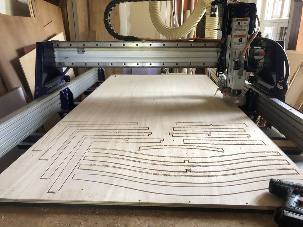
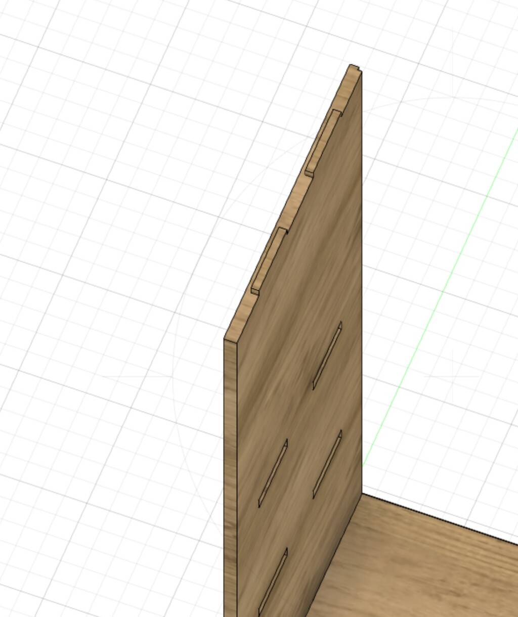
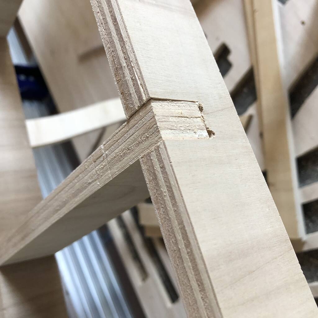
Next time I should think of the direction of the grine… Here you see that difference quite good. The long pieces should be along the grine. Think about that next time.
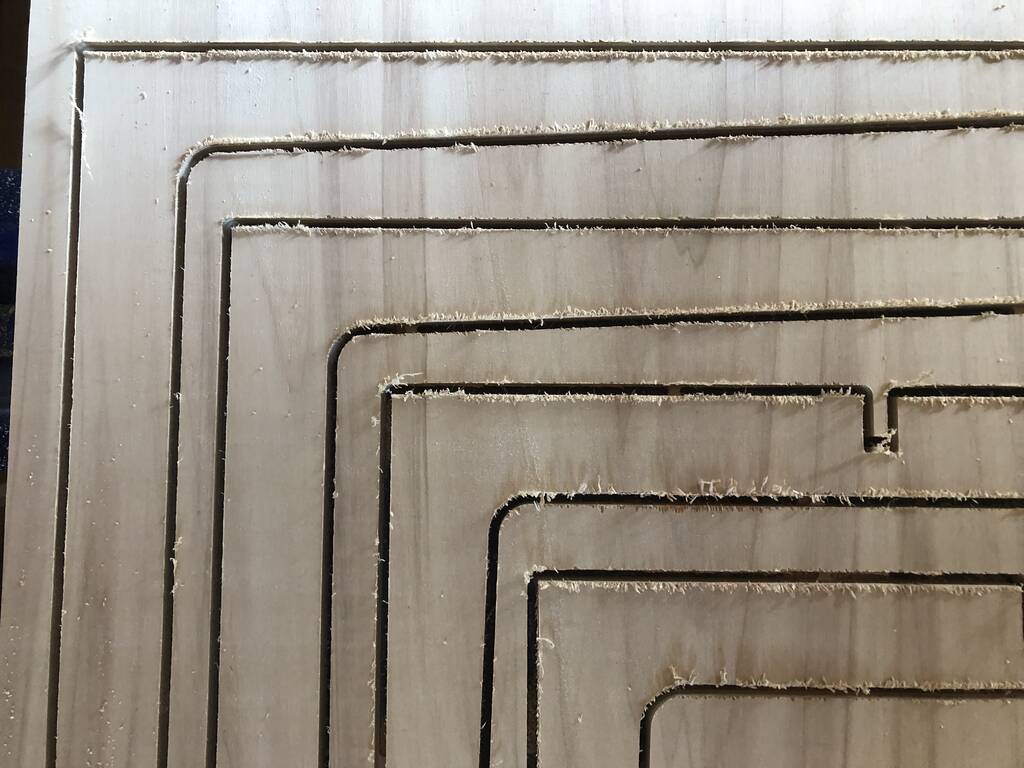
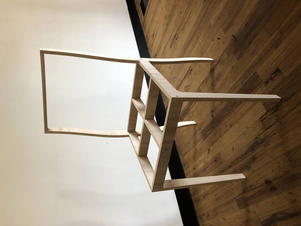
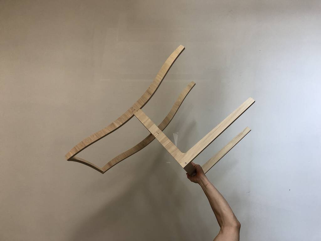
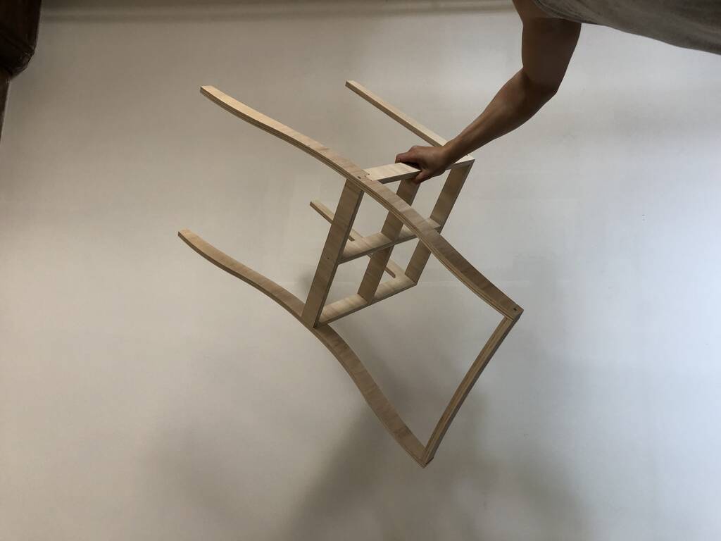
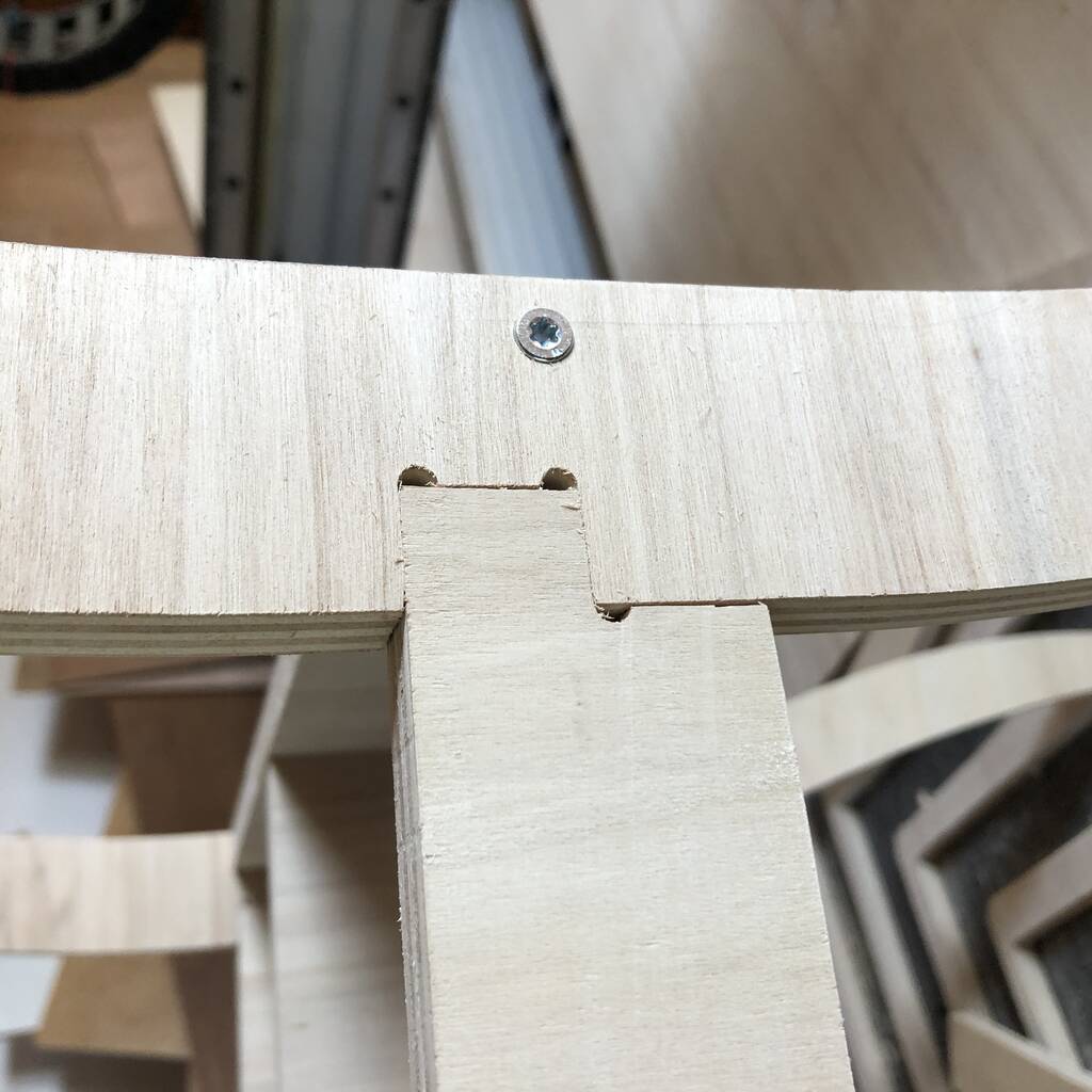
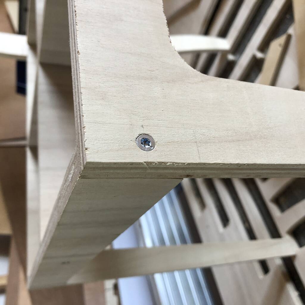
This is the result! I could assemble the chair on my own within 20 minutes. It’s not finished but it’s a nice prototype.
I used a kerf of .5 mm. Next time I would go for .4/.35. It was almost perfect.
Conclusion
This week was a lot of work. Not only with the shopbot and Vcarve, but mainly with Fusion 360. Learning a new 3d program takes a long time. I was lucky I had some experience with solidworks though. In the future I would like to see if I could setup a fusion 360 toolpath for the shopbot. That would be really cool because the workflow would be easier. Mainly because you could prototype faster and change your kerf for example without having to export and import the model in Vcarve.