3. Computer controlled cutting
Group assignment:
characterize your lasercutter’s focus, power, speed, rate,
kerf, joint clearance and types
Individual assignment:
cut something on the vinylcutter
design, lasercut, and document a parametric construction kit,
accounting for the lasercutter kerf,
which can be assembled in multiple ways,
and for extra credit include elements that aren’t flat
This week we started with the first machines. The laser cutter and the vinyl cutter. At the start of the week I thought I would spend a lot of time on the machines.......
Assignment
Group assignment: characterize your lasercutter’s focus, power, speed, rate, kerf, joint clearance and types
Individual assignment:
-
cut something on the vinylcutter
-
design, lasercut, and document a parametric PRESS FIT construction kit, accounting for the lasercutter kerf, which can be assembled in multiple ways, and for extra credit include elements that aren’t flat
Laser cutting
Henk told us we should make a lot of pictures. Let’s gooo.
What’s a laser cutter?
Laser cutting is a technology that uses a laser to vaporize materials, resulting in a cut edge. While typically used for industrial manufacturing applications, it is now used by schools, small businesses, architecture, and hobbyists. Laser cutting works by directing the output of a high-power laser most commonly through optics. The laser optics and CNC (computer numerical control) is used to direct the laser beam to the material. A commercial laser for cutting materials uses a motion control system to follow a CNC or G-code of the pattern to be cut onto the material. The focused laser beam is directed at the material, which then either melts, burns, vaporizes away, or is blown away by a jet of gas, leaving an edge with a high-quality surface finish.
Laser cutter @ the Waag
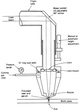
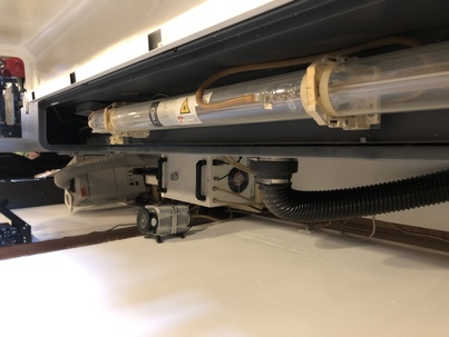
The laser machine we have in de Waag is a 100 Watt BMR 1612 CO2 laser cutter. This CO2 laser is produced in a glass tube behind the laser cutter. The laser beam travels through two mirrors from the back left to the start of the axis the laser head is located on, then through a third mirror on top of the laser head reflecting the beam down and then through the lens in the laser head. The controller board is a Ruida 644XG, which is an upgrade to the original board that came with the machine; Henk upgraded it 2 years ago.
It’s a 100 watt CO₂ laser cutting machine that uses sheet metal processing technique with a electrically driven gas laser. The laser cuts contours into metal sheet material such as steel, stainless steel or aluminium. The tube where the laser is generated is cooled with water.
On the left side you see a ventilation system that sucks the smoke out of the machine.
The laser had 3 mirrors that concentrates the laser beam so it has optimal focus and is able to cut in divers materials. Make sure the mirrors are and stay clean.
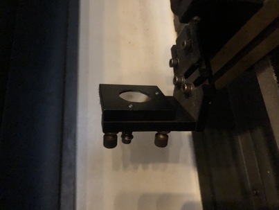
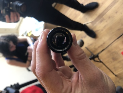
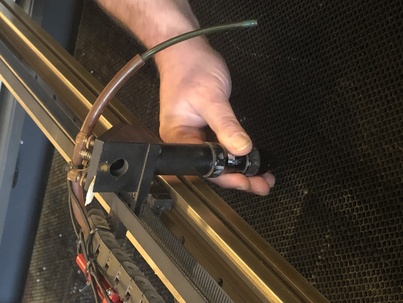
This is the lens holder, it also needs to be clean! To give you an idea: If you use the laser 8 hours per day you have to clean it once a week. You clean it whit alcohol. Alcohol evaporates easily.
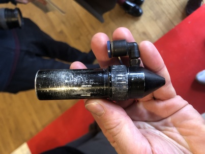
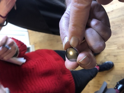
You have a confect and a concave side (conCAVE is hollow). The curved side has to be on the top so the beam is focussing in the correct direction.
You screw the lens in and out with something soft. Henk uses a at one side cut earswap.
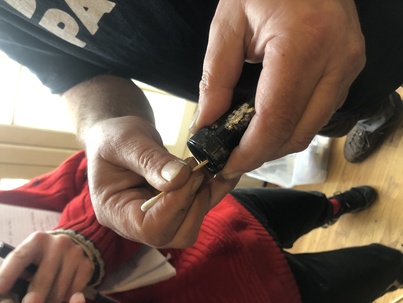
Screw it in. But not to thight so the next one can take it out.

Top of the laser. The beam. Inverse lefty loosy righty thighty.
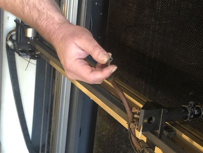
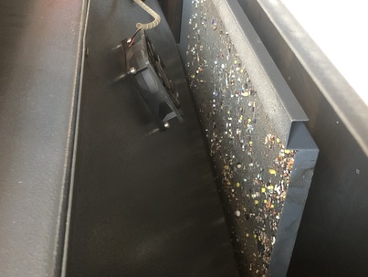
This is the Air tube. It blows the residues away so the beam has a clean piece of material during cutting.
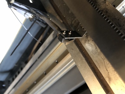
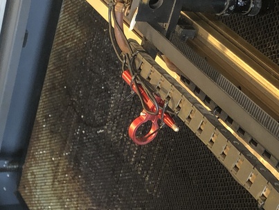
This red thing is automating the distance in the Y ax. It doesn’t work now.
The honeycomb raster makes sure that the material will stay in place and the residues will fall down.
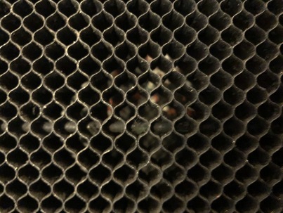
Residues.
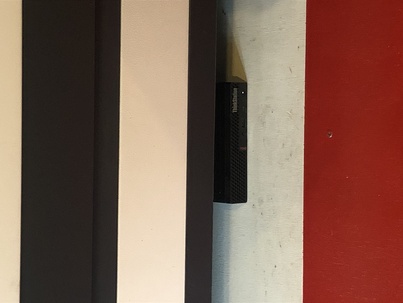
The computer that drives the machine is underneath the cutter.
On the right hand side of the machine there are a couple of switches. Switch it on with the key and use the green button. Follow the numbers. Eeeeeasy.
When it’s booted the laser goes to the end stop (top right) and then it goes back to the last position.
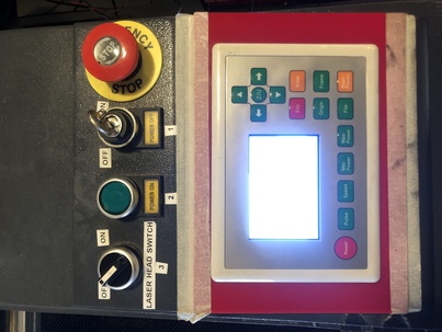
Only use the panel on the right hand side to the turn the machine on. Try to work as much as you can on the display computer.
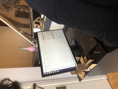
Use the arrows to move the beam.

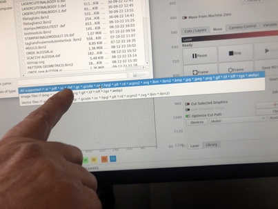
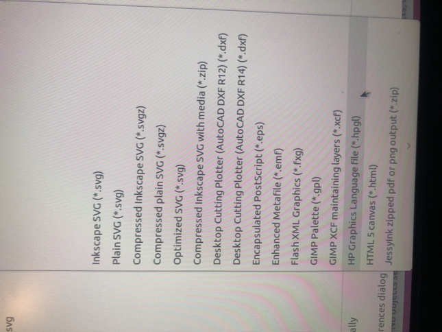
Here you can see all the formats that you can import. For example if you use Inkscape you export and import svg.
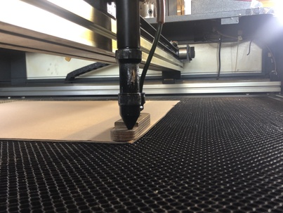
Today we’ll use cardboard. Cardboard is cheap and easy in use. Good for prototyping.

Think of where you make your test cut. Dont waste material.

This is the height!!! You can move the beam up and down by hand.
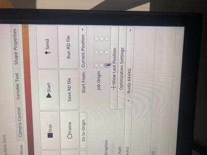
Leave the job origin on the lower left bottom of the material. Check on the computer display if the same origin is in place!
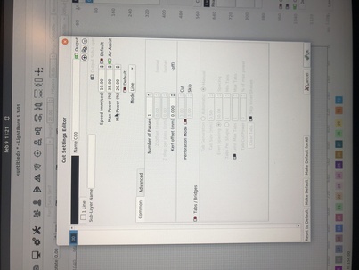
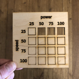
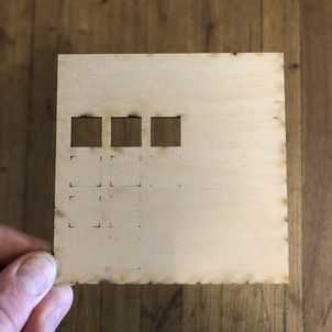
The little chard tells us what the correct combination of power and speed is to cut or ingrave in your material of choice.
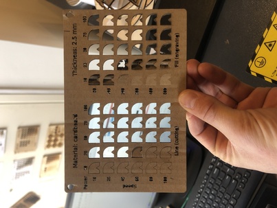
Power and speed speaks for itself. The ‘’min power’’ is the power used when for corners. Air assist always toggled on! (Green). Except really thin and lite materials. Cause the material can fly away.
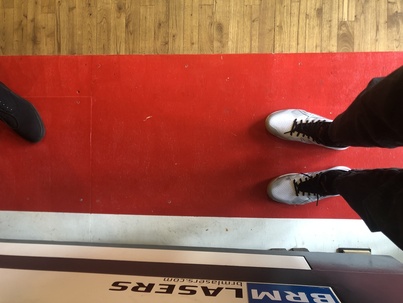
When the machine is cutting you are not aloud to leave the red space.
Plug in plug to activate the ventilation system.
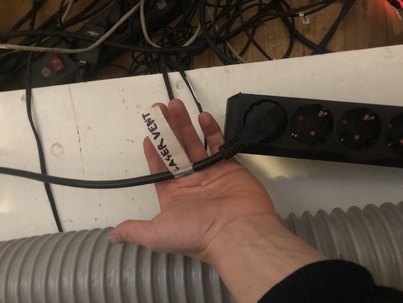
This is the ventilation system. It’s on the correct setting!
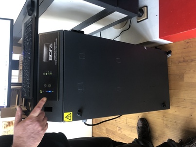
The top filter is for big particals. Down filter is a HEPA filter for small particals. HEPA filters are also in Corona masks to give you an idea.

When the ventilation is on, machine on, and the origin is set you turn the laser on (number 3) on the machine display.
Cool piece of cut material;)
Vinyl cutter
A vinyl cutter is an entry level machine for making signs. Computer designed vector files with patterns and letters are directly cut on the roll of vinyl which is mounted and fed into the vinyl cutter through USB or serial cable. Vinyl cutters are mainly used to make signs, banners and advertisements. Advertisements seen on automobiles and vans are often made with vinyl cut letters. While these machines were designed for cutting vinyl, they can also cut through computer and specialty papers, as well as thicker items like thin sheets of magnet. In addition to sign business, vinyl cutters are commonly used for apparel decoration. To decorate apparel, a vector design needs to be cut in mirror image, weeded, and then heat applied using a commercial heat press or a hand iron for home use. Some businesses use their vinyl cutter to produce both signs and custom apparel. Many crafters also have vinyl cutters for home use. These require little maintenance and the vinyl can be bought in bulk relatively cheaply. Vinyl cutters are also often used by stencil artists to create single use or reusable stencil art and lettering
At the Waag we have two cutters, the Cricut and the Roland GX-GS vynil cutter.
The machine has a couple of wheels. You can freely place the wheels as long as they are in line with the white stripes.
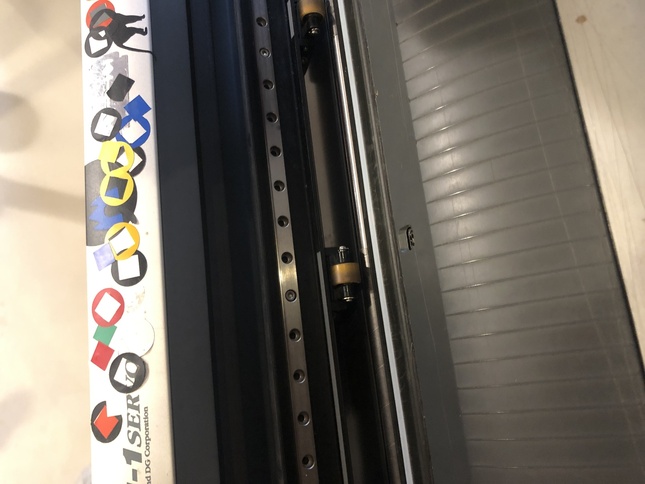
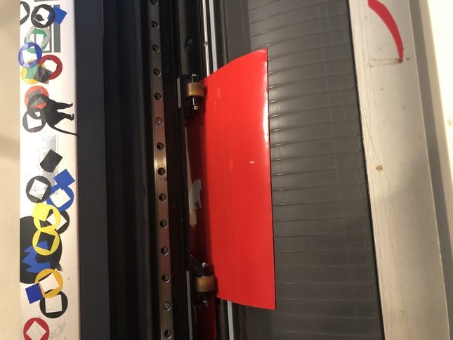
Place the material within at least two wheels guides.
Select the right option for your material roll.
Roll is for a ’infinite’’ roll of material.
Piece is for a relatively small piece of material. When you select this option the machine measures the length of the material by rolling it to the end and back to the start.
Edge I don’t know yet
When the wanted design is cut and your design has ‘’islands’’ protecting tape is used to peel the sticker of and place it on your object.
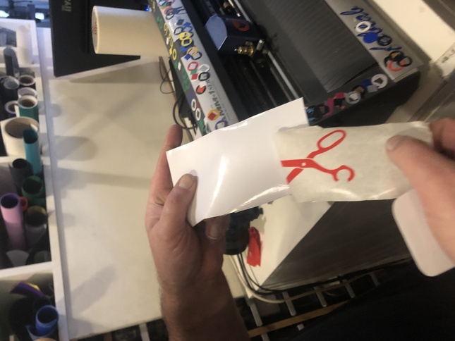
Ooohhhhhhhh, beaaautifulll!!!
Heatpress material
If you use heatpress material with your vinyl cutter you have to mirror your model.
Mods
To work with the vynil cutter we use the MODS software that you can open in your browser.
Mods wont read vector based images so we have to export the file as a SVG, PNG or a HPGL.
Design
One of the assignments is to make a sticker for your laptop.
I’m new to fusion so I want to use this software to generate the model for the sticker.
The plan in to make a text or shape that fits with my apple logo. This makes the measurements of my logo are imported.
I measured my apple logo and imported it into fusion. I used this tutorial to find out how to import and scale and dimension the logo.
I traced the logo (check if fusion has a trace path feature next time) and created an ouline of my apple logo and redisigned the logo.
Group assignment:
Characterise your lasercutter’s focus
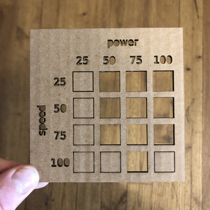
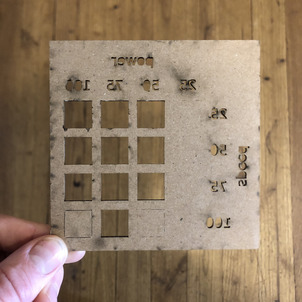
Characterise power, speed
To characterise the laser cutters power and speed we made 3 chards. That visualise the combined power and speed. The min power we pinned at 10 and is disregarded in this research. We used 3 types of material. All of them are 3 mm thick.
Carton
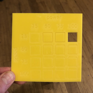
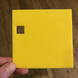
Acrylic
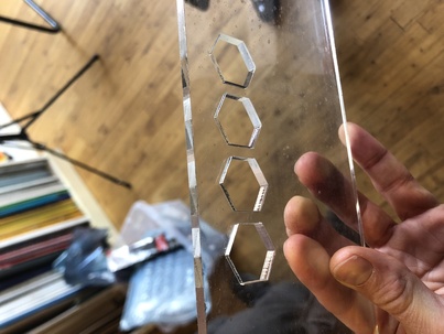
Characterise kerf offset
When talking about CNC shape cutting with typical cutting processes, a kerf is the width of material that the process removes as it cuts through the plate.

There are different CNC shape cutting techniques. Each cutting technique has a differtent kerf offset. To get an idea see offsets below;
- Plasma: 0.150”
- Oxy-Fuel: 0.045”
- Waterjet: 0.035”
- Laser: 0.025”
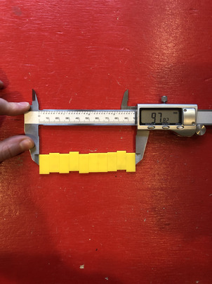
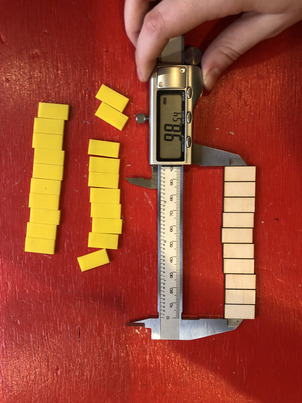
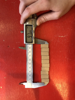
To characterise de kerf offset of our lasermachine Michelle cut 10 pieces of the same seize over a total distance of 100 mm. In theory all of the 10 pieces should have a width of 10 mm. But the laser removes material and creates residues in smoke or/and in mass. This creates the so called kerf offset.
To calculate the kerf offset we made the following calculation:
Acrylic 3mm
100 - 97,82 = 2,18 / 10 = 0,218 kerf offset
Multiplex 3mm
100 - 98,54 = 1,46 / 10 = 0,146 Kerf offset
Carton 3 mm
100 - 97,89 = 2,11 / 10 = 0,211 Kerf offset
Characterise joint clearance and types
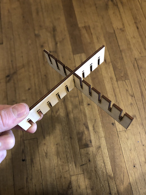
To see which measurements work for the joints Michelle made a comb with different dimensions. We tried the differrent openings to see which dimensions work best.
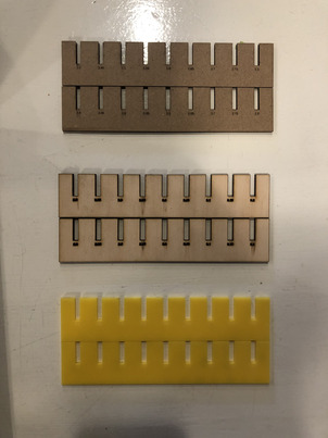
Acrylic
Only one option worked for the acrylic. The 2.8 with the 2.8 worked the best. We might give 2.7 and maybe less a chance to see and feel what happens when its to thight. Maybe the material will break or bend, etc.
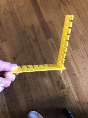
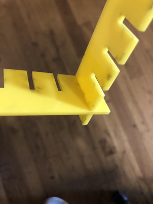
Carton
With carton a lot of widths worked. Everything below 2.7 mm was working fine. This is the result of de flexibility of the material. 2.6 perfect?
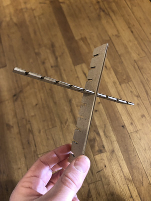

Multiplex
The 2,95 worked best without a doubt.
Fusion 360 parametric design
What’s parametric design?
Parametric design is a design method where features (such as building elements and engineering components) are shaped according to algorithmic processes, in contrast to being designed directly. In this method, parameters and rules determine the relationship between design intent and design response.
Plan
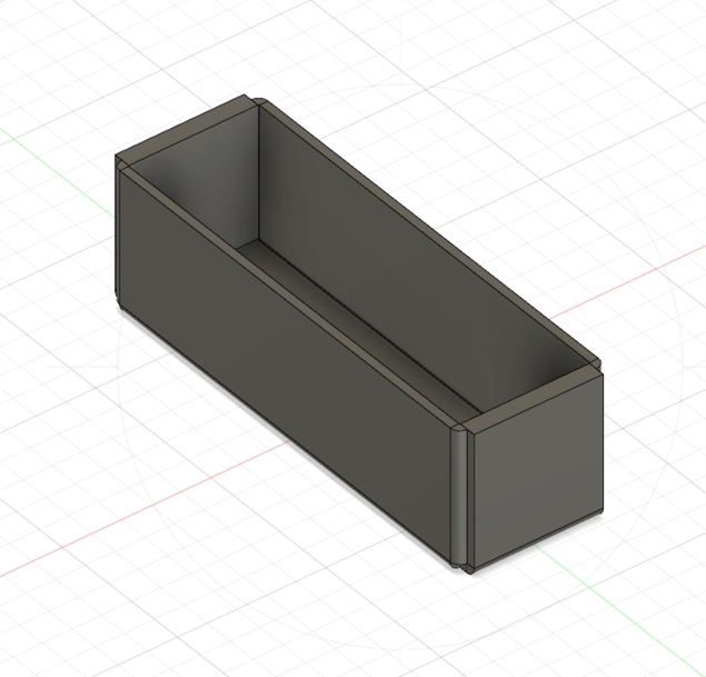
My plan is not very exciting but the idea came up to make a srew storage cupboard design that I can easily expand. I have a little atelier and I tend to keep a lot of things. Storage cupboards are pretty expensive so I’ll give it a shot to make one myself. Also I want to get familiar with the sheet metal feature.
First I’ll start with a simple box and after I’ll try to make a parametric screw container box.
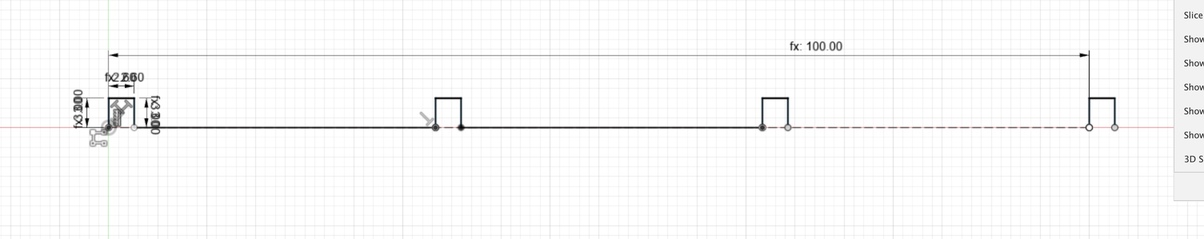
Parametric carton box
How to parametric design in fusion
1: fully define your sketch 2: modify - change parameters 3: set parameters 4: dotted/dashed line in fusion for bending. CAN’T YOU DO THIS IN FUSION???? made a construction line instead
I made a parametric carton box. I hope there’s a function for dashed lines in Fusion 360. It’s a super simple model but I get the idea of parametric design now and it’s super handy. Let’s try out the sheet metal feature now so we can see the model in 3d.
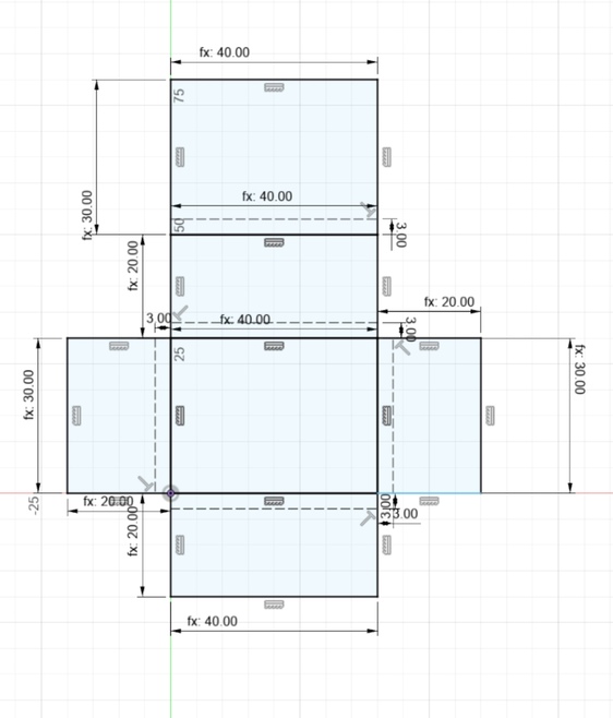
In the parameters you can add the dimension of your product and you’ll get a precise box out of it.
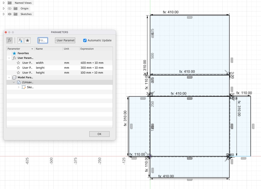
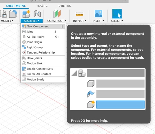
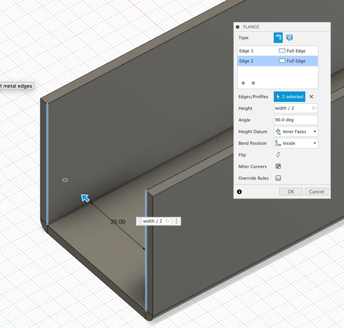
parametric tool storage cabinet with Sheet metal function
1: set parameters 2: new component 3: new assemble
4 : set new sheet metal rule (k factor = strecht. our corrugated material is not going to stretch)
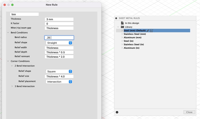
5: use flange tool - automatically uses the thickness 6: Use flange tool for edges. If you use the inside and outside tool don’t forget to add the material thickness for outside. 7: think of small parameters when you build your model -> width/2

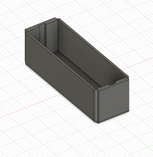
8: Made a little box. Now I want my parameters set in an assembly. So when my screw box is larger the amount of my drawers also multiply.
When I flatten my model. It’s not doing what I want it to do.
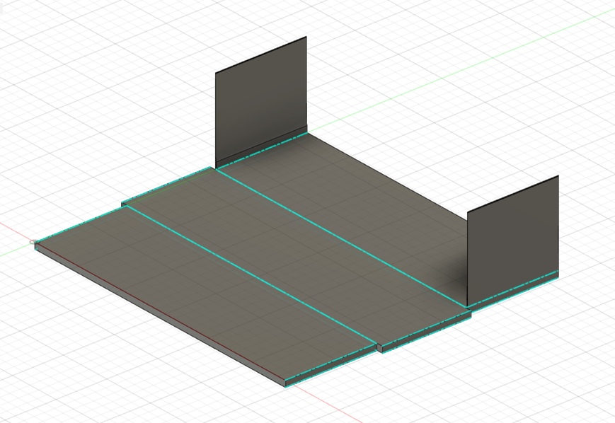
In the image below you see that I selected two edges for strenght purposes. In the above image te flatten part is not following my orders.
I changed my parameter and now it kind of does what I want

But the gap that you see is still not my intention.
Parametric assemby
What do I want?
I want a cupboard. When the dimensions of the cupboard change. The amount of drawers should also change.
Joints
Types of joints for cardboard
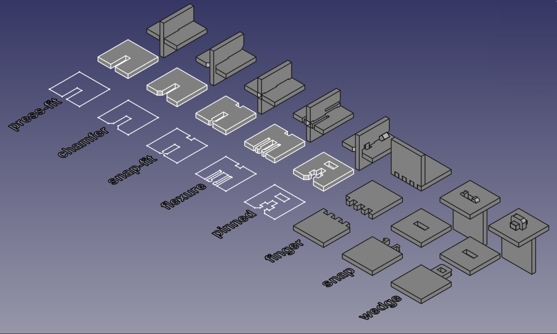
Lol. Found a fab design on Pinterest. fun link
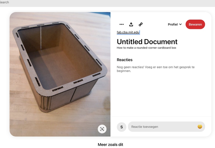
I you type in - storage box lasercut, you get 100000 options. So my idea is truly not special.
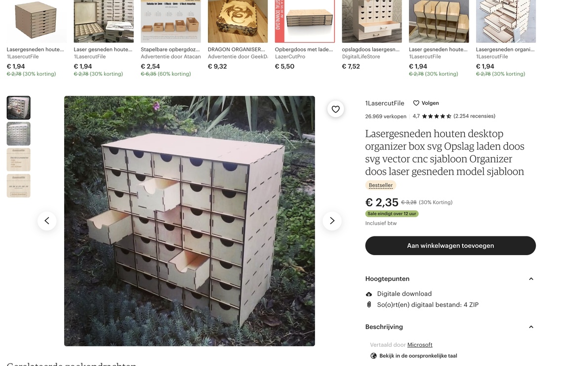
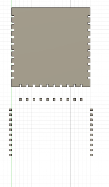
storage cupboard
When I try to make my joints paramatric it won’t work.
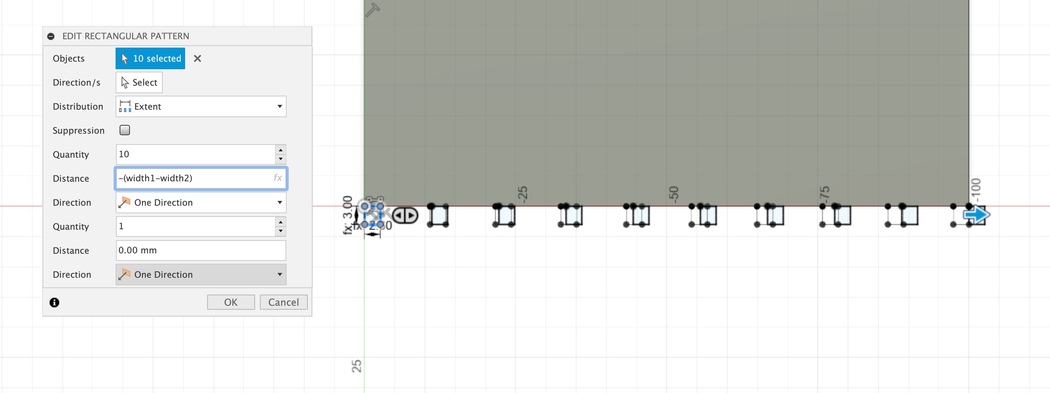
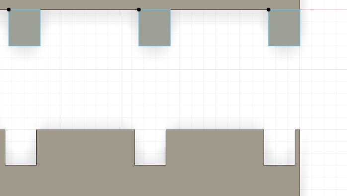
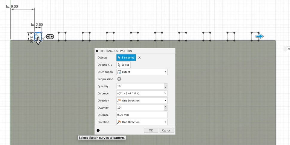
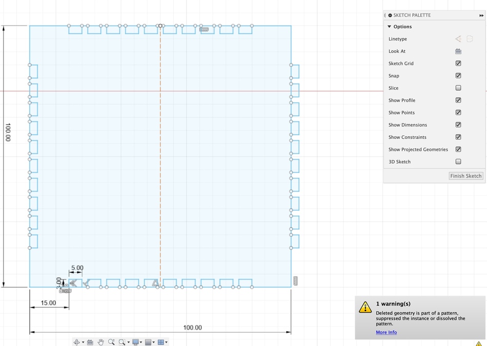
Now I try to do a pattern when it’s extruded. But When I want to pattern it I can’t select the joint, only the hole feature because it’s merged..

Now it should work! I used a little equation to set my pattern right. Use ‘’()’’ !
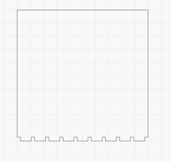
I think that when I want to export this as a DXF the joints will be cut loose. I should rebuild the sketch I think.

This is not possible of course. Because the sketch isn’t closed so I can’t extrude.

Using the same pattern dimensions for my cut. If I want to change the amounts of my joints I need to change the extrude amount of my cut and my extrude.

Oops, did something wrong here. Probably used length instead of width parameters
It works now. I’m not sure why one side of the joints stay blue. Help!
Here I need to pay attention at the dimensions that I fill in.

Oops, didn’t thought about this.
I think I can make this smarter. Let’s sketch it out.
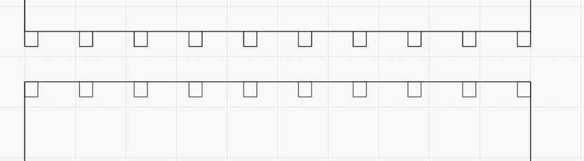
- Make every body out of one sketch
- Start with spacing end with spacing
- make a plan for the placing of the joints
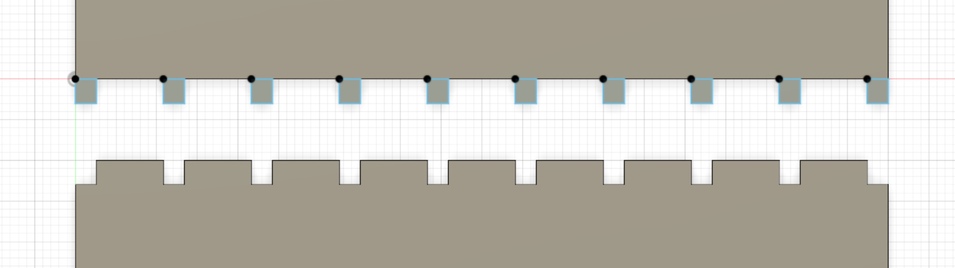
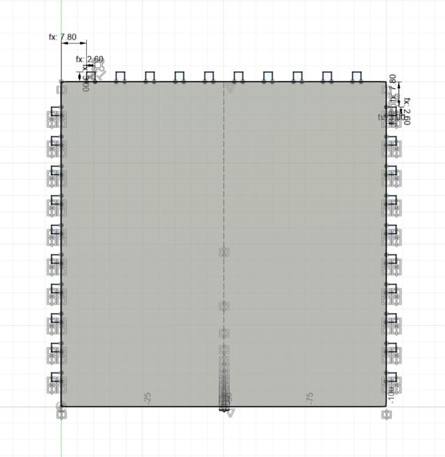
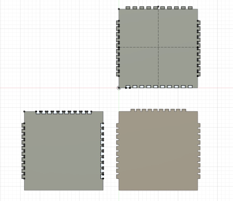
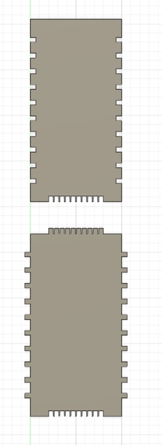
Now I set my parameter right! I didn’t started with a spacing. Now I did! And I have a better overview of my model cause I worked in les sketches and extruded all my sketches all at once.
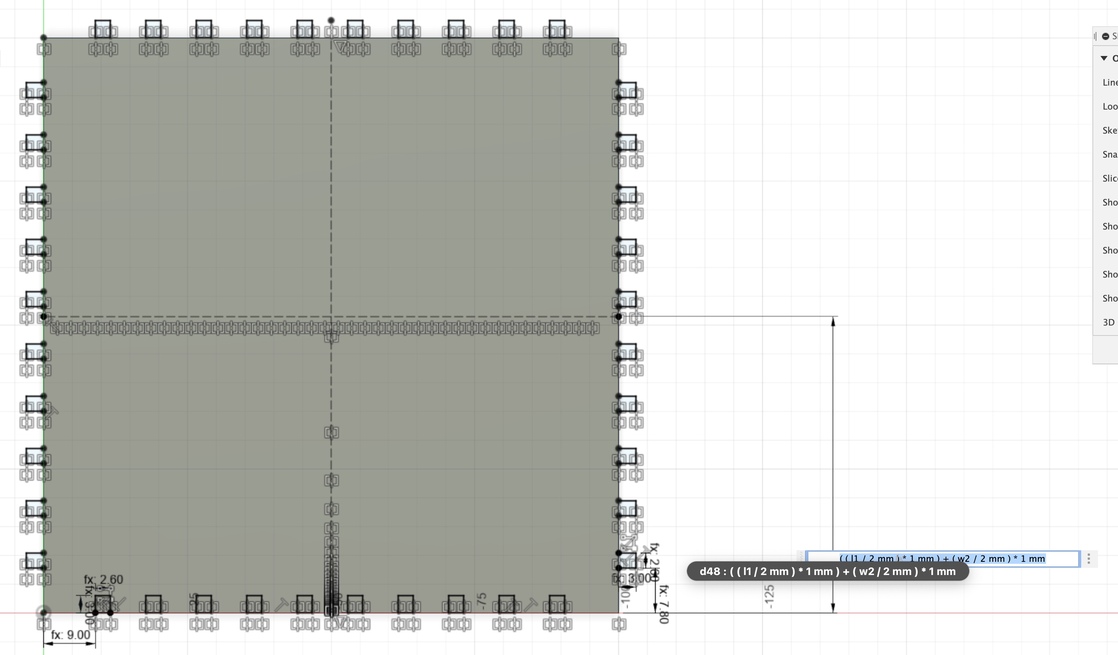
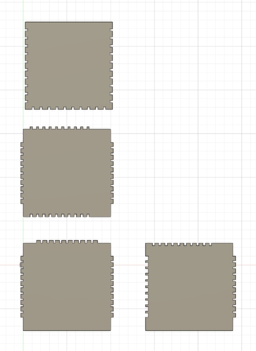
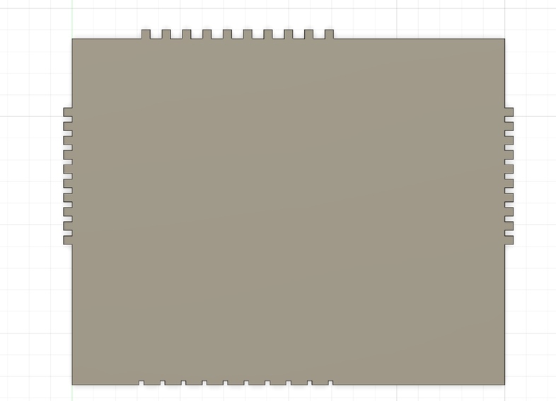
I made all my extrudes in one sketch. Used the pattern and mirror tool and everything is connected to my parameters. Let’s goooooo
For this equation I need the w2 devide by 2 because the mirror feature is centered based
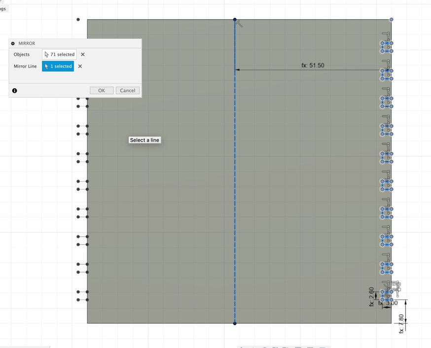
I shouldn’t use the mirror feature here but the pattern feature!!
I changed my parameters to check if it would work. Unfortunately not everything worked as it should. I’ll try to find out what it is.
I used a wrong parametric value. It’s fixed now.
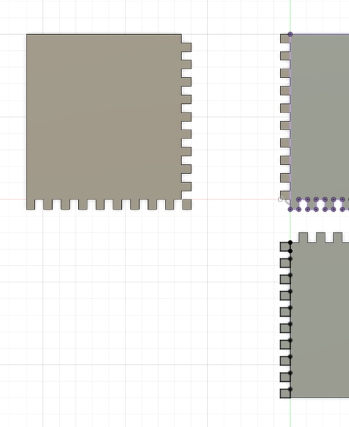
When I try to export this model it won’t work how I want it too. Why? Because I used the mirror feature instead of the pattern feature. No, that’s not true of course. I should mirror this.
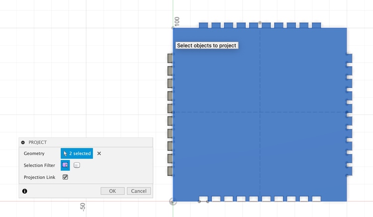
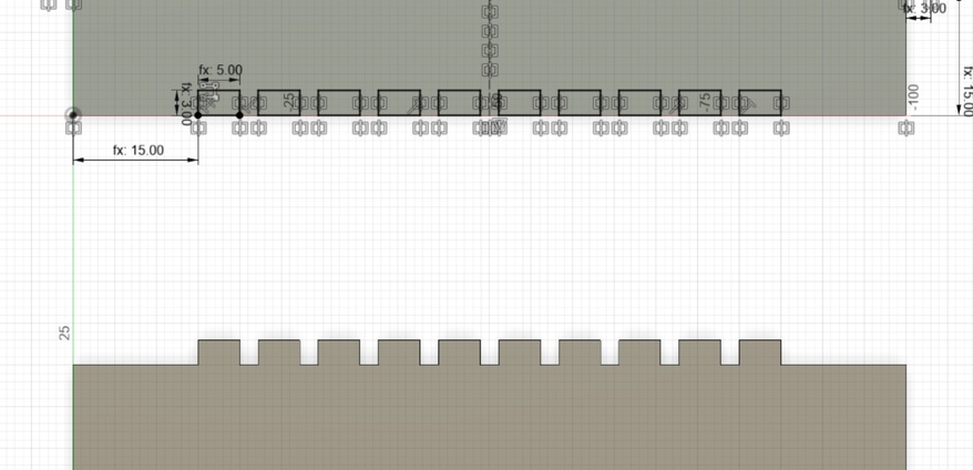
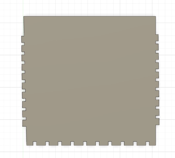
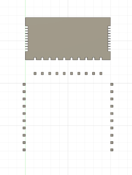
instead of extrude cut a extruded body I created a sketch with my wanted designs in it. See below.

The one on top I just made. It looks way more peaceful, hahah.

I deleted everything and I’ll start over again. I was getting to messy.
Instead of making every sketch from scratch I copied the sketch and edited it.
I’m super fast now!!!! luckily I made my model again!!! Oops be careful here. When I keep this my parameters won’t work probably. Lets check it out.
I turned them in construciton lines now. Wow, I’m pretty smart men.

I checked my parameters to see what’s up. Shit, I’m not smart after all…….
Shit I have to put some extra dimensions in my parametric table. I can only make squars now!
I’ll give my model som extra parameters so I have more control.

w1 - ( offset * 2 + ( l2 ) )
Copying was a good idea. But I didn’t constrain in properly. So when I try to edit it my total model curves.
Okay, this goes terribly wrong. I copied it and now all my constrains are fucked. I’ll start over AGAIN!
If I change my hight parameters. My model disappears…..
When I change my with it does work though….. hmmmmmmm Wha’s wrong?
It’s got something to do with my latest model… Not sure what I’m doing wrong.
Laser cutting my model
Export for lasercutter
Let’s try to export this as a file that I can use in de laser cutter. Just to be sure. Maybe I can’t after I modelled everything….. you never know.
oops….

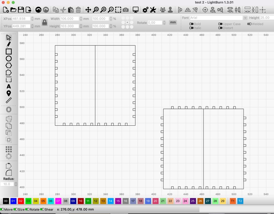
Lets try out with lghtburn. First need to download it though.
Opend my model in lightburn but my lines are not imported how I want them.
Eeeeeeeeeasy. No need to stress. Watch this tutorial. No need to watch everything 00:00 - 01:40 is enough.
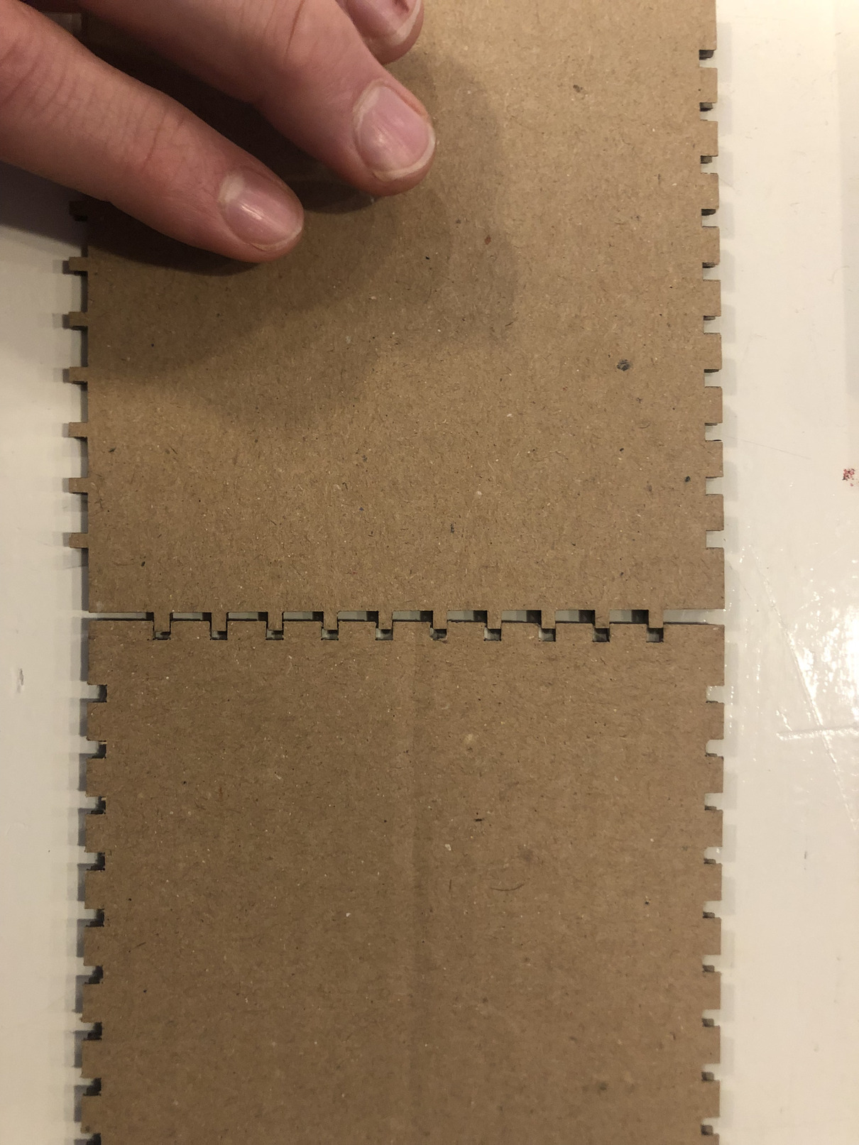
Let’s try to make a laser cut whit the models that I have now. Because this takes ages….
I used power 25 and speed 25. I think I should use less speed.

Hahahhaha, this is an absolute joke. Think of your kerf mister. The kerf of my model is 0,211
Final Model (I hope)
width: width - ( offset * 2 + male ) lenght: -lenght + ( offset * 2 + male )
If I take the kerf distance in account the male and female are not in the correct opposite direction….
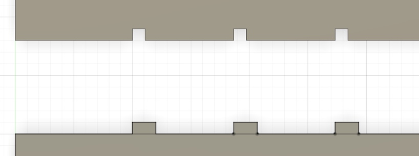
I should create another offset parameter for the female and the male gap. Let’s try the following equations:
offset - (male/2)
offset - (female/2)
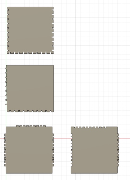
YASSSS! This seems to work.

But now I need to change my parameters in my patterns too.
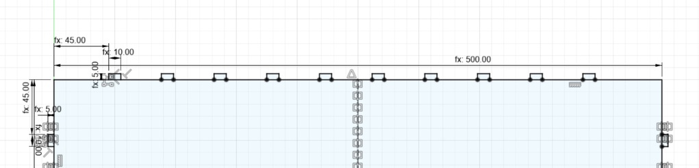
I use the following equations for my patterns:
width (male): -lenght + ( (offset-(male/2)) * 2 + male )
length (male): -lenght + ( ( offset - ( male / 2 ) ) * 2 + male )
width (female): width - ( ( offset - ( female / 2 ) ) * 2 + female )
lenght (female): length - ( ( offset - ( female / 2 ) ) * 2 + female )
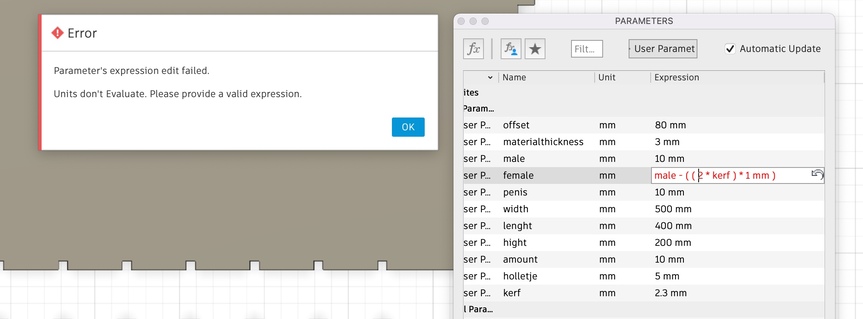
I wanted to add a kerf in my parameters. But I got an error. Is this too meta for fusion? It’s not that bad though because I can edit it easily.
Parameters in pattern feature
Can’t I use a parameter in the quantity in a pattern feature?
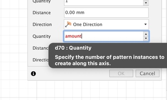
When I do this the following is happening.
When I delete the extrude the parameters do work. I’ll try if it will work if extrude it after the change.

Yes, it seems to work now! Huh…… check ->
Maybe is should extrude both of them again when for both paths the parameter ‘’pattern’’ is changed.
My mirror option is not smart enough to do this

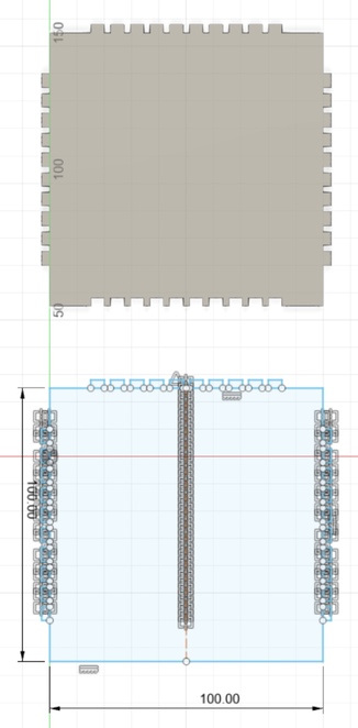
It works now. Hopefully when I extrude both bodies, it will work too. ->> Yessssss, It works. I think I’ll extrude my sketches in the end. I think it will make mr Fusion live a bit easier (and mine as well)
Conclusion
I did and learned a lot this week! Fusion 360 cost me so much time that I didn’t really made a nice end piece. I’m still working on a parametric box for my electronic components for my studio. But I’ll finish the design and try to make it when I have more time left.
Notes
Final model
1: Draw a square, I used 20mm x 20mm.
2: Draw X and Y axes on your cutted square. Some lasers vary in kerf due to the cutting direction.
3: measure the the width and lenght wirth a caliper.
4: 20mm - measured with = kerf almost ready . To know the kerf you need to devide it by 2 of course.
Created a tool path for the Laser Cutter in De Waag with the help of this link
- manufacture tab
- manage
- tool library
- click
plus buttongo to laser cutter. Give name - select the kerf under geometry
- Click Ok now and copy the tool in to the local library. We need this otherwise we can’t export it.
You can follow these steps to export the file without manually change the kerf in your parametric deign. But just adjust it in the toolpath that you had selected above.
- when you have
- manufacture workspace
- setup - new setup
- cutting
- select the pieces of your model
- cutting action - 2s profile
- select the tool that you just made
- select geometry
- select passes - left or right (no center!)
-
conpensation type - in computer
-
post process
- select your source