6. Electronics Design
Intro
This week we’ll focus on electronic design. This is a theme that’s pretty complicated because there are a lot of components out there that I kind of know, but not yet understand. For me this week is all about knowing what’s out there and how it works.
Group assignment:
Use the test equipment in your lab to observe the operation of a microcontroller circuit board (as a minimum, you should demonstrate the use of a multimeter and oscilloscope) Document your work on the group work page and reflect what you learned on your individual page
Individual assignment:
Design a development board to interact and communicate with an embedded microcontroller
A microcontroller is like a miniaturized computer on a single chip. All the elements of a computer, such as CPU, memory, timers, and registers, are tightly integrated with each other. A microprocessor, on the other hand, is just the computing element (the CPU) in a computer.
Development Boards are printed circuit boards with a microcontroller/microprocessor mounted on them with few other hardware components. Development boards are meant for System Designers to become acquainted with programming a processor onboard and also to develop and test projects effectively and efficiently.
Presentation
Erwin, a former student of fablab shared his knowlegde about his hobby: electronics. He had a lot of interesting things to say.
Circuit: is a closed loop where elctronics can flow. In this circuit there are 3 factors that are most important.
| What | measured | written | explanation |
|---|---|---|---|
| The voltage | measured is volts | written as V | It is the difference in electric potential between two points. Batteries are common sources of voltage in many electrical circuits. |
| The current | measured in amperes | written as I | This is the stream of electrons moving through the circuit. |
| The power | measured in watts | written as P | This gives the electrical energy that is transferred through the circuit (per unit of time, with watt being the amount of joule per second). |
- Circuit: is a closed loop where elctronics can flow
- Voltage (spanning): V. Sum of all voltages around a loop = 0
- Ampere (stroom): I, Ampere. Sum of all currents in a node = 0
- Power: p, Watt P = V*I
- Energy = Power * time (e.g. kWh)
- resistor = Resistor (R, Ω, Ohm) R = V/I
- Capacitor = C, farad. A storage tank for electric fields (charge).
- Hoeveelheid lading op capacitor = Q
- frequentie = hertz (HZ) = cycles/seconds
Formulas
R = V/I
P = V*I
C = Q/V and I = C dV/dt
Microcontroller
Integrated Circuit, built from transistors
Programmable device with inputs, outputs, memory and
calculation engine (ALU)
–Digital inputs and outputs (I/O)
–Analog inputs (ADC)
–Analog outputs (DAC)
–Digital interfaces (serial, i2c, spi, twi, updi, jtag, …)
Controlled by registers
Microprocessor is just memory and ALU
ALU: An arithmetic logic unit (ALU) is a digital circuit used to perform arithmetic and logic operations. It represents the fundamental building block of the central processing unit (CPU) of a computer. Modern CPUs contain very powerful and complex ALUs.
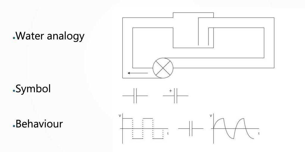
Water analogy

The water/hose analogy for electricity is useful for explaining voltage, current, and power. In general terms, charge is water, voltage is the pressure of water, current is the flow of the water. Power is the total amount of water flowing in given time.
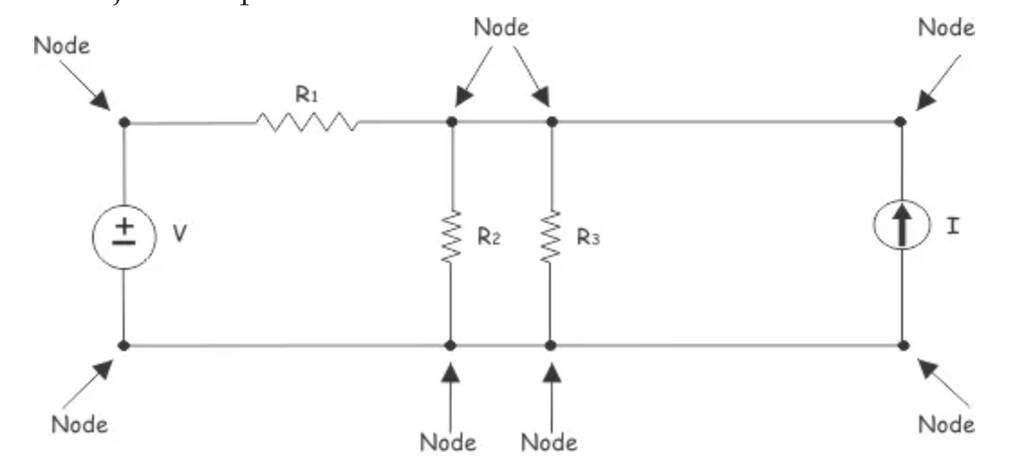
node
The point through which an circuit element is connected to the circuit is called node. It is better to say, node is a point where, terminal of two or more circuit elements are connected together. Node is a junction point in the circuit.
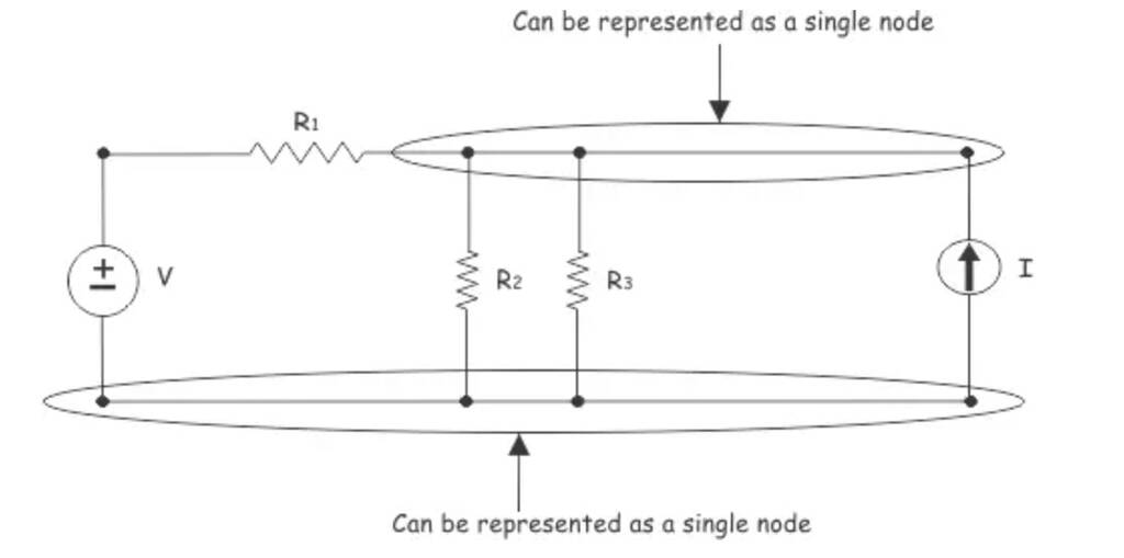
If three is no element between two or more connected adjacent nodes, these nodes can be recombined as a single node.
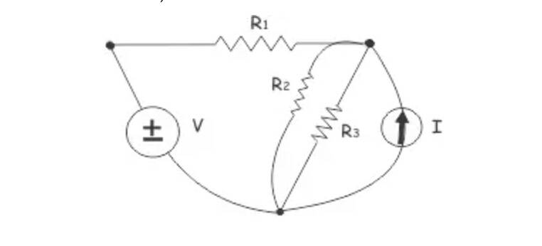
Finally, the circuit can be redrawn as,
branch
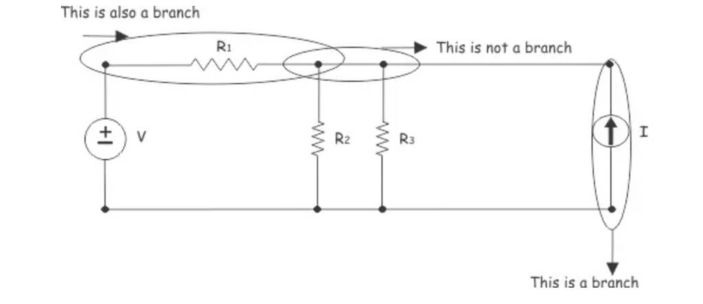
Loop: is any closed path in the circuit formed by branches.

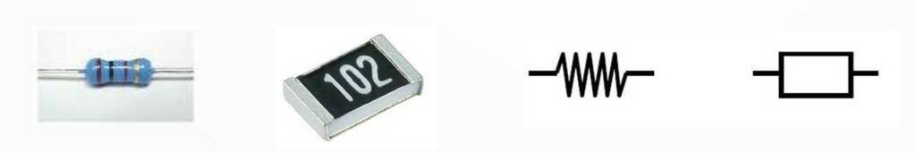
Resistor
A resistance for electrons
No polarity
A current-limiter
One of the most important components

Capacitor
A storage tank for electric fields (charge)
C = Q/V and I = C dV/dt
Often used in filters
“DC opening, AC resistor”
Can be unpolarized (ceramic, tantalum)
Can be polarized (electrolytic)
Diode
diodes explained
working principle diode
A diode is a semiconductor device that essentially acts as a one-way switch for current. It allows current to flow easily in one direction, but severely restricts current from flowing in the opposite direction. An ideal diode will have zero resistance in one direction, and infinite resistance in the reverse direction.
Although in the real world, diodes can not achieve zero or infinite resistance. Instead, a diode will have negligible resistance in one direction (to allow current flow), and very high resistance in the reverse direction (to prevent current flow). A diode is effectively like a valve for an electrical circuit.

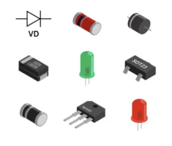
One-way valve for electrons
Often used as bridge rectifier bridge rectifier
Light Emitting Diode (LED)
Color depends on elements used
Also light sensitive
Forward voltage, Forward current
LED example: VF = 2V1, I = 10mA, Source = 5V Calculate R and select common R Hint: R = V / I
Diode bridge
A diode bridge is a bridge rectifier circuit of four diodes that is used in the process of converting alternating current (AC) from the input terminals to direct current (DC, i.e. fixed polarity) on the output terminals. Its function is to convert the negative-going AC pulses into positive going pulses, after which a low-pass filter can be used to smooth the result into DC.

flyback diode
A flyback diode isn’t a specially made diode, it’s a regular diode placed next to an inductive device like a relay or door holder so the diode will protect the rest of the electrical circuit from the inductive device.
A flyback diode is any diode connected across an inductor used to eliminate flyback, which is the sudden voltage spike seen across an inductive load when its supply current is suddenly reduced or interrupted. It is used in circuits in which inductive loads are controlled by switches, and in switching power supplies and inverters.
This diode is known by many other names, such as snubber diode, commutating diode, freewheeling diode, suppressor diode, clamp diode, or catch diode.
Coil (L,Henry)
An inductor, also called a coil, choke, or reactor, is a passive two-terminal electrical component that stores energy in a magnetic field when electric current flows through it.[1] An inductor typically consists of an insulated wire wound into a coil.
Othernames: inducter, choke, reactor
A storage tank for magnetic fields
L = V / dI/dt
Used in relais and motors
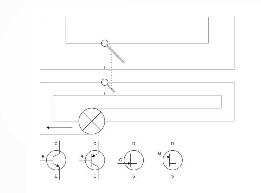
Transistor (Q)
A transistor is a miniature semiconductor that regulates or controls current or voltage flow in addition amplifying and generating these electrical signals and acting as a switch/gate for them. Typically, transistors consist of three layers, or terminals, of a semiconductor material, each of which can carry a current.
Amplifier and/or switch
A small current can amplify a larger current
Ic = β * Ib where β = amplification factor
A small voltage can drive a larger current
Hertz
How to Calculate Frequency in Hertz RELATED How to Calculate Frequency in Hertz Updated November 06, 2018 By Chris Deziel You hear the term hertz in electricity as well as when discussing the transmission of electromagnetic waves – of which light and radio waves are examples – and the speed of computer processors. The common factor in all these phenomena is that they involve some type oscillation, and the hertz unit is used for measuring of the frequency of these oscillations. It has a simple meaning. One hertz is simply one cycle per second. It’s usually written in its abbreviated form, which is Hz. Thus, instead of writing 100 cycles per second, scientists write 100 Hz.
Measuring
For the group assignment we used an Arduino Uno board to observe the operations.
Multimeter
If you want to become a true multimaker guru. You should read this link. The most basic things we measure are voltage and current. A multimeter is also great for some basic sanity checks and troubleshooting. Is your circuit not working? Does the switch work? Put a meter on it! The multimeter is your first defense when troubleshooting a system. In this tutorial we will cover measuring voltage, current, resistance and continuity.
There are no really bad multimeters. I’ll try to buy them from the action.
Oscilloscope
Most versatile measurement tool - Multiple voltage in time domain - Frequency counter
Hardware-based PC based (w DAC)
Logic Analyzer
A logic analyzer measures and analyzes signals differently than an oscilloscope. The logic analyzer doesn’t measure analog details. Instead, it detects logic threshold levels. When you connect a logic analyzer to a digital circuit, you’re only concerned with the logic state of the signal.
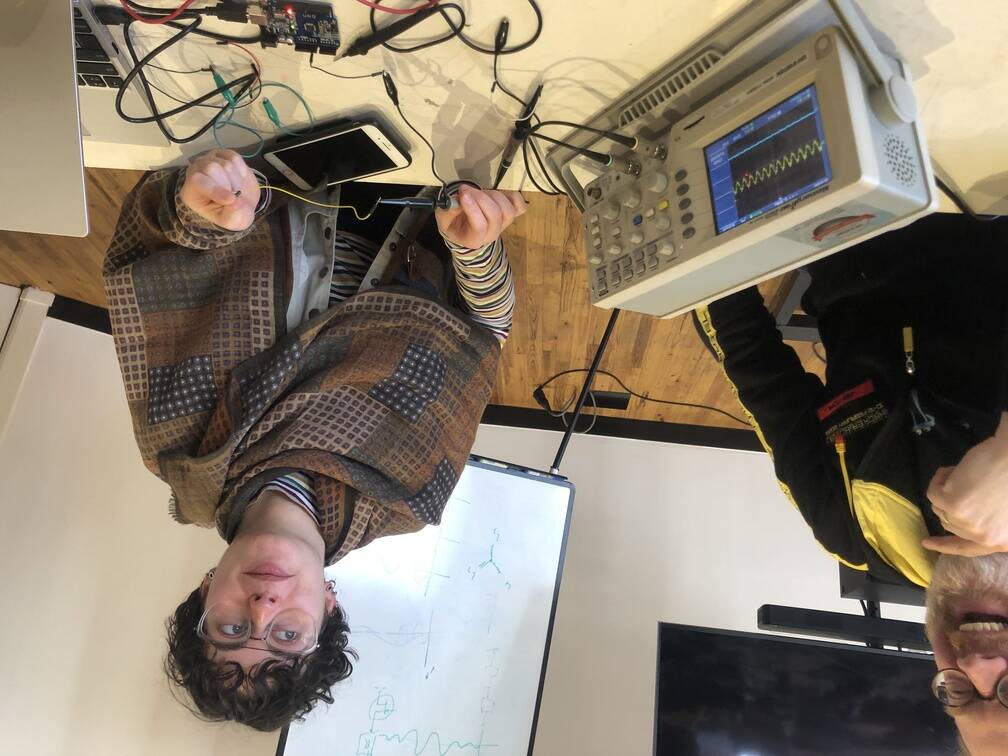
Group assignment
Erwin prorgammed the Uno. He gave as tip that it had someting to do with the de digital pins.
1: We saw that the led was blinking of the Uno.
2: With the multimeter we checked which pins where under load.
3: The digital pins where under load. Some of them were giving a weird signal. This makes sense of course beacause the were switching between high or low with. A stable outcome was not visible.
4: To find out what was happening we used the oscilloscope.
5: There was a little tension in de group so we attached the wires to Michelle to see what was going on. The graph went like crazy! What was happening? Michelle was an antenna and picked signals from the net.
6: Then we attached two different digital pins to the osciloscope to compare the signals.
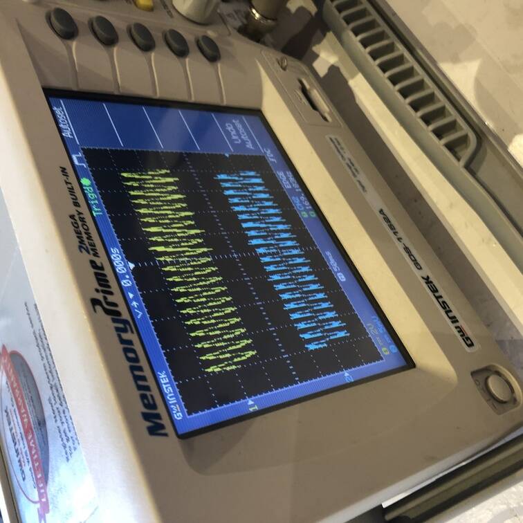
After adjusing the template correctly and setting the device on automatic. You could see that the signal was 24,938 HZ.
Softwares
Set up
For this assignment I used Nadieh’s fab lab page an a tutorial series.
individual project: design a development board to interact and communicate with an embedded microcontroller extra credit: try another design workflow extra credit: make a case for it extra credit: simulate its operation
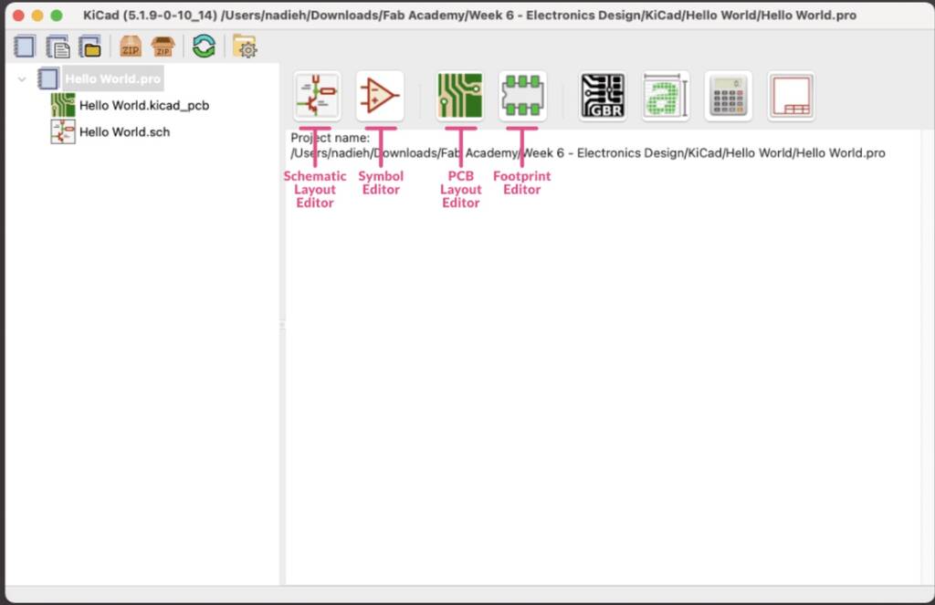
To design a development board I’ll use Kicad. KiCad is a free open source program to design schematics and design a PCB.
Kicad had different option available that will help you designing your circuit board.
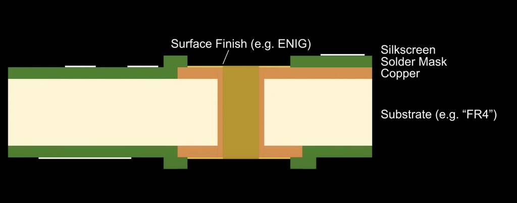
PCB: printed circuit board
WHich components do I want to use in my PCB?
- xiao esp32
- led
- push button
- Servo motors
- Joysticks
- Bluetooth
- resistors
First I downloaded KiCad and added the default settings. Then I followed the proces that was discribed at the library page on Github. This library (should) cover all the electronics components found in the official fab inventory. Using this library should also make it easier to share KiCad project files between Mac, Windows and Linux systems.
1: Clone or download this repository. You may rename the directory to fab.
2: Store it in a safe place such as ~/kicad/libraries or C:/kicad/libraries.
3: Run KiCad or open a KiCad .pro file.
4: Go to “Preferences / Manage Symbol Libraries” and add fab.kicad_sym as symbol library.
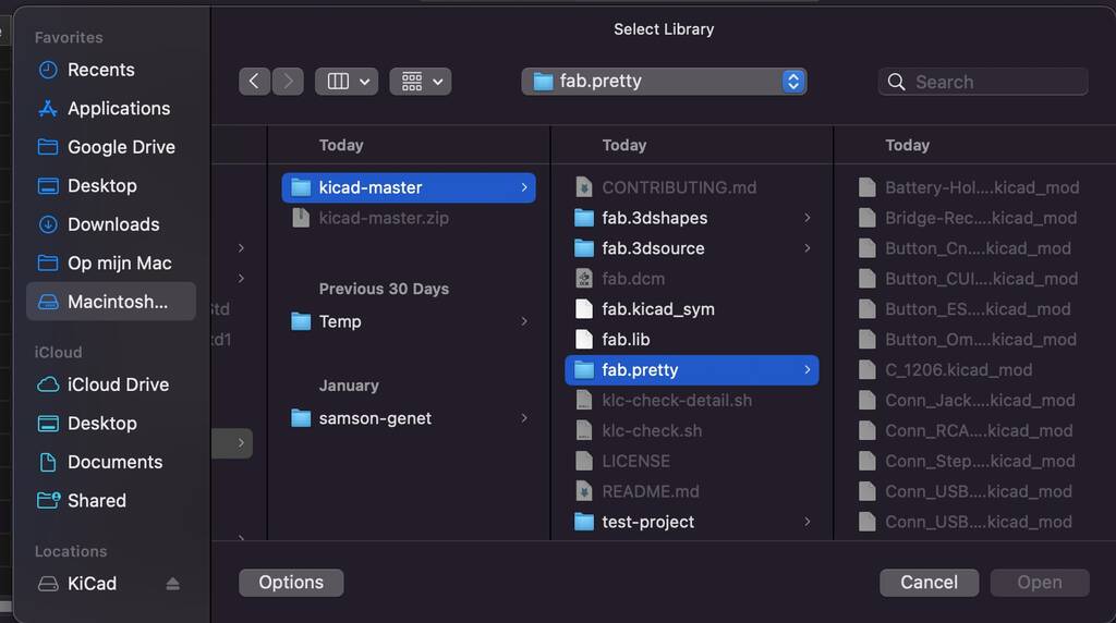
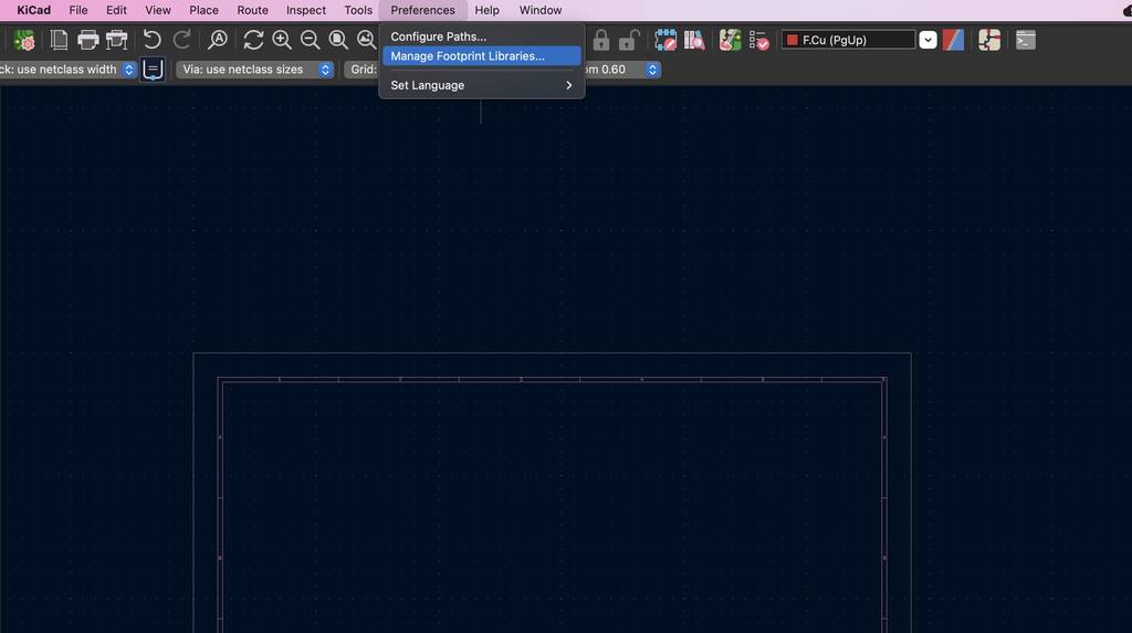
5: Go to “Preferences / Manage Footprint Libraries” and add fab.pretty as footprint library.
6: Go to “Preferences / Configure Paths” and add variable named FAB that points to the installation directory of the fab library, such as ~/kicad/libraries/fab or C:/kicad/libraries/fab. This will enable the custom 3D shapes to be found. The 3D shapes project has just started and most of them have to be populated still.
When I try to add the second folder I get this error.
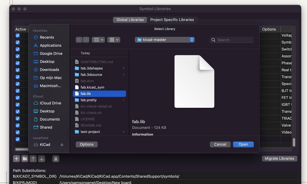
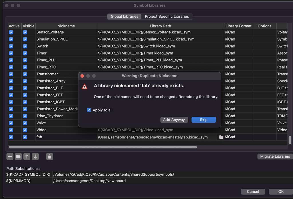
I can’t add the fab.pretty folder… I’ll take a look at this later on. Ah, I know why. Is should do this in the manage footprint library. READ! my friend.
Okay! Let’s start!
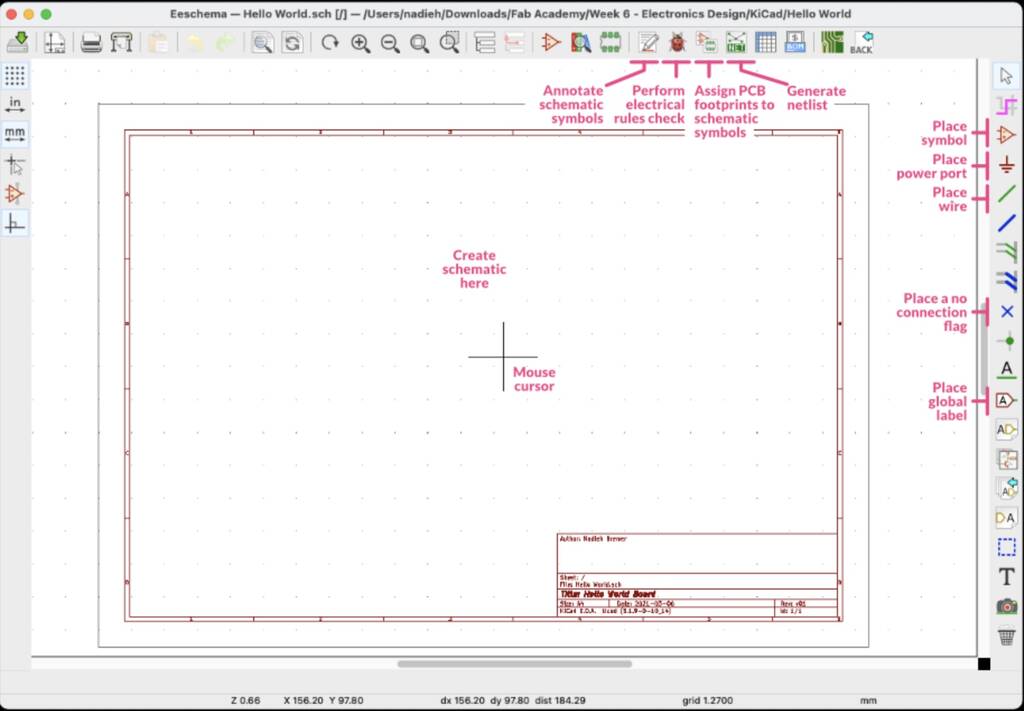
Schematic layout manager
In the schematic layout manager you can design your board. Here you can select the components you need and connect them to create a circuit.
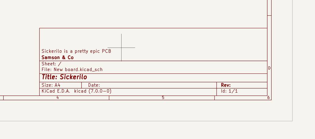
I’ve edited some text in my document. As you see I have high expectations of this PCB.
Adding components
Hot keys
Schematic editor
m: move
r: rotate
a: place antother component
c: copy
v: value editing (press while hovering over the component)
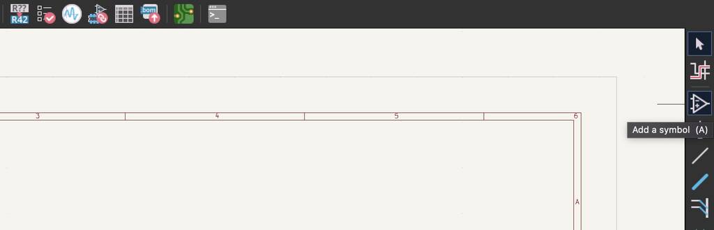
To add components go to the ‘add symbol’ icon. This will open up a new Choose Symbol window from which you can select your part, such as a resistor.
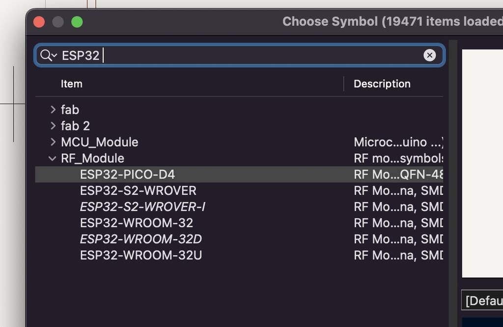
I’ll start with the most important part (I think) and that’s my beloved MCU, the ESP32-C3 by XIAO. First I thought it would’t appear but you need to write the full name.

I’m not sure what I need for the following features. Most of the features I can already control with the ESP wihtout adding more comopnents. To make this assignment more valuable I’ll add more components. OOPS, it doesn’t work like that the XIAO board uses the esp32 chip. So we will make a board of our own.
This tutorial explains and shows extra components that might come in handy in making a PCB with an ESP32. He also uses an CP2104. But we don’t need this since we can program our esp without it.
BOM
- xiao esp32
- led
- push button
- Servo motors
- Joysticks
- Bluetooth
- resistors
BOM
- led
- push button (tactile)
- VCC
- GND
- Reset (do I need this? My esp32 allready has one)
- Decoupling capacitors
- V_bat_measure
- Batteries 3.3V
- battery holder
- joysticks (potentiometer based) (analog pins)
- on/off button
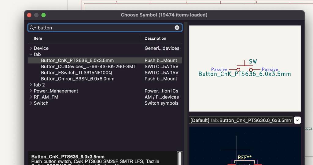
I have know idea what the difference is between these buttons. That’s also the case for the variaty of LEDS that are available.
Controller
This is a nice tutorial to design your own controller.
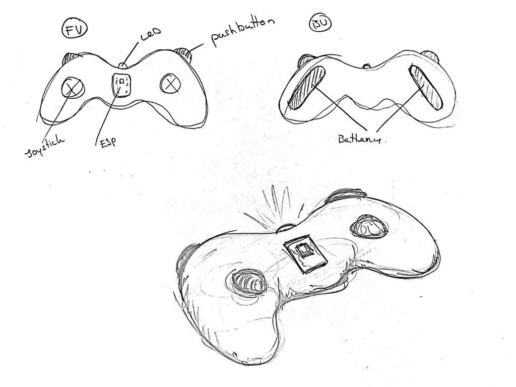
It’s a little vague what I want so I think it’s time to visualise so I’ll get things more specific.
I’ll make a controller so I can control my tentacle over bluetooth.

All of the components where easy to found. But a joystick is a little different to import, since the component is not imported as is. Before we can import the component we need to understand how it works.
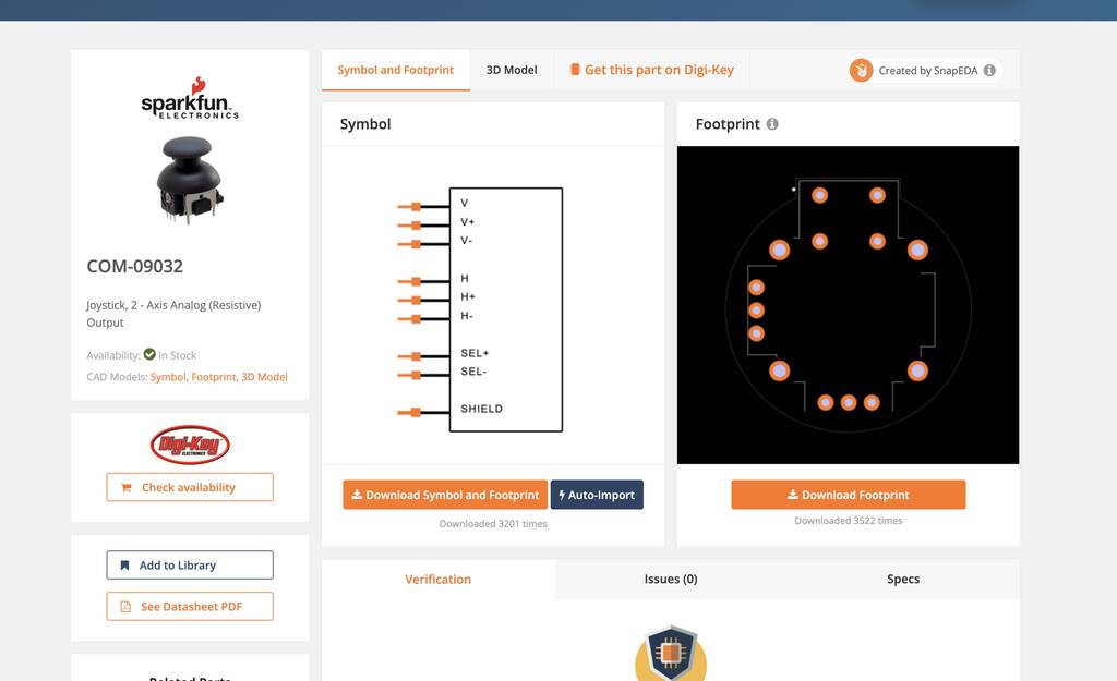
The joystick has a push button and works with 2 potentiometers. one for the X-axes and the other one for the Y-axes. Also we need to know the dimensions of the joystick that we’ll use. In the ‘embedded programming’ week we searched for datasheet. Here I chose for this joystick
Operating Voltage: 5V
Internal Potentiometer value: 10k
2.54mm pin interface leads
Dimensions: 1.57 in x 1.02 in x 1.26 in (4.0 cm x 2.6 cm x 3.2 cm)
Operating temperature: 0 to 70 °C
All the information is quite clear for this component. But after a little research I found a way to download the footprint of a joystick. Unforntunately I couln’t find it from this specific joystick. But it’s pretty much all the same. So from now on we’ll work with this joystick
Besides all the needed information this component also has the option to download an EDA model.
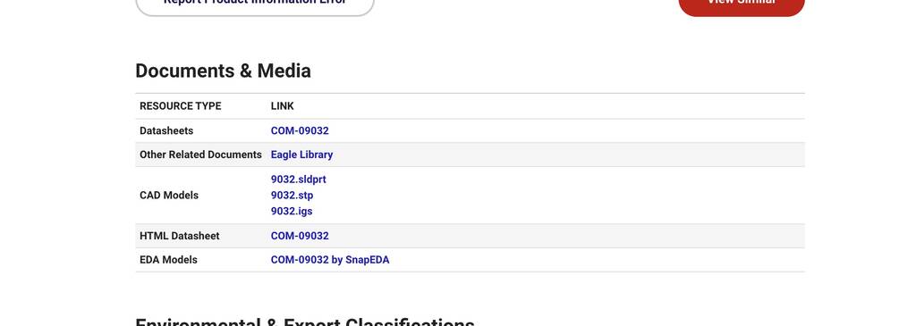
Go to Snapeda. You need to create an account to download the components. But it’s free and I read good things about it.
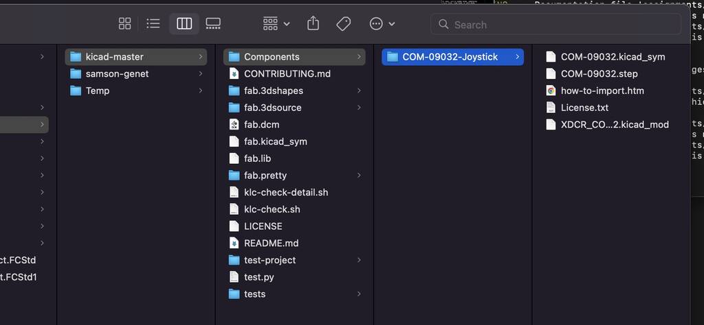
I downloaded the Symbol and footprint and created a component folder in my KiCad directory.
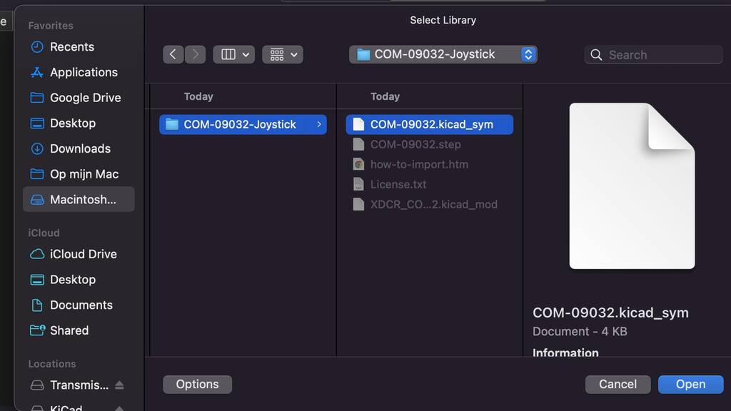
To add this library I’ll go to preferences -> manage symbol libraries -> project specific libraries.
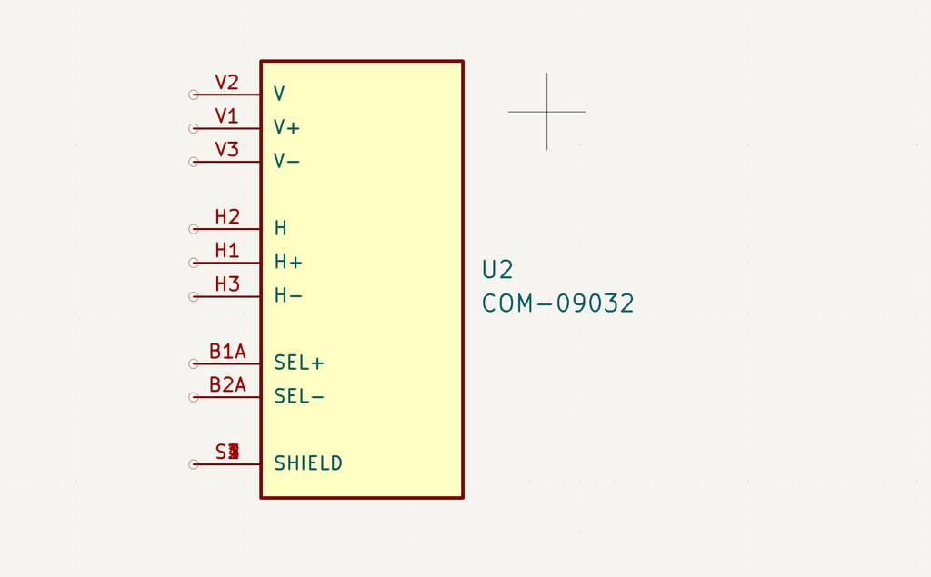
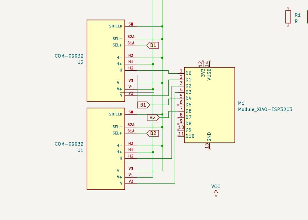
The Joystick COM-0932 has the following schematich display. There’re a lot of pins so I’ll in order to understand I need to know what’s up.
v = Vertical axes
v1 = voltage high
v3 = voltage low
v2 = Voltage drop
h = Horizantal axes
‘’
‘’
‘’
‘’
B1A = high (I think) B1A = low (I think)
Shield = extra pins to solder to.
Wiring components
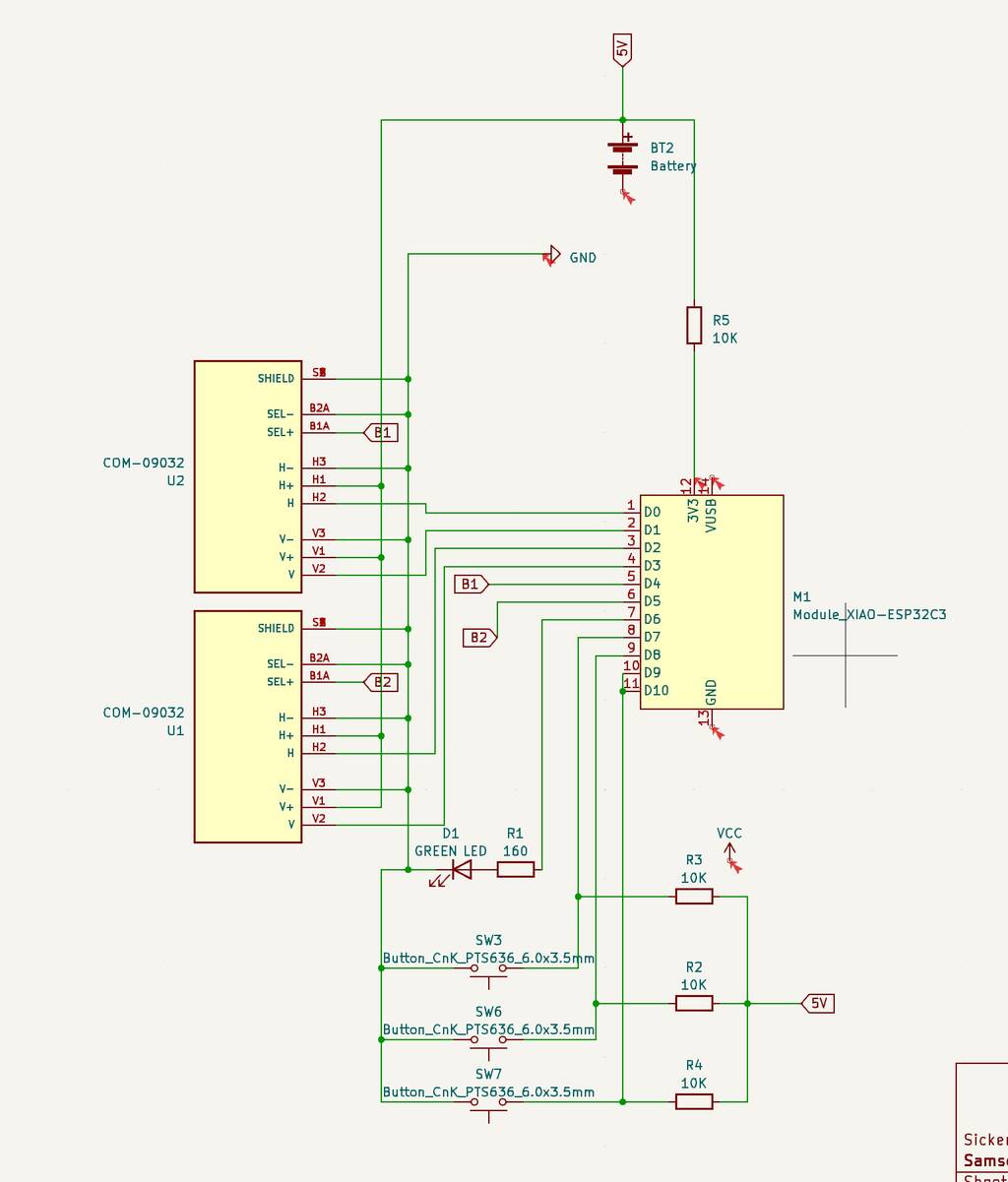
In order to wire the components we need to know where to wire them to. For this we need the pin layout from the esp32-c3 XIAO.
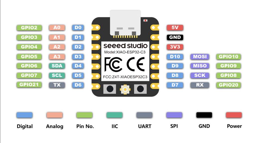
D0 - D3 are analog pins. These pins we need for the joysticks.
I drew lines to the fitting pins. I need to order my drawing better. This isn’t handy. If I select all the things that I want to move they won’t stay attached. I think I’ll find a way later on how to move stuff and stay connected to the correct pins. I have faith in KiCad it hasn’t yet surprised me with weird things.
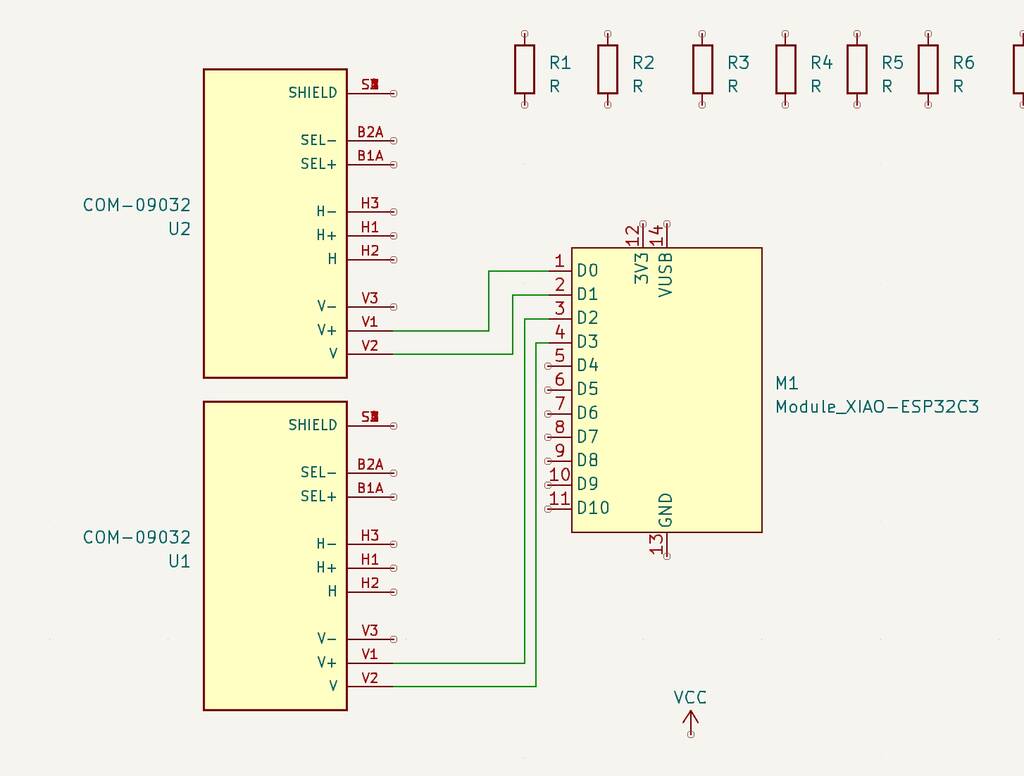
I try to find wether I can control my joysticks with 3.3 v. I can’t find it in the datasheet. But since my joystick works with analog pins I think the amount of voltage doesn’t matter. I think its wise to connect my joysticks to an external power supply instead through the MCU. The MCU Runs on 3.3 volts.
No, this is a bad plan. The previous joystick runs on 5V. I’ll go for an 5V external power supply. It’s also good for the assignment.
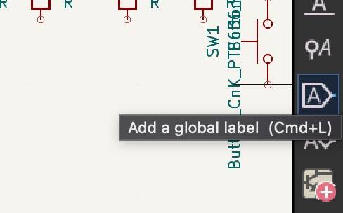
Add net label is a good tool to organise your schematic better.
Oops, this looks like a mess.
This looks a bit better. Next time I’ll design it smarter.
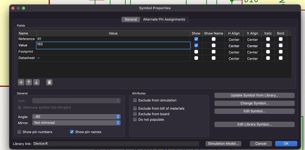
Giving value
By double clickting on the icon. You can set the value. For these LEDS I’ll go for a 160 ohm resistor.
R = V/I
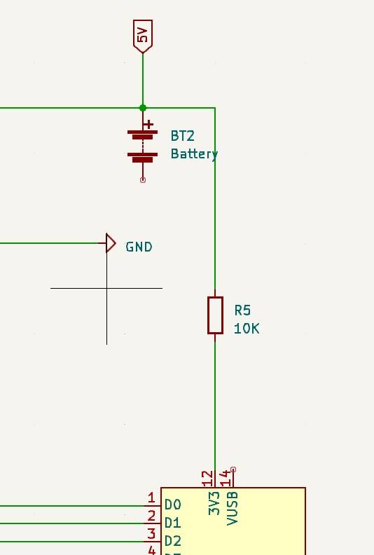
I need to convert my voltage from 5 to 3.3v. I can use a step down module or resistors, or a diode. Before I’ll know what to use. I need to know the specifics of my power supply. But I’ll worry about this later. I don’t have much time left.
Okay. I’m pretty happy with the result.
Perform electrical tool check
To check if everything is correct I’ll run the perform electrical tool check. I get a lot of errors.

The following error occur. - Input Power pin not driven by any Output Power pins - Pin not connected
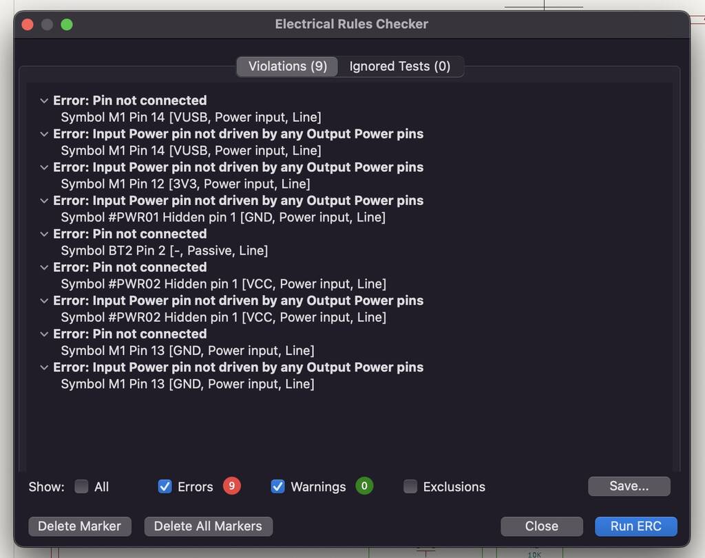
I solved all of the errors exept two. Ther errors aI solved had a simple solution by adding a no connection flag or deleting it. But my GNG and 3V3 connection is giving a error.
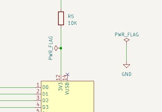
By telling KiCad where the power comes in by adding a PWRFlAG to the wire it resolves the error.
Assign footprints
Where almost ready for the PCB stage but first we need to assign PCB footprints to schematics symbols. This can take a couple minutes. Where likely to get an error know because we added a new component.
We get the following error. We click yes and see what will happen.


Okay, I’m missing a lot of footprints. Now I find out that my BOM isn’t complete at all. Why? Because I don’t know which compononents I have to declare. I should take a look in the BOM file of fab acadamy. What are the components that we have in store.
You can check out ‘view selected footprint’ to see what the component looks like. Still it doesn’t make a lot of sense to me.
I’m not sure why but I can’t find the component that I added.
Starting over
OOOOHHhhhhh noooooooo. Kicad shutted down for a unknow reason aand I didn’t saved it. Super duper stupid. I have to start again.........................................
Okay. let’ss gooooo.
I could’t download the library file for the joystick. Not sure what to do…
I’m not finished and not happy with the result. There are still a lot of questionsmarks I have to cover. But we need to going. Sometimes I like spiral development you know.
I’ll follow this tutorial to help me out with my PCB design.

Continue with this tutorial
I give up for now. I don’t have time anymore. The endresult is not mindblowing. I admit. But I know what to do in the upcoming weeks.
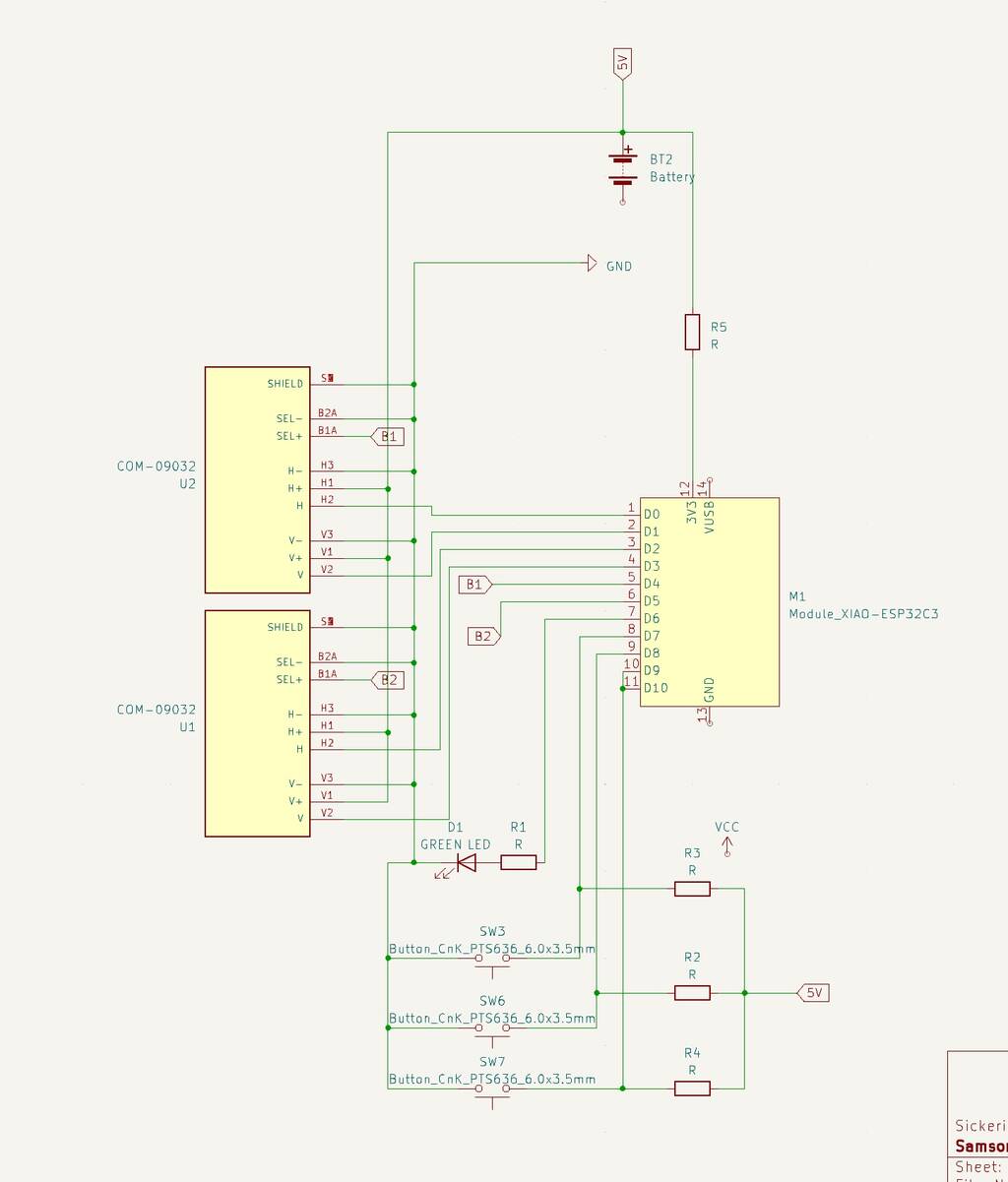
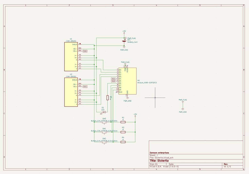
New design
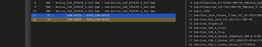
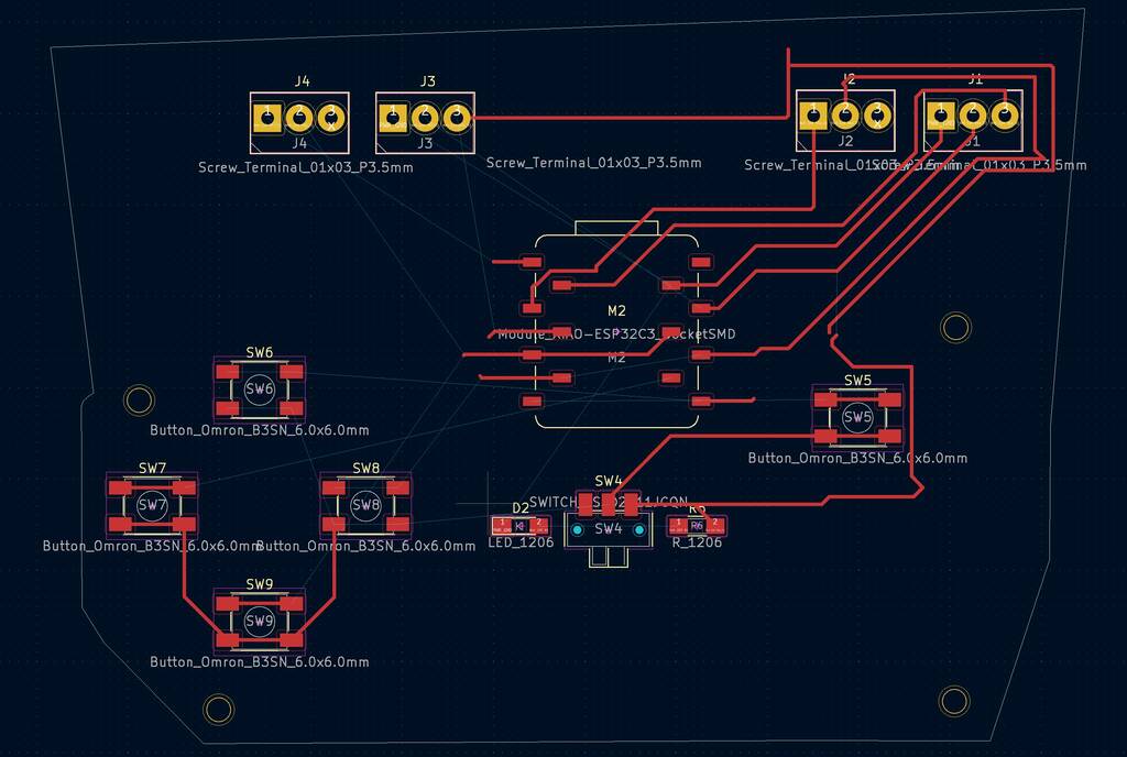
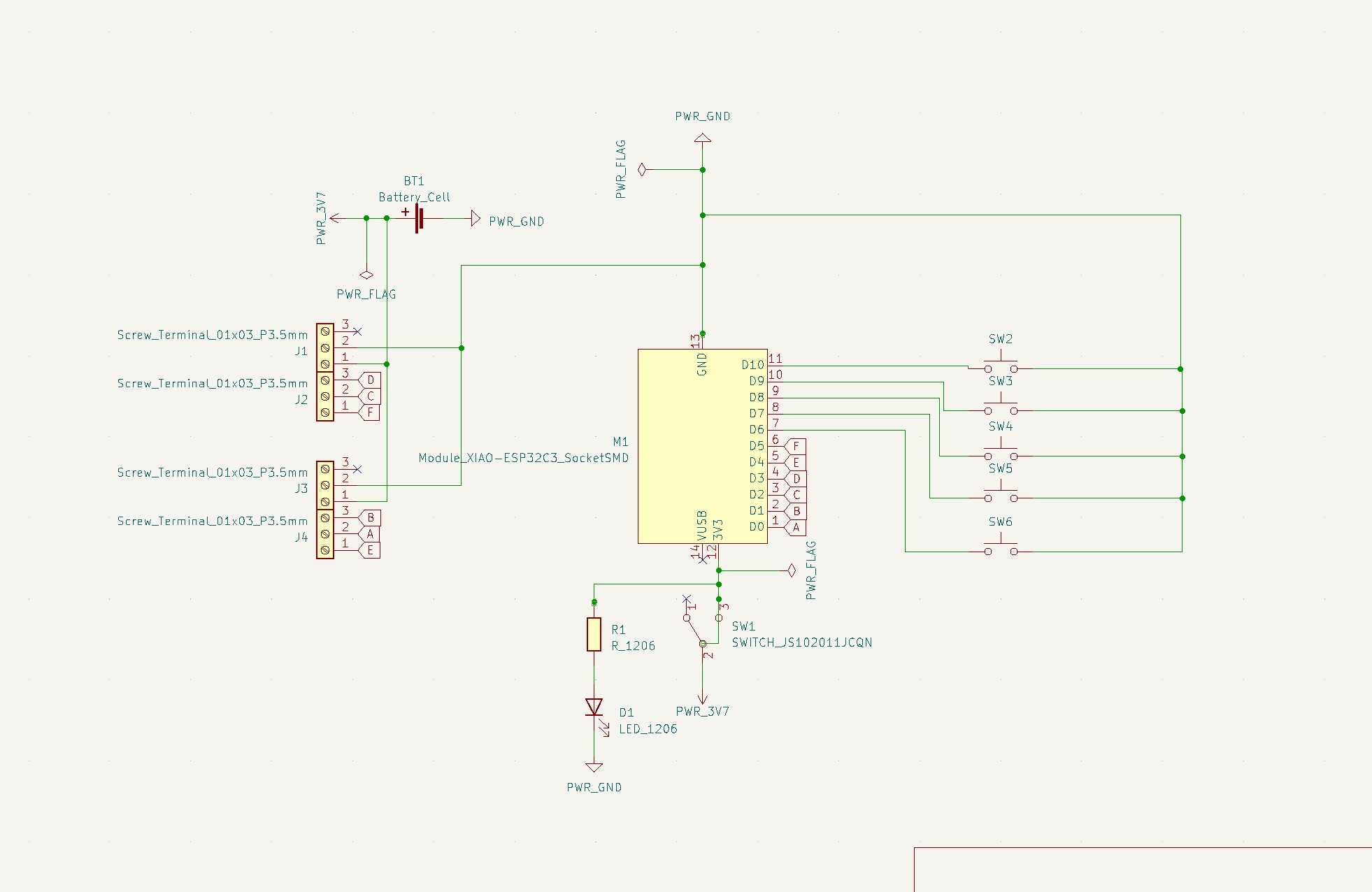
After a lot of struggling with KiCad I decided to make a slightley different board that should be easier to work with. I wanted to intergrate existing joystick modules instead of the weird footprints I wanted to use earlier. The joystick I want to use have 5 output pins that I’ll attach in the screw terminals.
These are the schematics and PCB.

Files
Notes
Questions
where is the component list?
1: schema tekenenen in KiCAD
2: Which components?
- xiao esp32
- led
- push button
- Servo motors
- Joysticks
- Bluetooth
-
AGW wire. amount of gauge -> amount of AMP
Erwin college
- A circuit ia a closed loop where elctrons can flow.
stroom = Volt
spanning = I, Ampere
resistor = r, ohm
Capacitor = C, farad
Hoeveelheid lading op capacitor = Q
frequentie = hertz (uitzoeken)
Water analogy
(vermogen)Power=V*I
polarity= geen ingang geen uitgang
R=V/I
1/0,01=100 1/tijd=frequentie(hertz)
Diode en Led = one-way valave
transistor werkt met spanning MOSFET werkt met stroom
Gebruikte motoren aansturen met controllers
Symbol link Footprint
I hate this. You have to do the following.
download symbol and footprint. I use Snapeda
Create a new map for your footrint. This file is name_mod

Manage symbol libraries In sketch editor.
And manage footprint librarie in PCB editor.
Import the symbol in sketch editor. Run electrical tool check and click ok. It find the footprint now.
Prepare image
create in F.cu the traces.
Create the oultine (and holes) in margin -> take drill diameter into account.
Open both files in same file in inkscape. Make sure cu is centered in margin. use control shift R to crop canvas.
Save margin and CU separate.
Things I’ll do different this week.
Start with a Hero shot Finish my documentation on teusday