8. Electronics Production
(Hero) shot
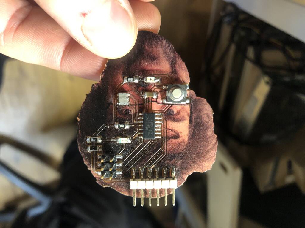
My first shots weren’t Hero like. I made a lot of mistakes and it took ages before I had my board milled.

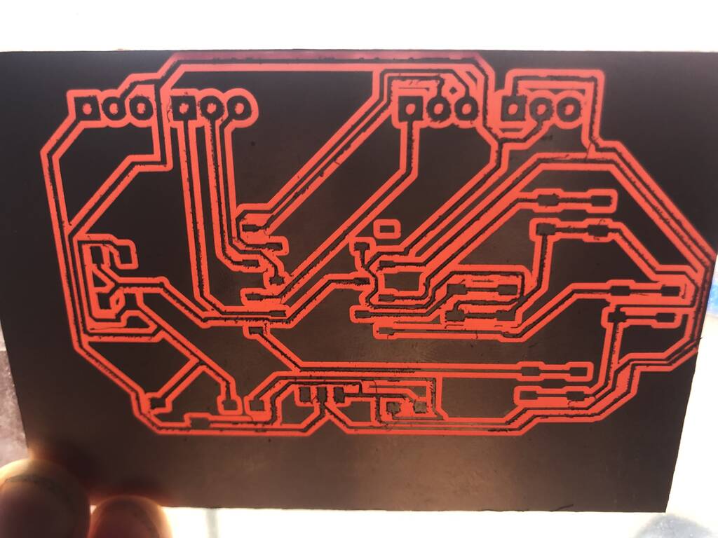
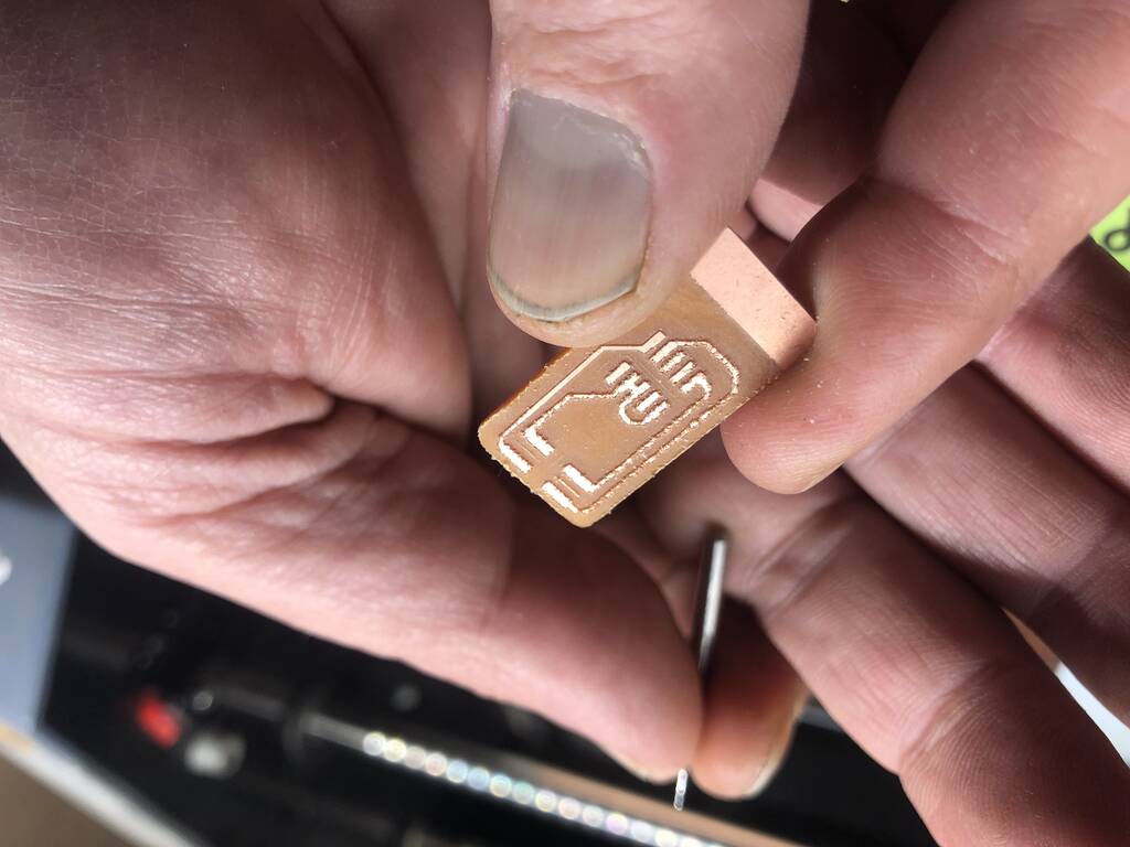
This look more like it!
Assignment
Group assignment:
Characterize the design rules for your in-house PCB production process: document feeds, speeds, plunge rate, depth of cut (traces and outline) and tooling. Document your work to the group work page and reflect on your individual page what you learned.
Individual assignment:
Make and test the development board that you designed to interact and communicate with an embedded microcontroller.
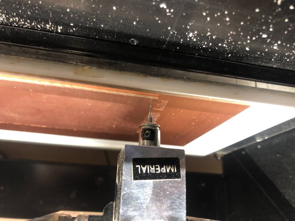
Milling machine
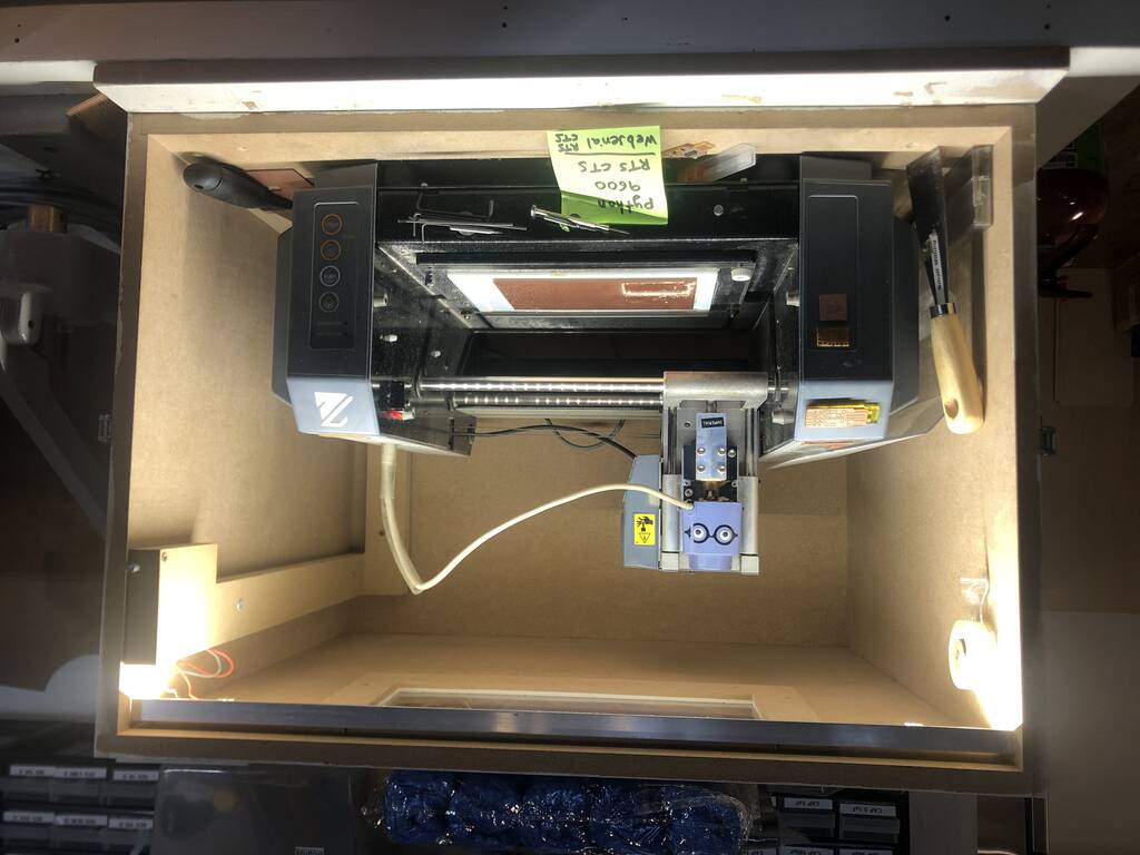
Roland modela mdx-20 milling machine
This is an old machine that our Fablab bought second hand for around 2000,- euro’s. You can’t buy these machines anymore.
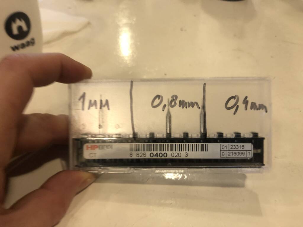
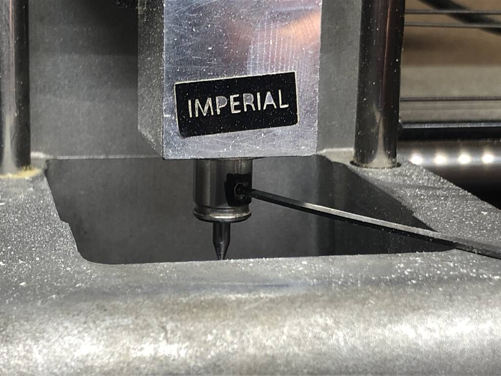
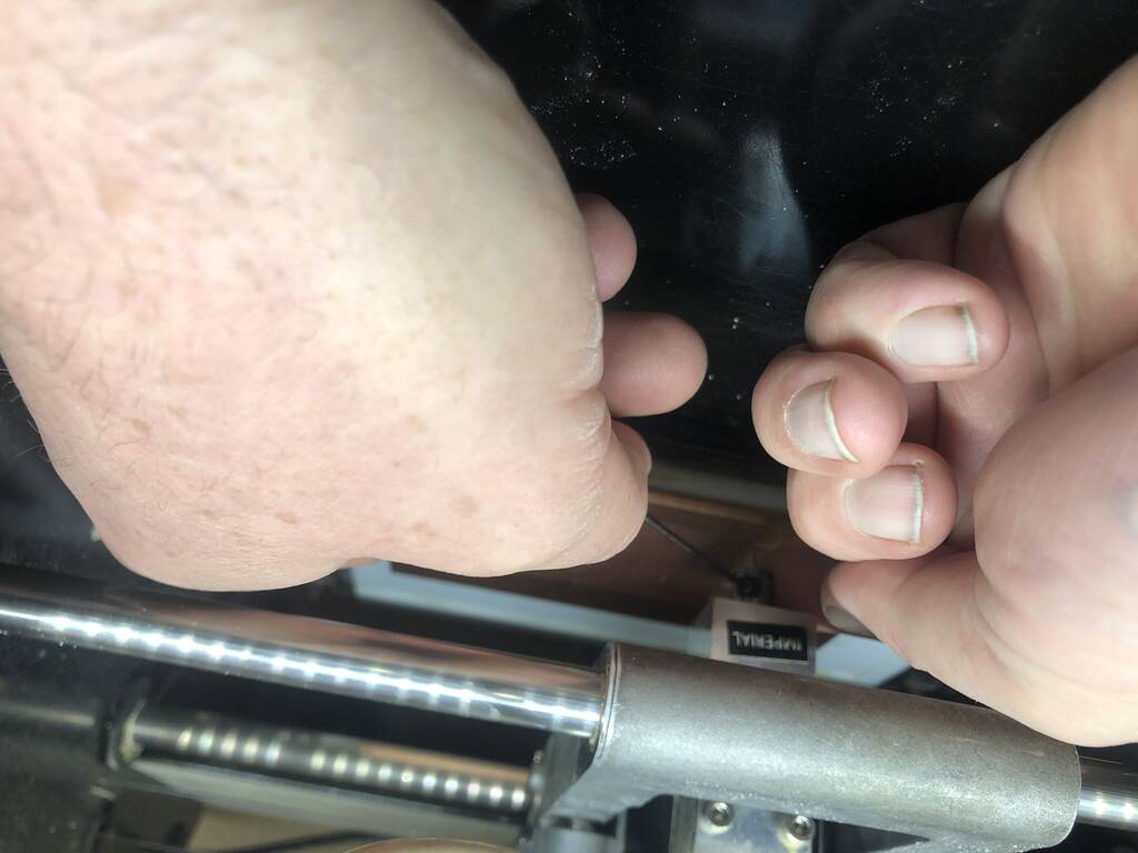
This is a conical mill end from titanium.
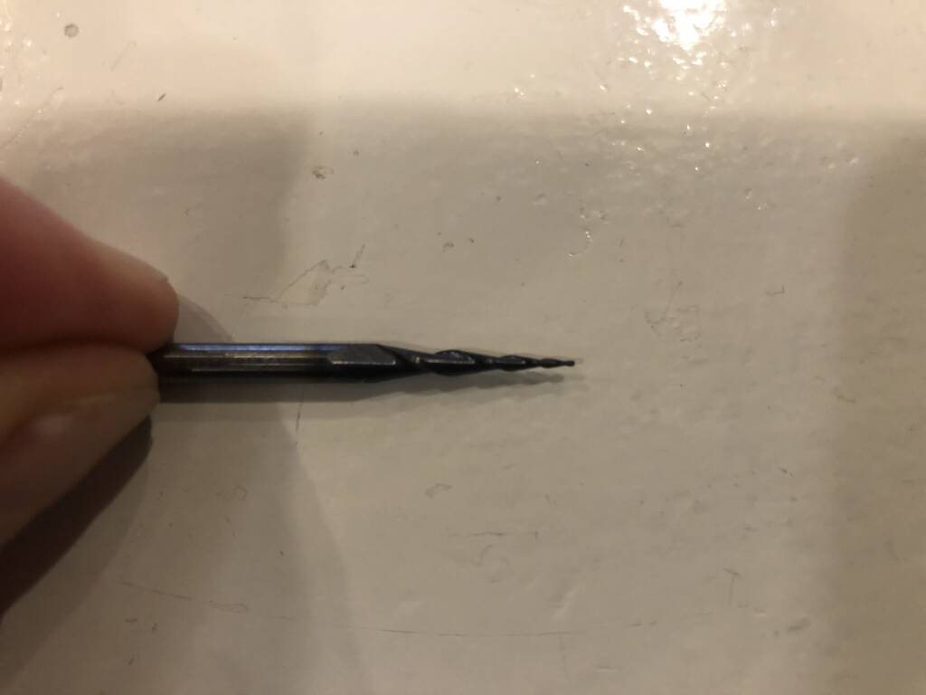
We’ll work with the Two flute end mill .4 mm for our traces. That’s pretty small as you see.
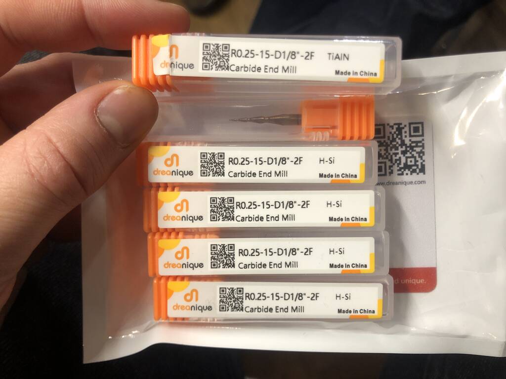
We’ll work with the Two flute end mill .4 mm for our traces. That’s pretty small as you see.

1mm en .8 mm we use for cutting out the pcb’s.
This is the Henk special.
The milling bed exists out of 3 layers. The transparant layer. The white layer, which is milled with a surface bit and the sacrificial layer. On top of the sacrificial layer you tape the board that you will use for your PCB.
This is the sacrificial layer.

Te greenish material is a: Fr4 board. It’s not recommended to work with this because it’s carbon fiber. The dust residues are toxic.
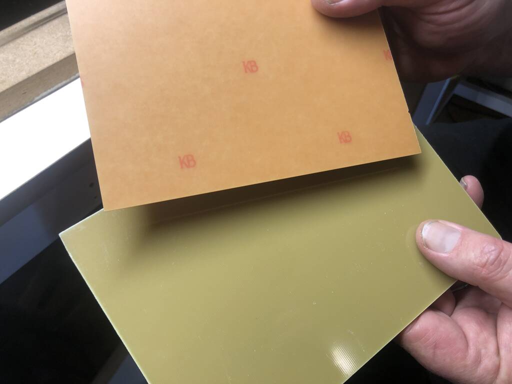
Here you see Henk place the fr1 board in the corner where the surface is smooth. This is de first board. You won’t mill in this board!!!!
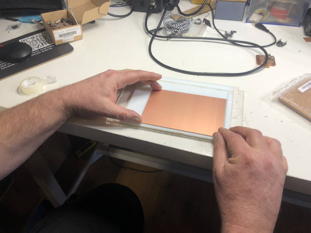
Make sure the tape doesn’t overlap. Thus will cause an indifference in hight. Always stick the tape over the sides. If the end below the plate it could
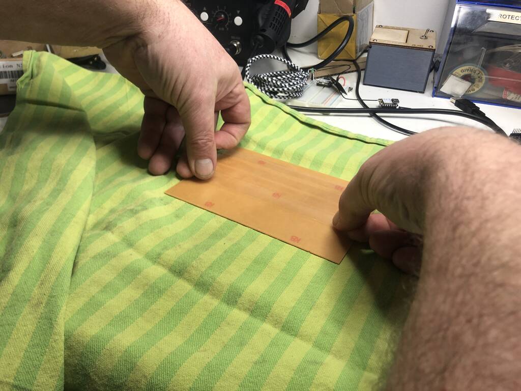
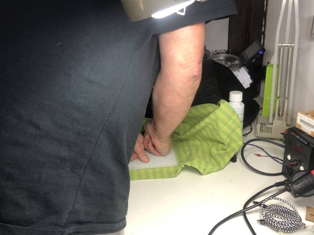
Henk presses the sheet down.
Henk cuts the sides.

Never stick the model where you’ll mill in exact in the corner. This will prevent a lot of hassle when taking it off.

Henk checks if the thickness is the same on all the sides.

There are two set screws the one marked you can take out.
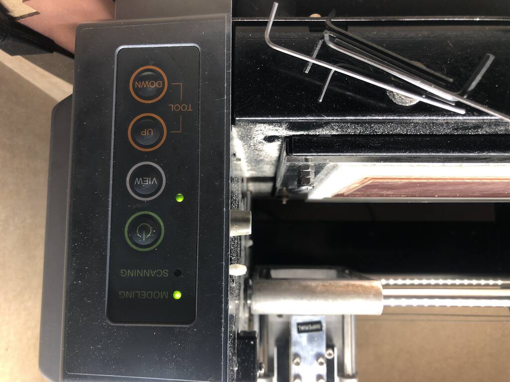
START THE MACHINE
Press the on button. Press view to take it out the view mode.
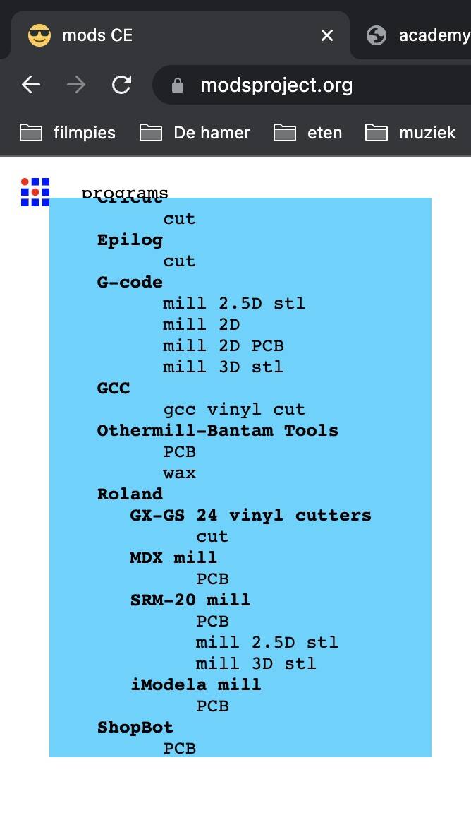
MODS
PROGRAM - open program - pcb -
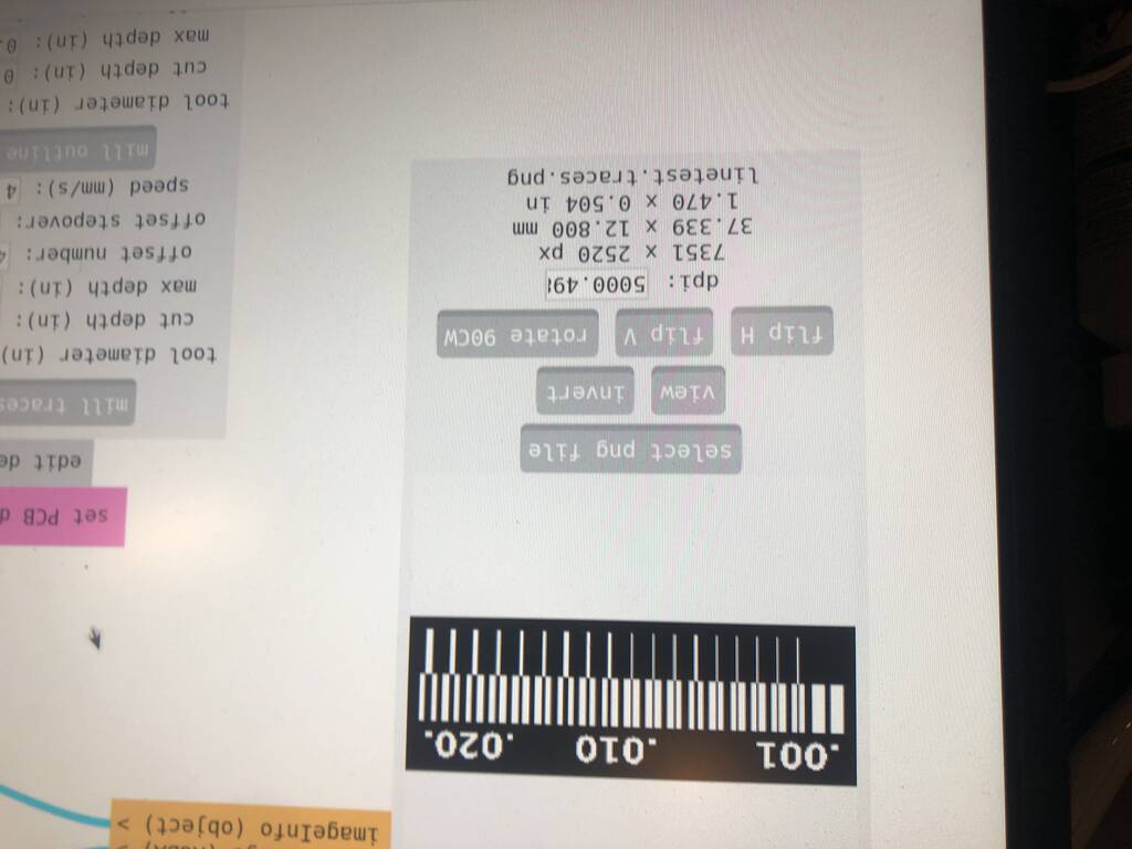
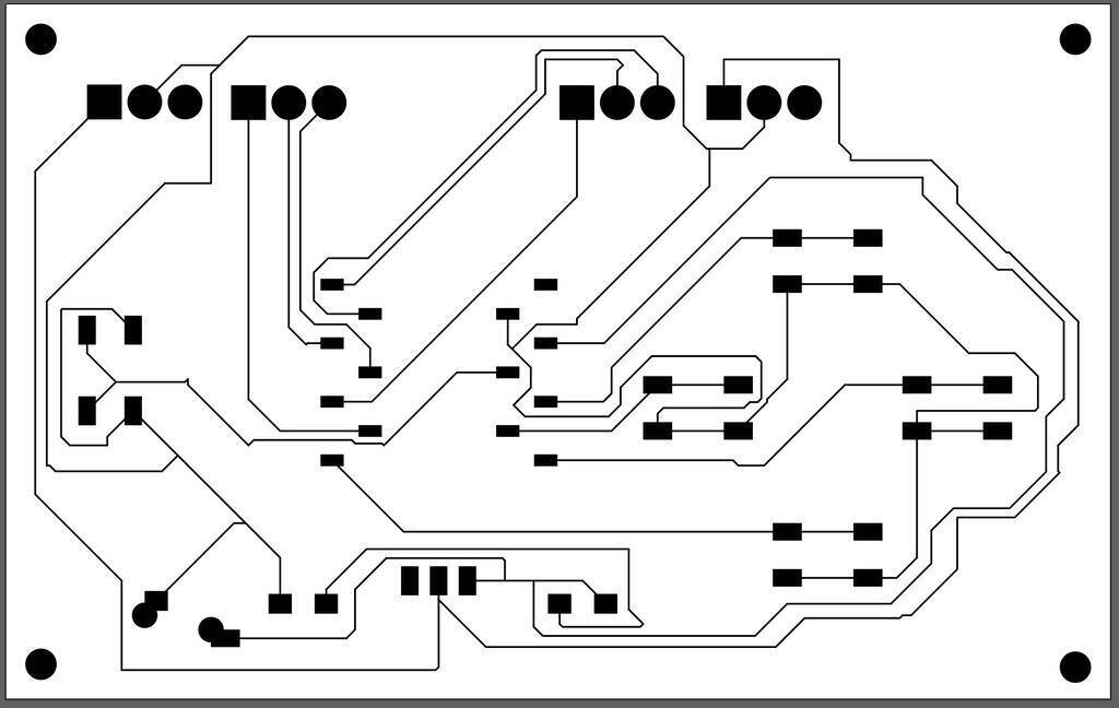
We’re going to run this test. The left is a 1000 inch. This is a PNG image. Remember Mods can’t run vectors. SVG would be also possible.
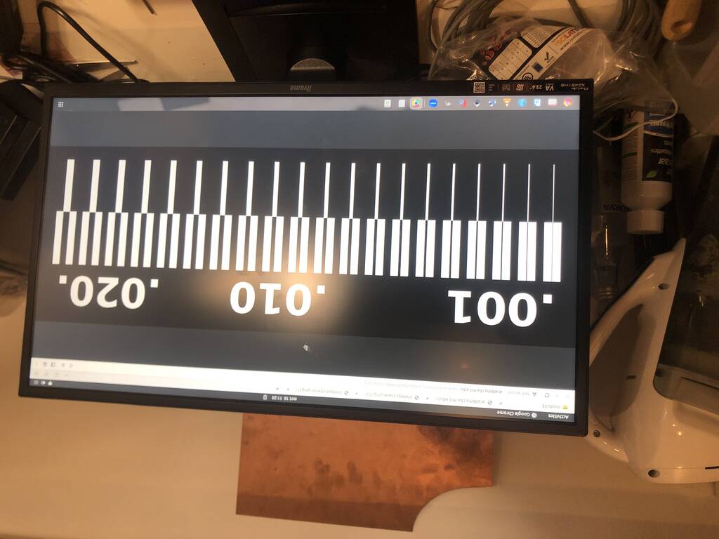
This image is ca 5000dpi. That’s enough to mill precise.
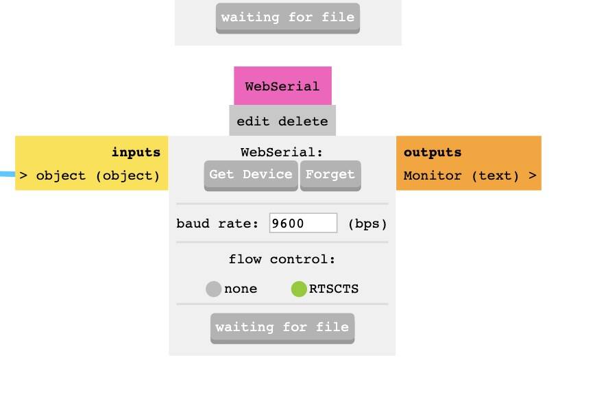
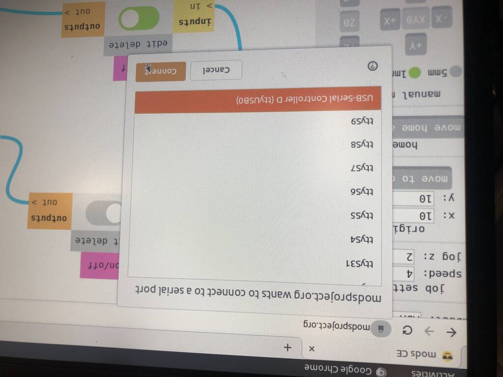
Make sure to connect the machine. You should do this manually
The Z axes you bring in position manually. It stops eventually. Bring the mill up in the Z direction with one push.
Lower the end mill bit til it falls on the material. Now the machine has space in the Z axes to mill in the material.
Remember the origin. Always make a photo.
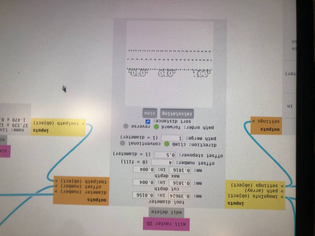
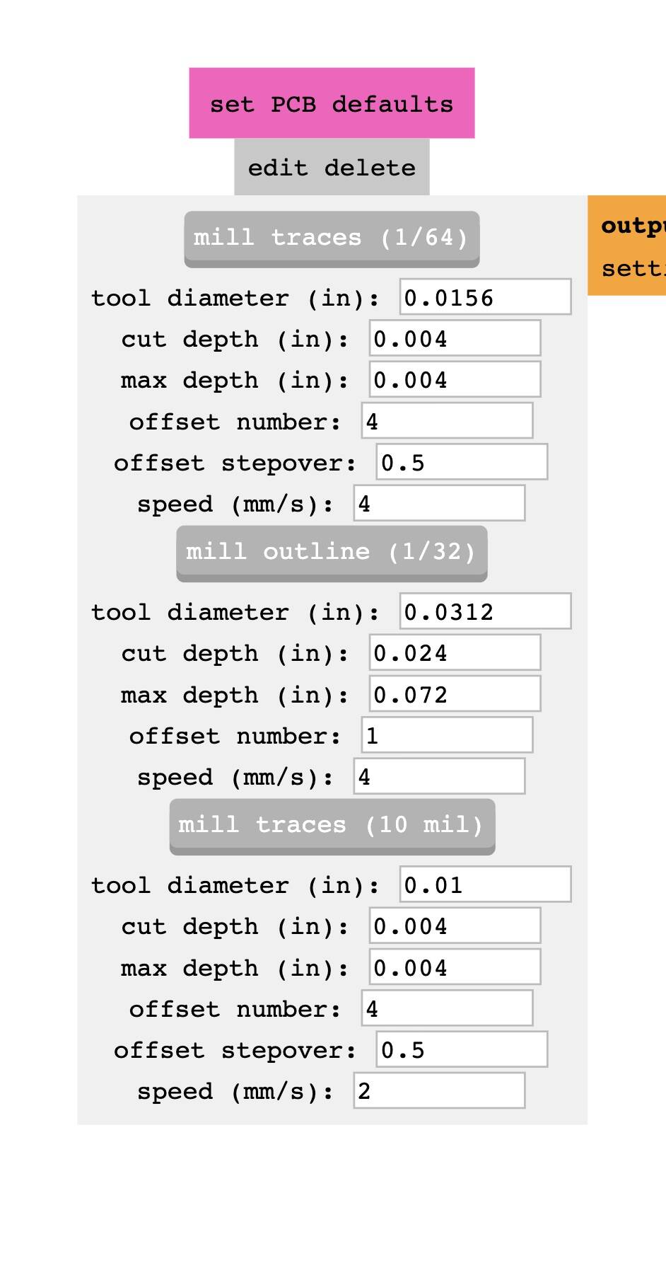
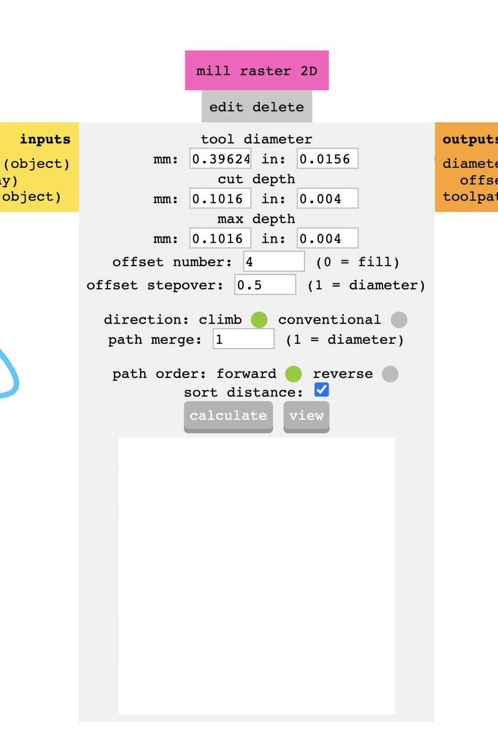
Mill traces is for the traces. Mill outline for the outline. If you click on the wanted option it calculated it autmatically to the mil raster 2D.
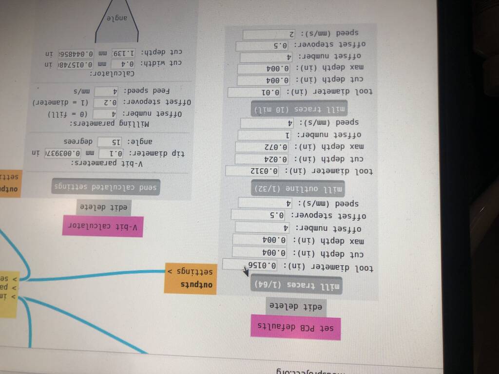

Adjust cut- and max depth. 0.004 inch is a good dept for the traces.
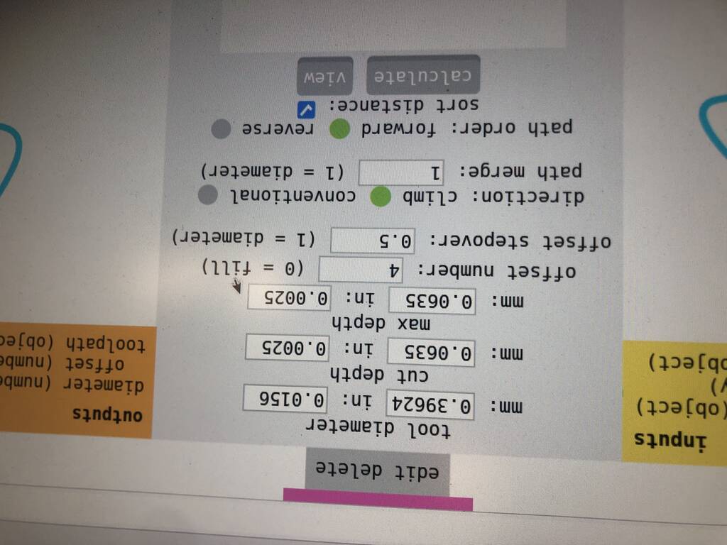
The offset number is the amount of track the mill will mill around the traces.
Press on the calculate button.
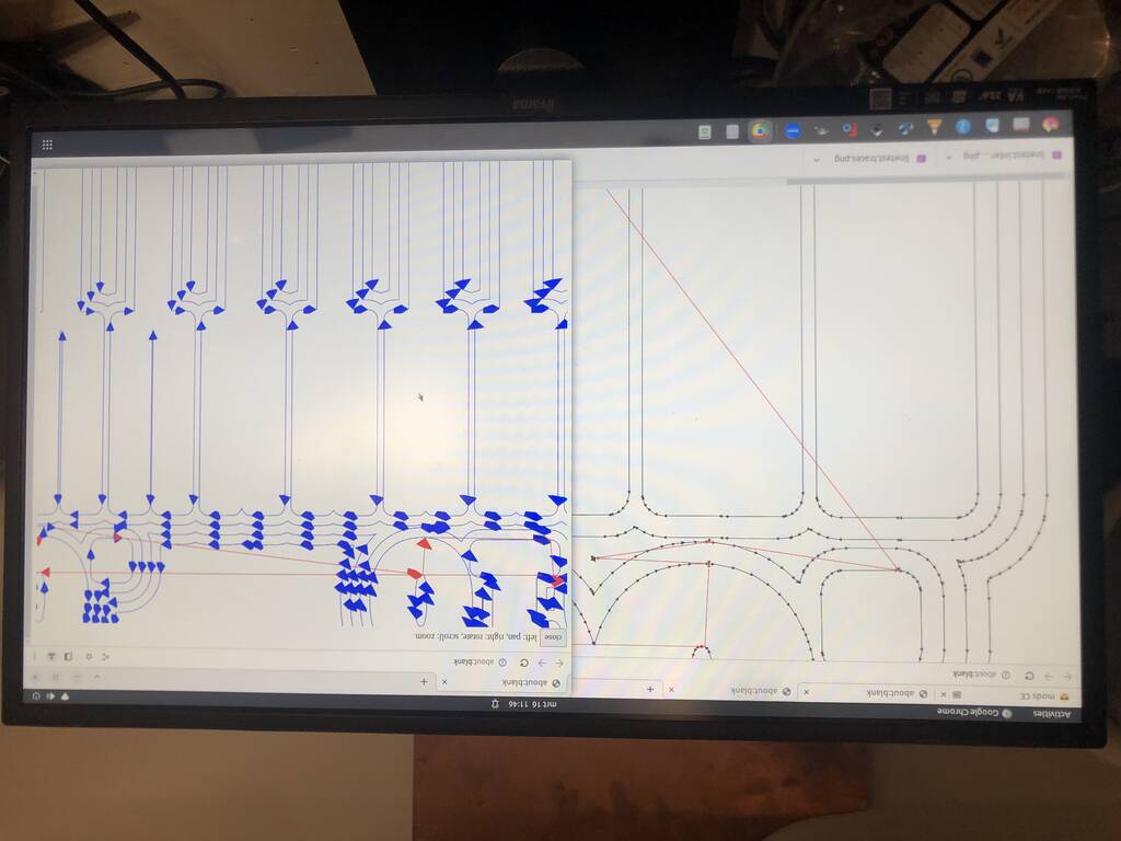
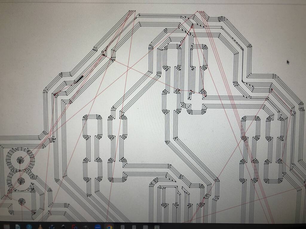
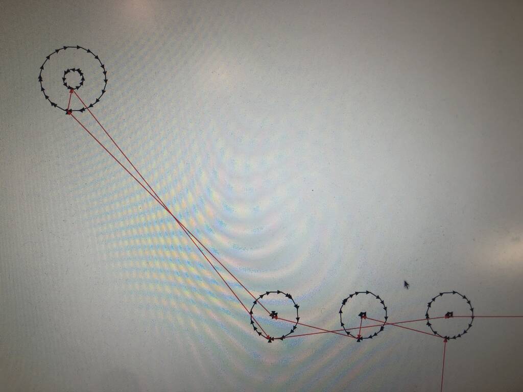
You can see which line of the imported PNG the mill can mill. The really small ones are not able to be milld.
Blue is the mill line Red is the trace in the air.
When the origin is ready. Press calculate.
This is the result of the botton sheet that is crooked. Henk adjusted the screw on the right hand side. Pressed view and then it continued.
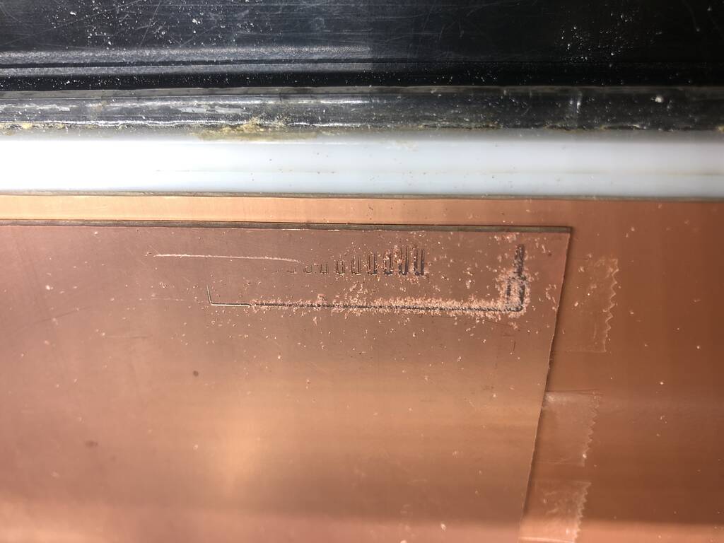
The cut depth is really tight. So we adjusted it.
If you want to cancel the mill job. Turn off the machine. Cancel the chrome browser where Mods is running. Turn the machine bank on. Press up and down at the same time for 10 seconds and wait till the view button stops blinking. Now it should be ready to calculate and send your new design to the mill.
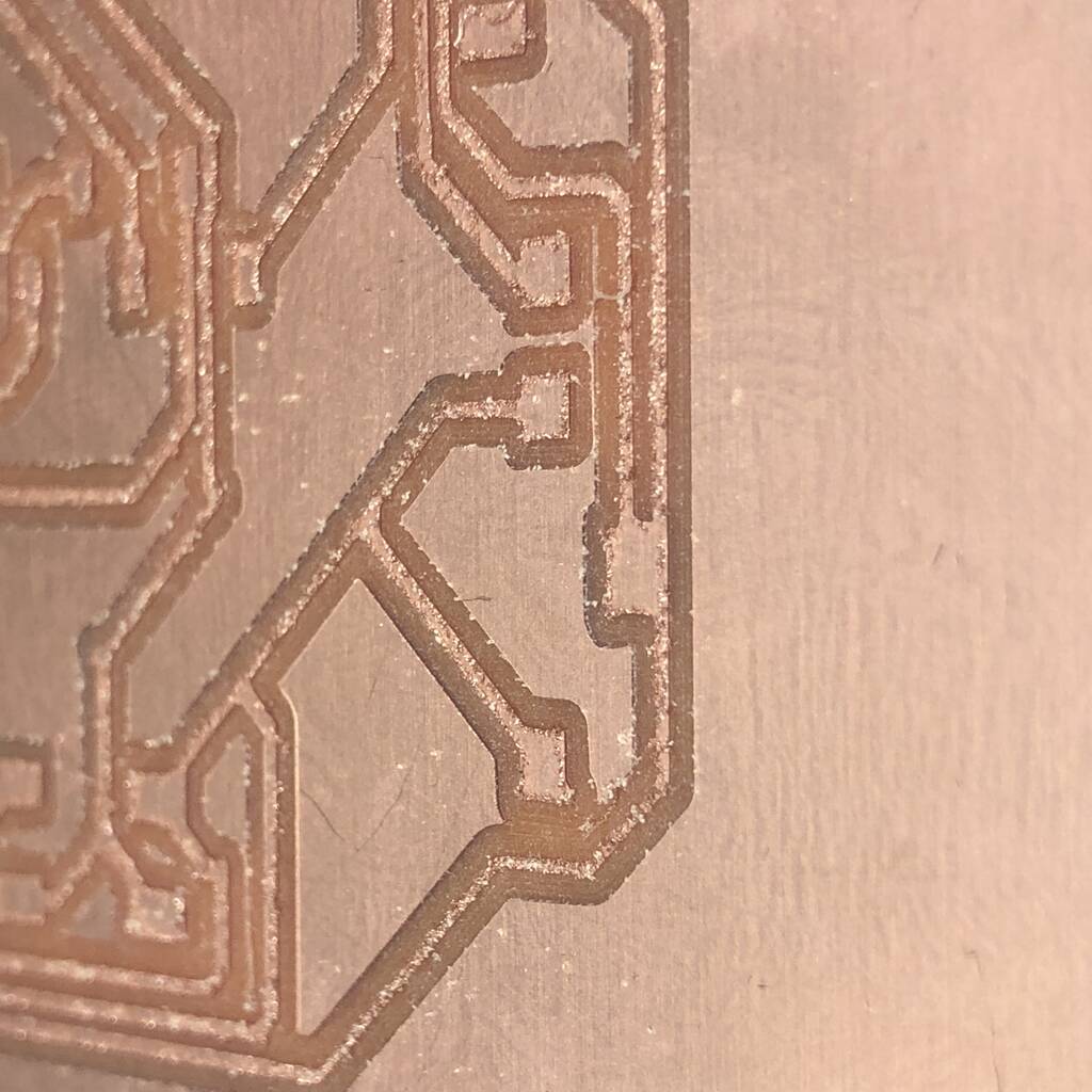
This is a result of a good mill job that’s done.
After the mill job vacuum the residues.

For cutting out a outline go for a .8 mm drill.
If you stick you screwdriver in it should move.
Group assignment
Group assignment:
Characterize the design rules for your in-house PCB production process: document feeds, speeds, plunge rate, depth of cut (traces and outline) and tooling. Document your work to the group work page and reflect on your individual page what you learned Individual assignment:
For the group assignment we imported two files to test the accuracy of the milling machine. You can find the files below the header Cam on this (page)[http://academy.cba.mit.edu/classes/electronics_production/index.html]
This is the trace.

This is the outline.

Michelle and Pieter milled with 3 different mill bits on the Roland Modela. And one board on the ........

Kicad design
I’m starting with a new design since my last was not smartly designed. I want to make a joystick so I can controll my tentacle.
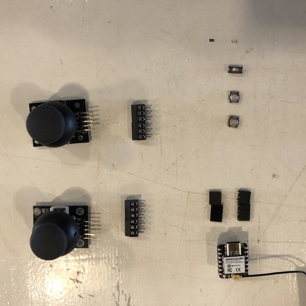
Components
List of components that I will use.
| component | amount | data sheet |
|---|---|---|
| Socket smd for ESP-3C Xiao | 1 | Fab library |
| 3pin screw terminal for joysticks | 4 | Fab library |
| Switch slide | 1 | switch |
| Led green | 1 | led |
| push buttons | 5 | Push button Omron |
| resistor 100 ohm | 1 | Fab library |
| ESP-3C Xiao | 1 | Fab library |
| Joystick | 2 | Joystick |
| 3,7 V, 380mah battery | 1 |
Info about the components
What type of resistor do I need for my LED?
I have a 3.6V 380mah battery.
Resistor = (Battery Voltage – LED voltage) / desired LED current.
R = (3.6 - 2) / 0.02 = 80 R = 80ohm
Joystick
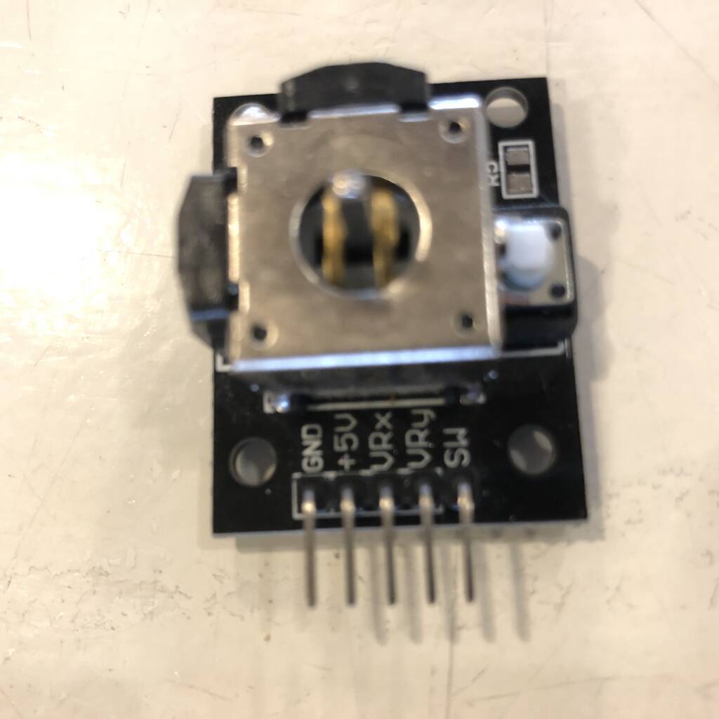
GND is the ground pin.
VCC provides power to the module. Connect this to your positive supply (usually 5V or 3.3V depending on your logic levels).
VRx is the horizontal output voltage. Moving the joystick from left to right causes the output voltage to change from 0 to VCC. The joystick will read approximately half of VCC when it is centered (rest position).
VRy is the vertical output voltage. Moving the joystick up and down causes the output voltage to change from 0 to VCC. The joystick will read approximately half of VCC when it is centered (rest position).
SW is the output from the pushbutton switch. By default, the switch output is floating. To read the switch, a pull-up resistor is required so that when the joystick knob is pressed, the switch output becomes LOW, otherwise it remains HIGH. Keep in mind that the input pin to which the switch is connected must have the internal pull-up enabled, or an external pull-up resistor must be connected.
GPIO = A general-purpose input/output is an uncommitted digital signal pin on an integrated circuit or electronic circuit board which may be used as an input or output, or both, and is controllable by software. GPIOs have no predefined purpose and are unused by default.
This is a really cool link if you’re interested to find out more about joysticks.
buttons
My buttons need a pull-up resistor. All the GPIO pins have an pull-up resistor.
ESP
The XIAO ESP32C3 is capable of using a 3.7V lithium battery as the power supply input.
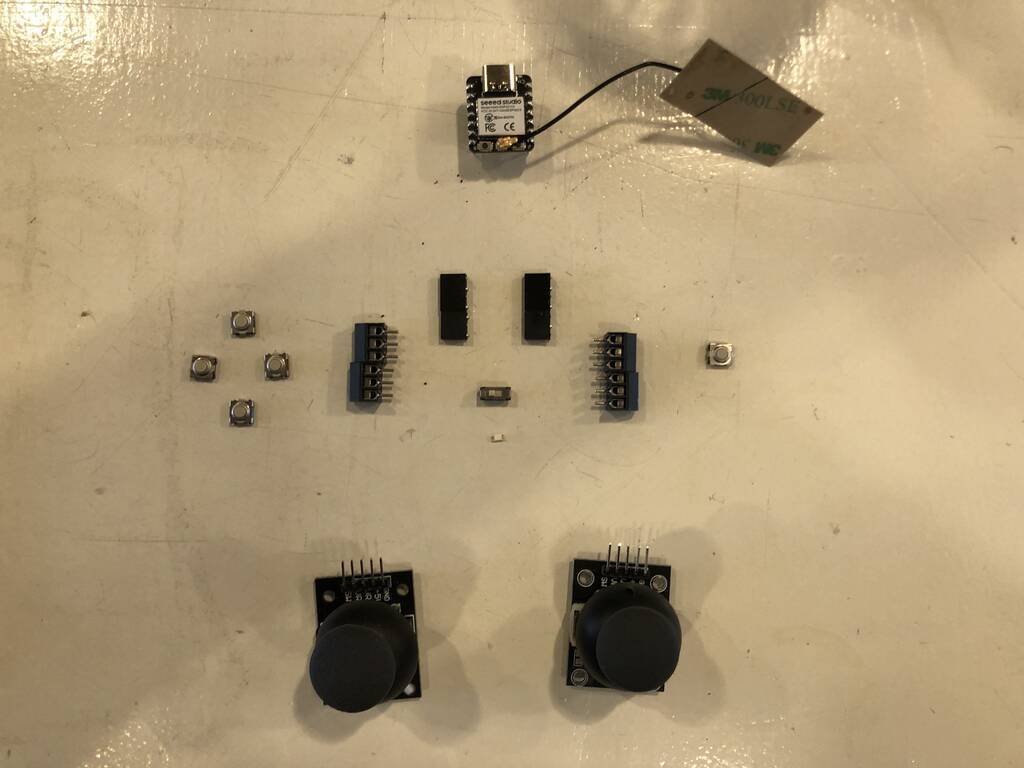
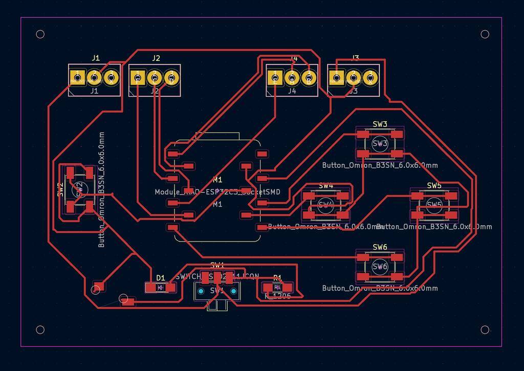
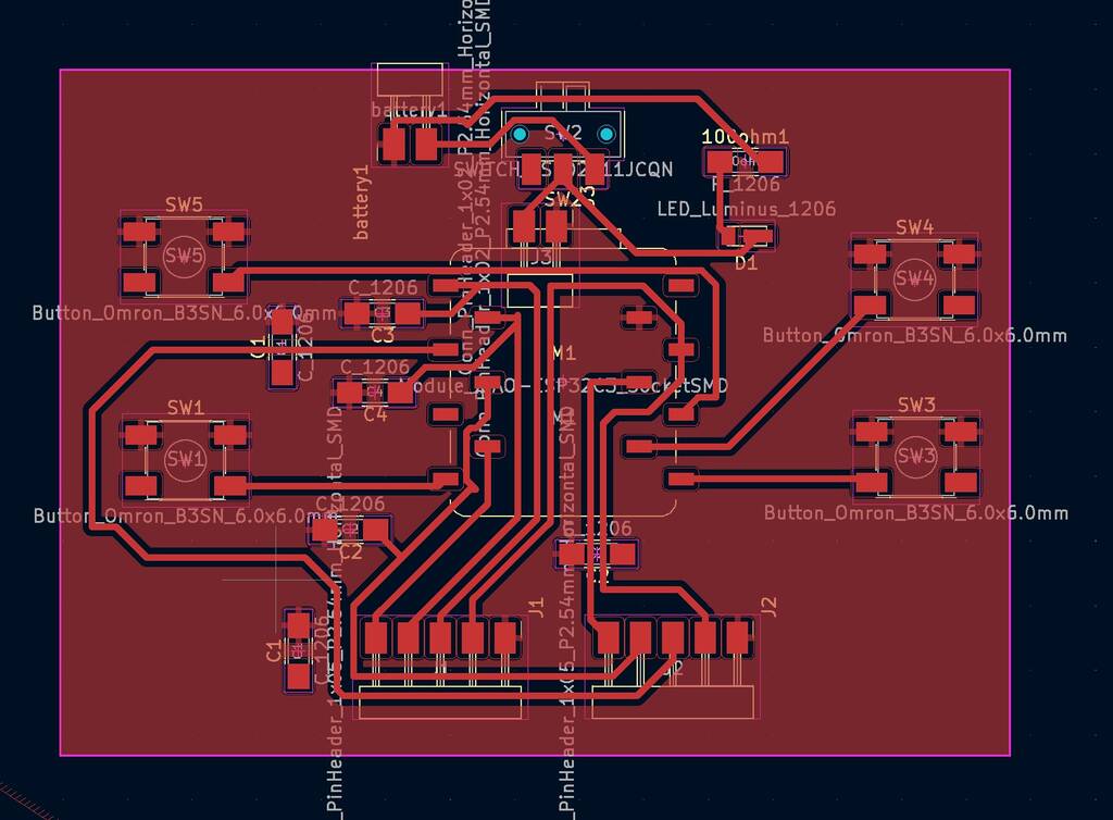
Design
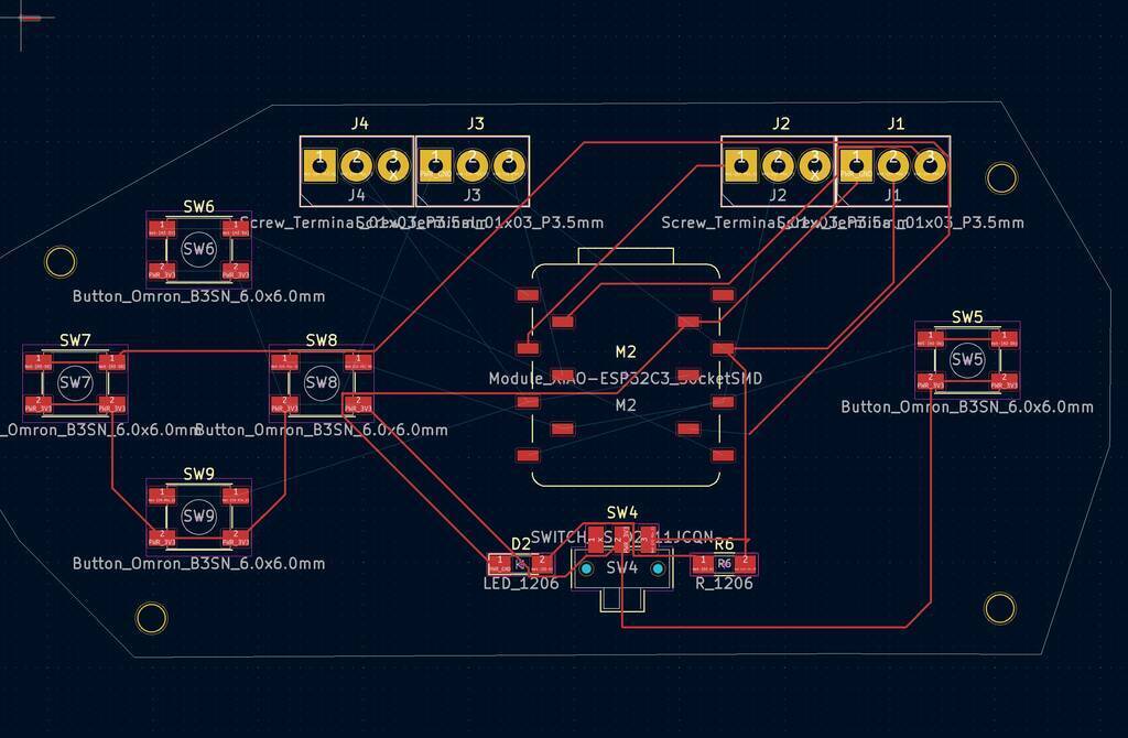
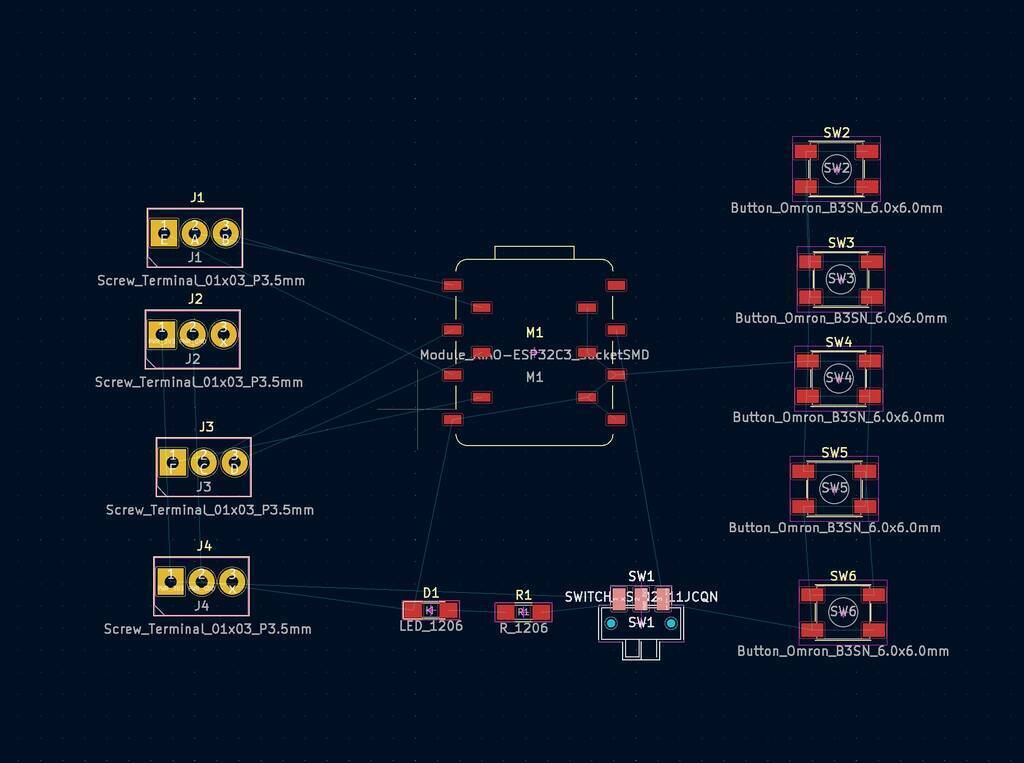
Before I started designing my schematics I made a layout with my components.
I had a view pins left and I thought it would be cool to integrate a 4 button controller that can move the tentacle in the x and y axes. Not really neccesary but nice if I could also code this in a later stage.
I connected everything in my schematics
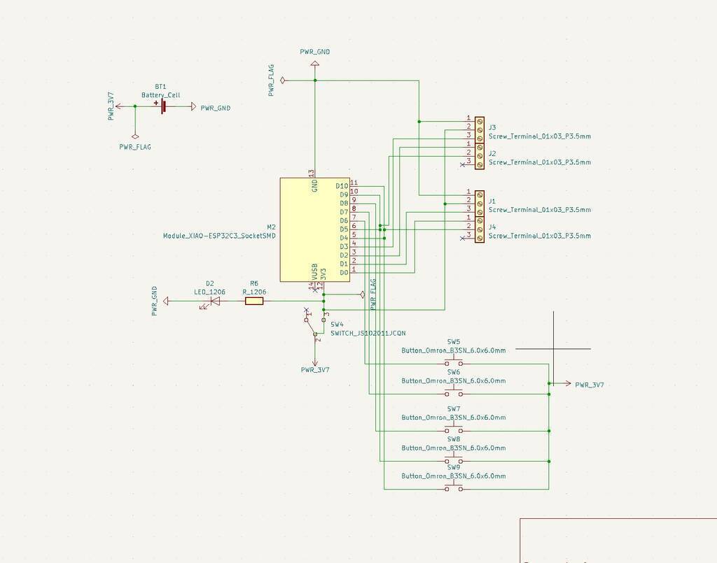
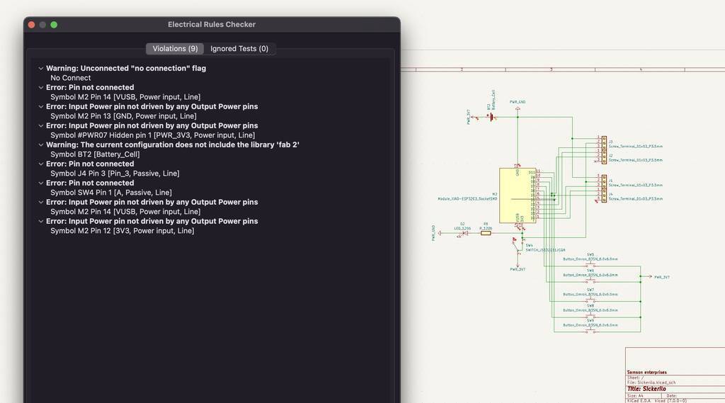
While running the electrical toolcheck I got a view errors that where easy to solve
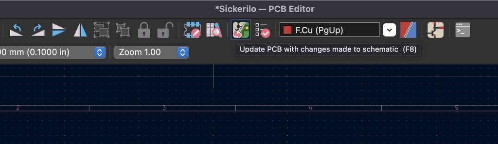
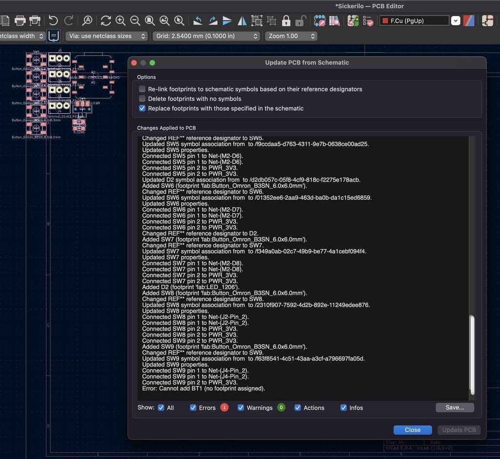
I update my scheme to the pcb editor.
Got a error for the battery. I think I will just mount two holess since I want to solder a battery to it. I placed these holes manually.
Board set-up preferences. I got these set-ups from Nadieh but Michelle told me that nadieh chose for this because something wouldn’t fit with the recommended settings of .40. Since the drill bit is .40 this makes more sense.
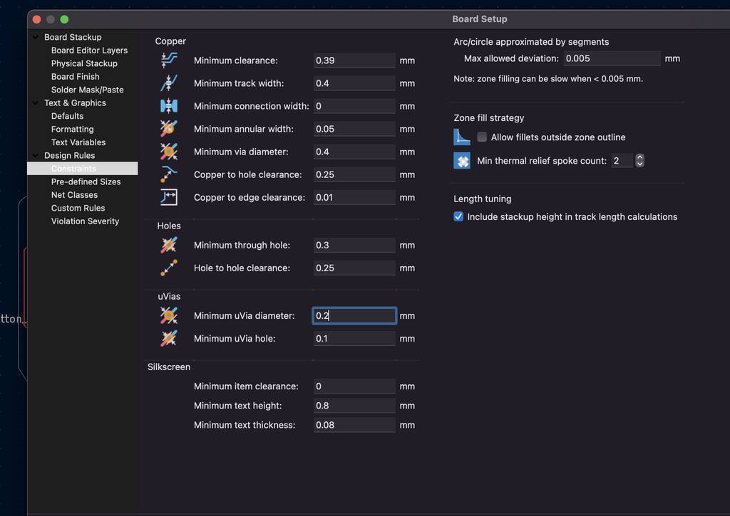
Net classes set-up

I’ll try to make a new design since it’s to messy to make a nice pcb in the PCB editor.
When I copied and pasted the schematic so I could change it, I got a error that my lines are off grid. It’s probably because I changed my board set-up. This can be fixed to right click your mouse and select grid to change the grid settings (I did this in a later in the process).

I thought I would give it a shot to export the file with the error into the pcb maker. When I disable the warnings and solve the errors. It actually looks pretty good. I’ll give it another shot in the PCB editor.
I won’t worry about the battery. These are just two through holes. Don’t forget to add them!!!
Something weird is happening here. Why are all my buttons signed as power and gnd?
Ah, the order of powering my pins is incorrect. I should power them first and then attach them to the gnd.
Like so

This looks better. Only pin 13 is annotated as Gnd. Oh but that’s fine because that’s the general pin output on the board. It’s nice that Kicad tells you what happens on the pins.
I think I got it!
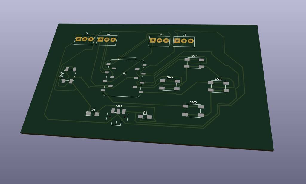
3d viewer
To see how my board would look like I went to the 3d viewer feature. A few things came up that I might want to add and change.
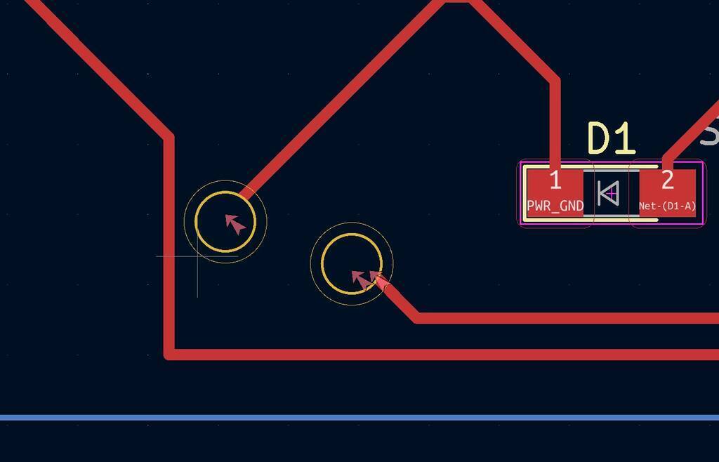
Extra mount holes in the corners of my board so I can attach the board to something. Were are my GND and VCC inputs???
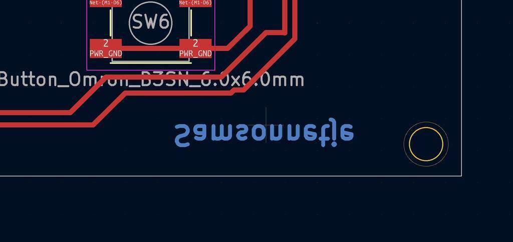
I’ve add 2 mountingholes by hand for my VCC AND GND. I couldn’t connect the holes to the paths but I think this should be okay. I also added my name to the board with the Text T features.
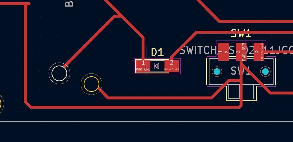
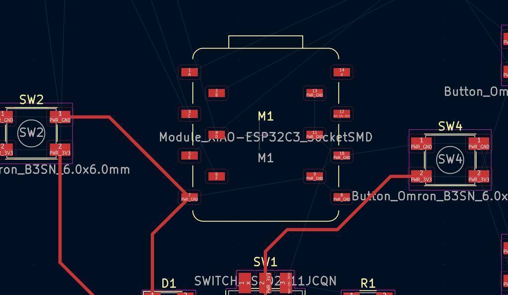
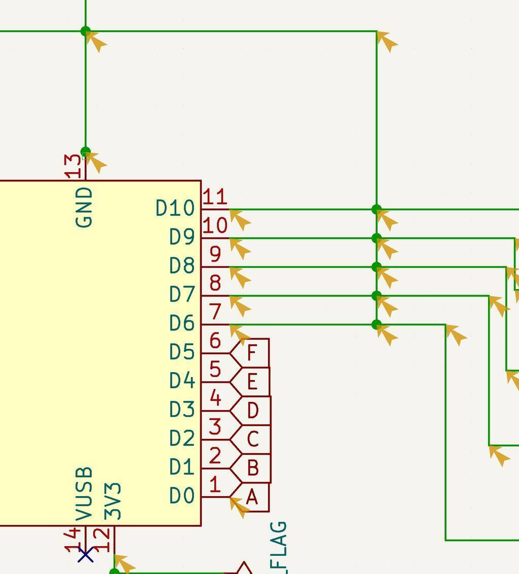
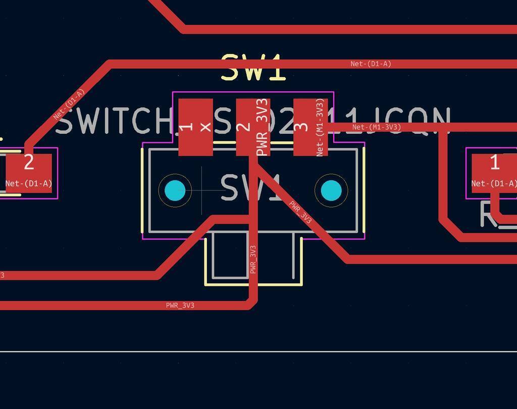
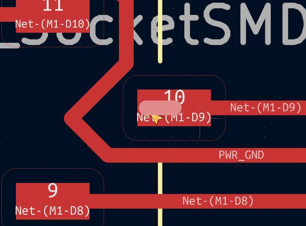
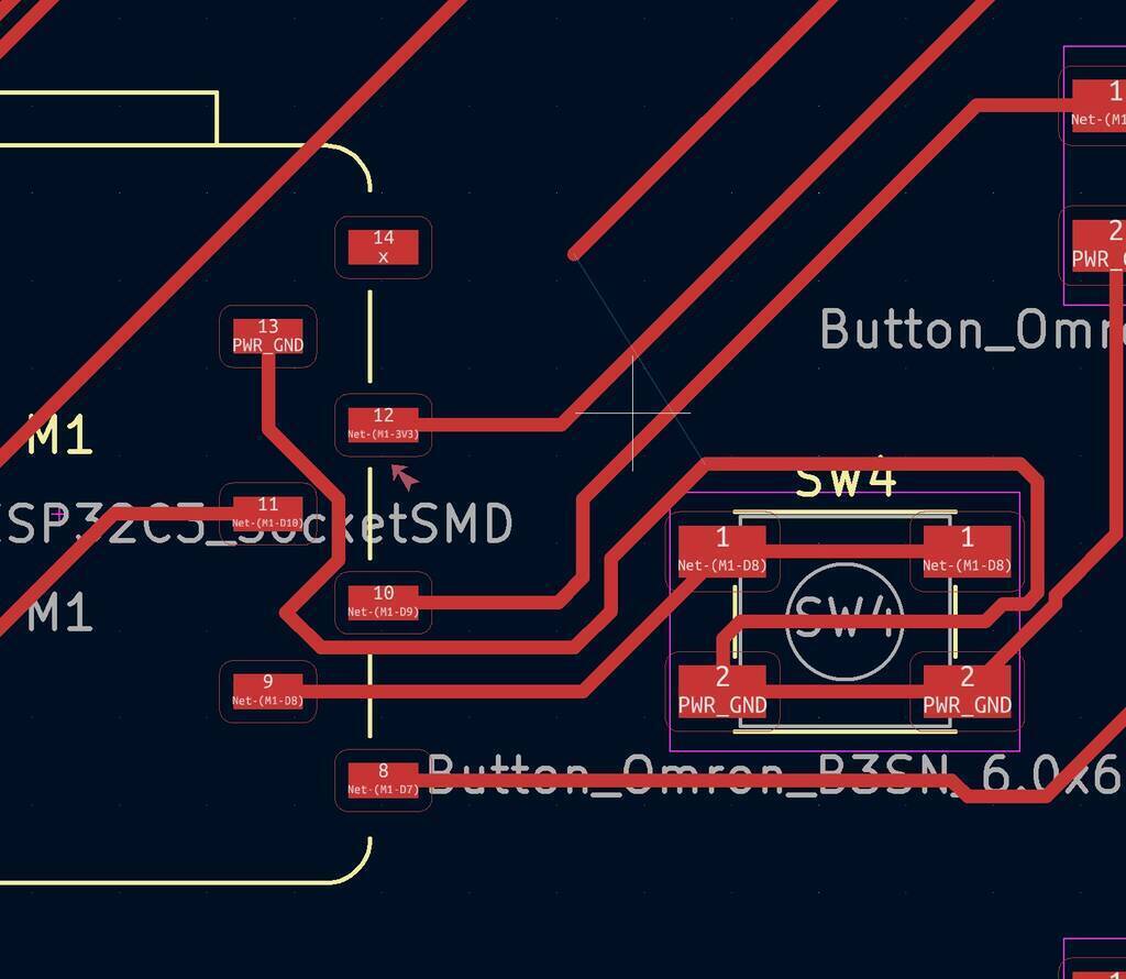
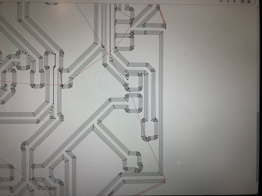
The inputs for my joystick are different because my pcb paths would fit better. Below you see the pin layout of my PCB

Is this correct though? Did I connected the VCC to the right pin? I should check the Data sheet.
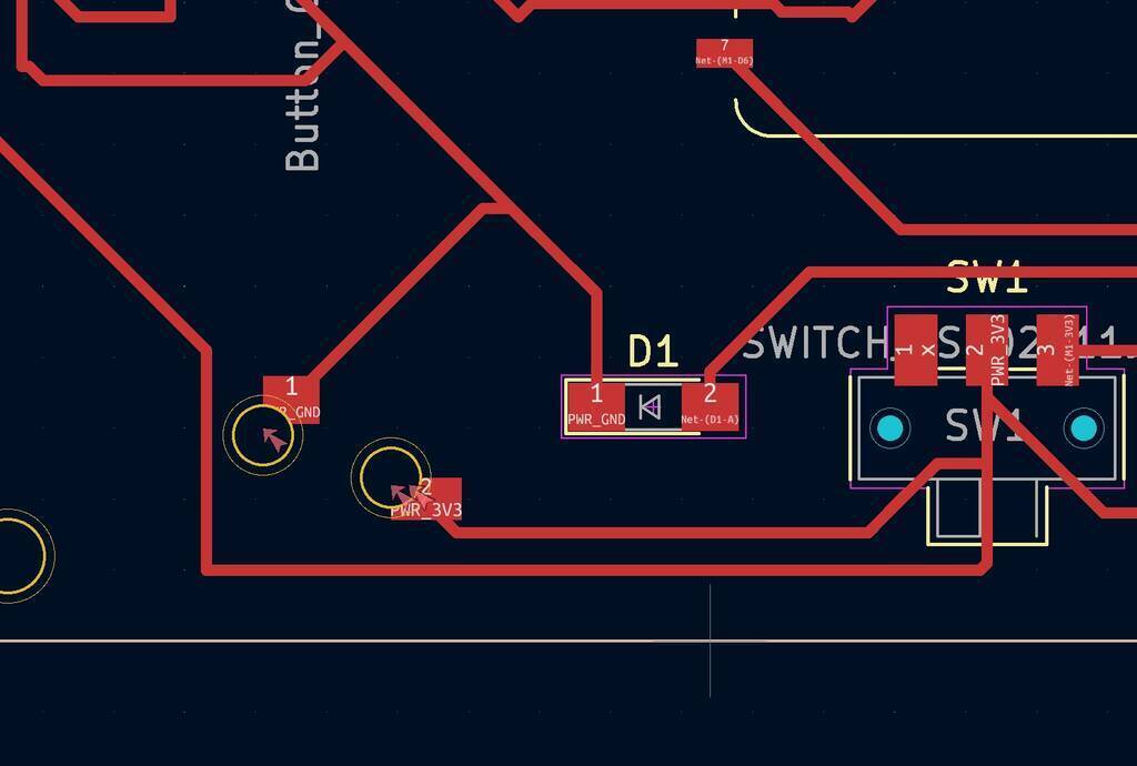
Shit. I think this is the wrong switch..... But after measuring the switch that I have I concluded that it will fit.

Design rule checker
I checked the design rule checker. I got multiple errors and warnings.
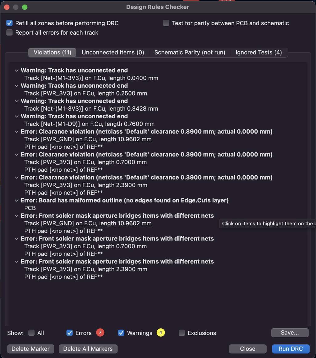
This is probably track has unconnected end.
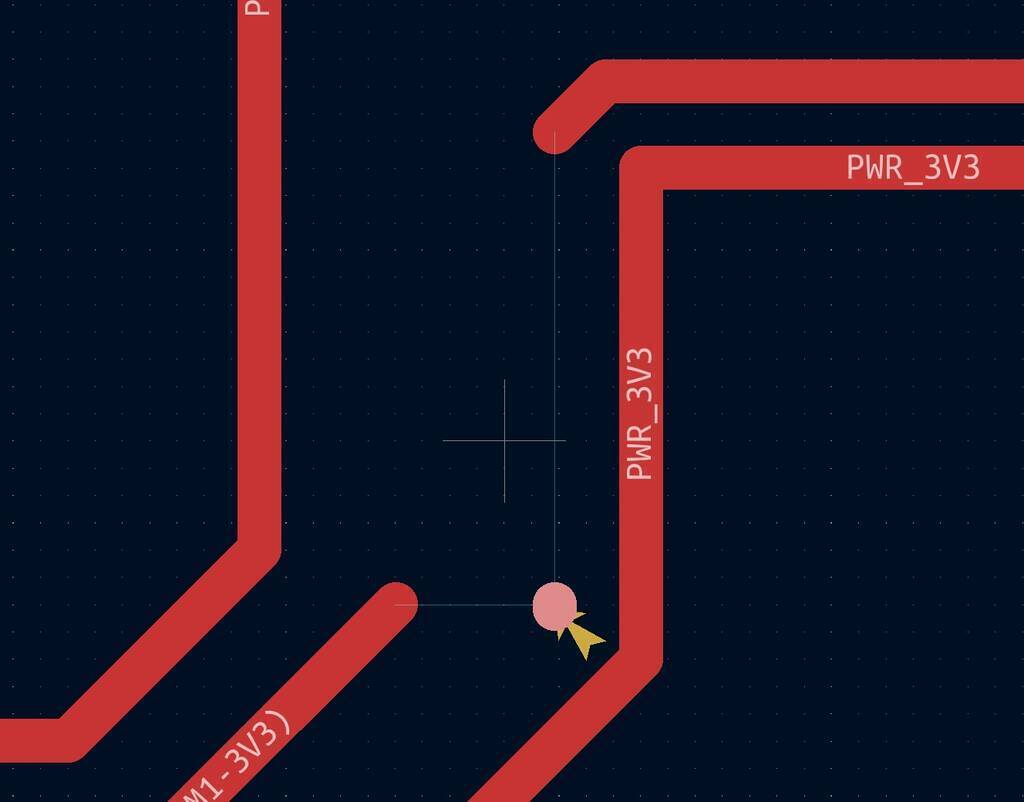
Most of the errors that are found are because of the mounting holes that I couldn’t connect properly because I didn’t told Kicad what it is.
But this fault is weird. Ahhhh. I found it. It’s a little line hiding itself from me.
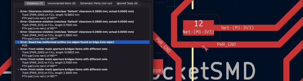
No board found on edge cut layers.
I deleted the line and then I connected it with pin13 directly instead of the line that Kicad suggests. I think this is also fine.
I do it like this. This tells me that Kicad does not always know what the best way is. I should trust it but keep thinking for my self. Don’t get lazy.

I still get this error. I think it’s a bug. Because when I hide and unhide the edge cut layer the edge cuts are the same as the rest of the pin outs.

Exporting for milling
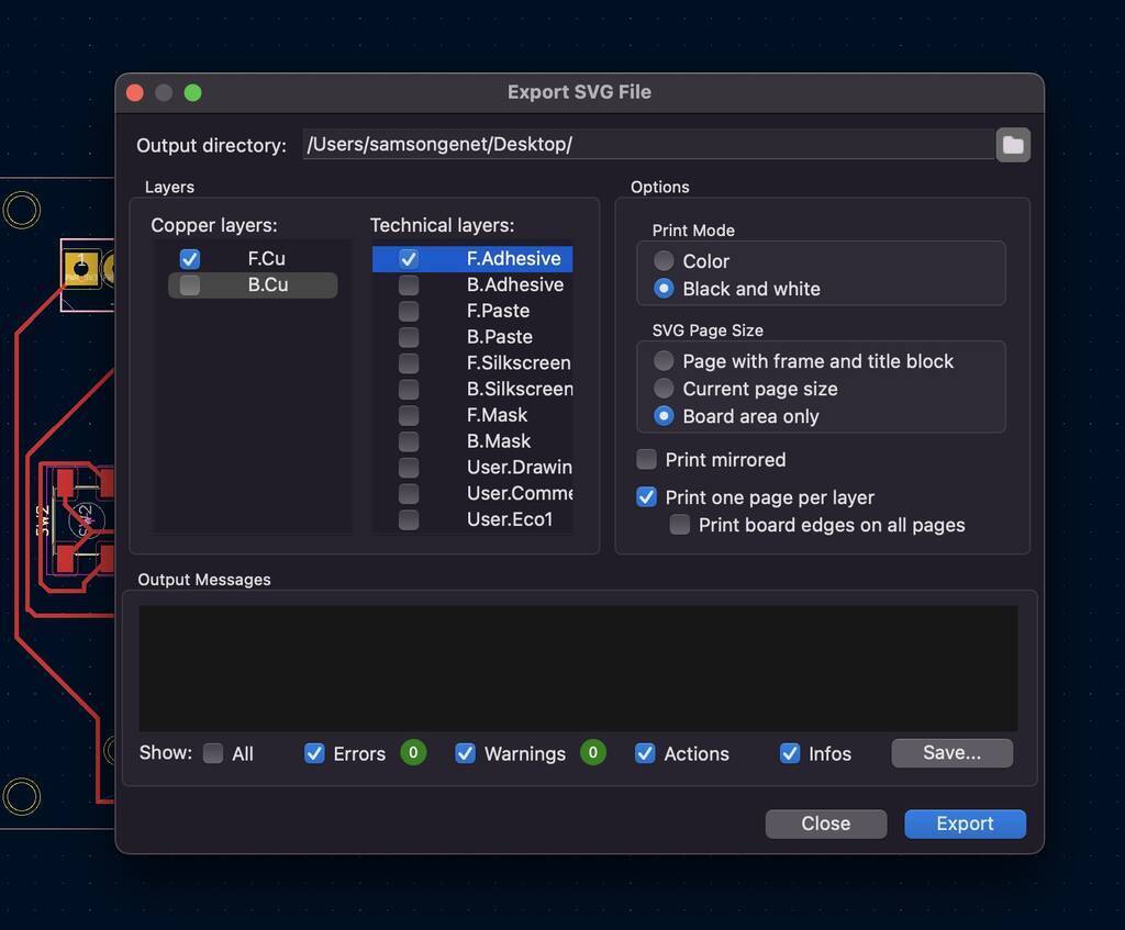
To mill the board we need to export it as a SVG/PNG.
Don’t forget to select the F.Cu for the Copper layer and Edge.Cuts for the Technical layers.
- Choose a Black and white print mode
- Choose Board area only for the page size
- Uncheck Print board edges, otherwise the edge will still be present in the traces file (I did this wrong the first time)
- Uncheck Print mirrored (although I believe it’s unchecked by default)
- Choose One file per layer to make sure that the traces and interior become separate files
I exported the image as a SVG. I need to make extra plates at the vcc and gnd battery connection so my wires will be attached nicely.

I copy paste 2 copper plates for my gnd and vcc. This should work for now.
I want 2 different images to import in MODS. One for my cut outs and one for my traces for soldering.
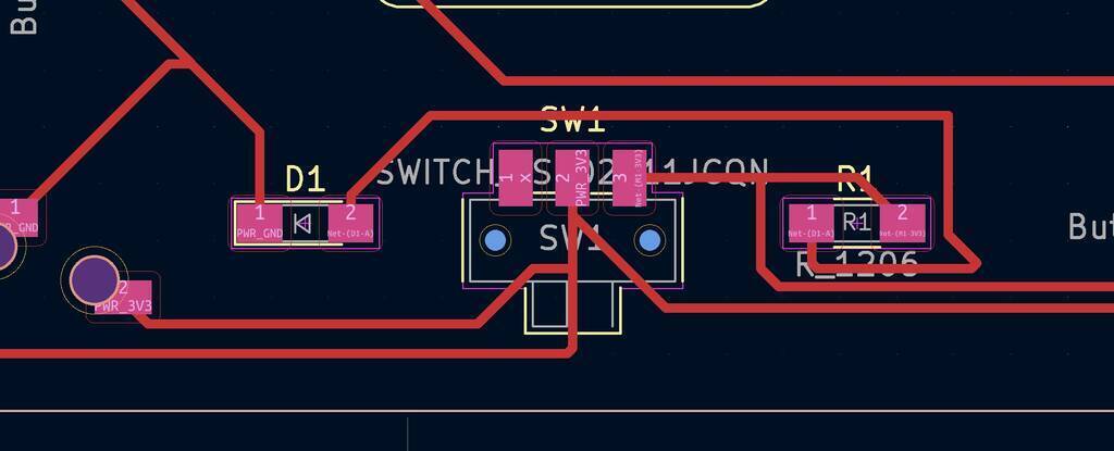
This line should be behind the the switch. Otherwise I power the joystick constantly and will draw my battery empty.
Let’s go again.
I’ve manually added holes in illustrator in the center of the masks. I’m not sure why it didn’t exported correctly. The holes where also way to big. I gave the holes a tollerance an offset of .2 mm.

When I tried to import them in MODS the traces weren’t visible. Illustrator changed my line thickness.... All the changes that I had to make manually I did in Kicad and exported it. Mods can read my files correctly now.
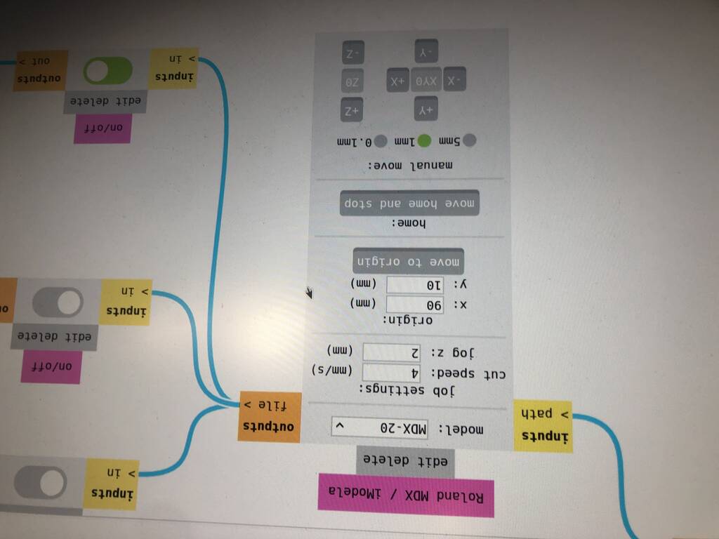
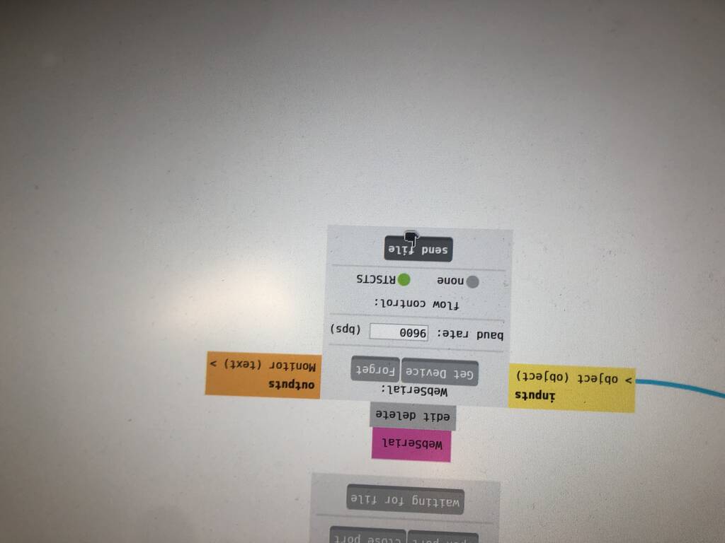
MODS
Select the Roland miller.
Select PNG or SVG. Go for a SVG file if its possible.
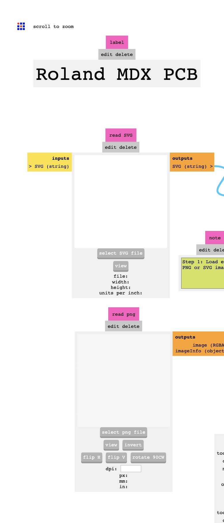
Select mill traces or mill outline
Check the settings. For traces this is fine. For the oultine measure the thickness of your board and add that to the mac depth. Go for a cut depth of .....
Select your wanted position of the mill.
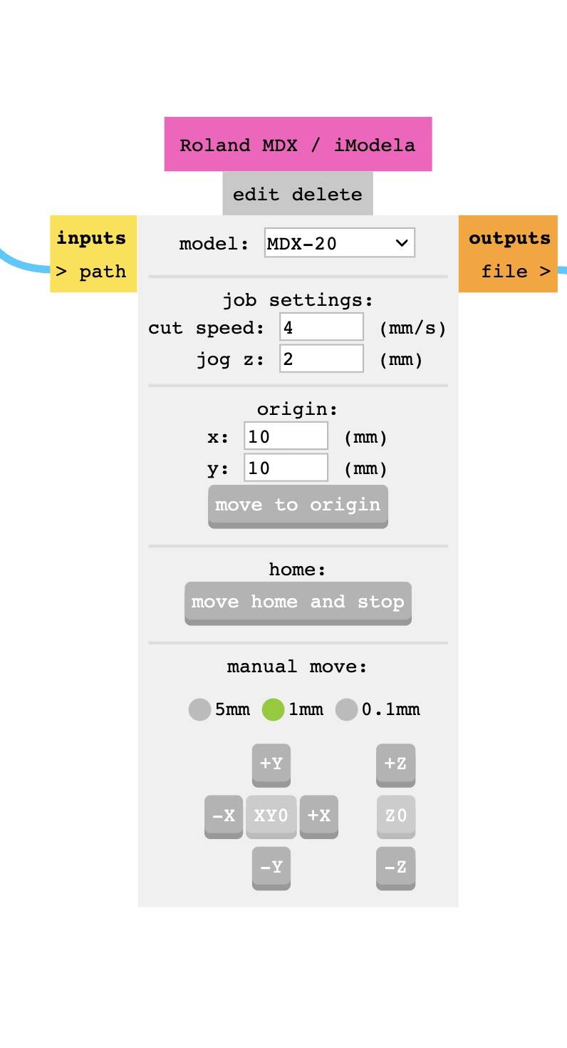
Get device and connect it.
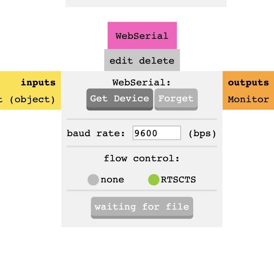
Send file.
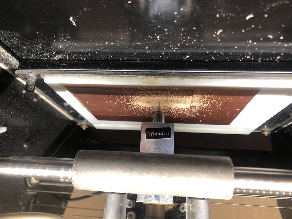
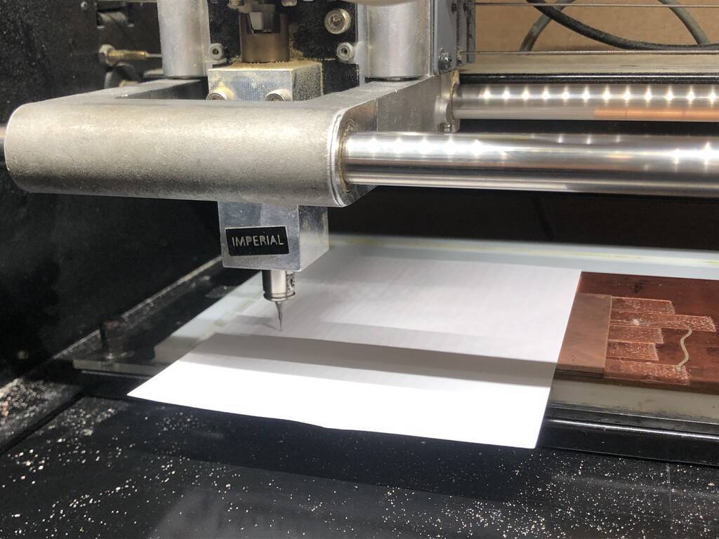
Milling
My board is pretty big so I had to change the top board so my design would fit.
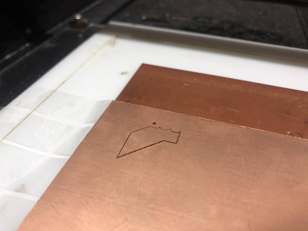
During the milling process I think the end mill broke.
After replacing the end mill and run the design again this was the result.

So what happend?
I did several things incorrect.
- When I changed the board I didn’t measured the thickness in all the corners.
- I didn’t pressed the board up side down to make sure everyting would get pressed down.
- I screwed the screws to thight.
- I didn’t place the board in the correct position.
But most importantly I made a big mistake in my Kicad design.
I selected my outline in User.9. The outline should be in layer margin. Kicad then knows the reference to make the outer traces as well.
Also I selected the holes and the outline in the same layer. This should be in different layers of course.
This should work now.
Ok. Let’s have a fresh start.
1: schematics
2: pcb editor
- outline in margin
- extra cut outs in map 9 e.g.
3: attach new board
- measure with calibrator
- don’t set screws to thight
- level correct. Start in the middle and then go to each corner. Like you do with a 3d printer.
Leveling with paper.
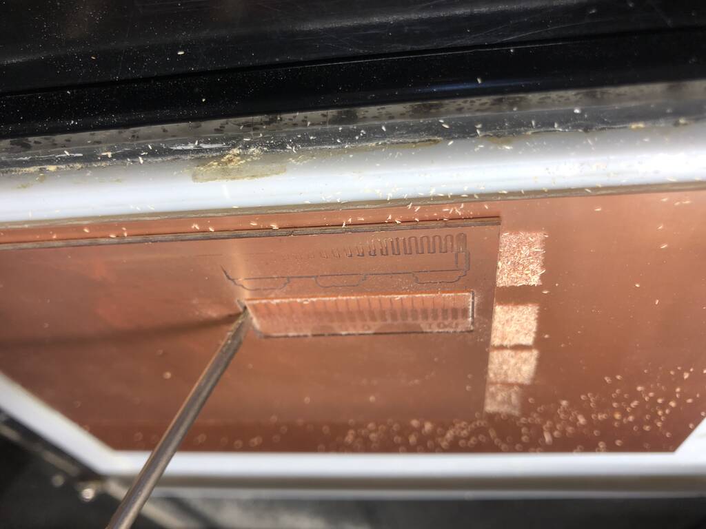
First I forgot to put the drill a tiny bit up before we started to drill. Then you get this result.
Here you see that a small part isn’t milled.
That’s because the distance between these lines is .25. That’s not possible of course with a drill bit of .4 mm.

I neet some through holes in my board. I draw these myseld in kicad. But mods is drilling on the line… You can see that here in this image. I’ll draw a few point not instead of the circles. The holes will probably be to small. But I can drill them out with a hand drill if I need to

I had some problems with the trough holes. I’m not sure why but orientation changed when I imported the points. I tried it out with leveling the Z axes to high and a minimal cut depth.
This is the result. I’ll drill the holes with a regular drill.
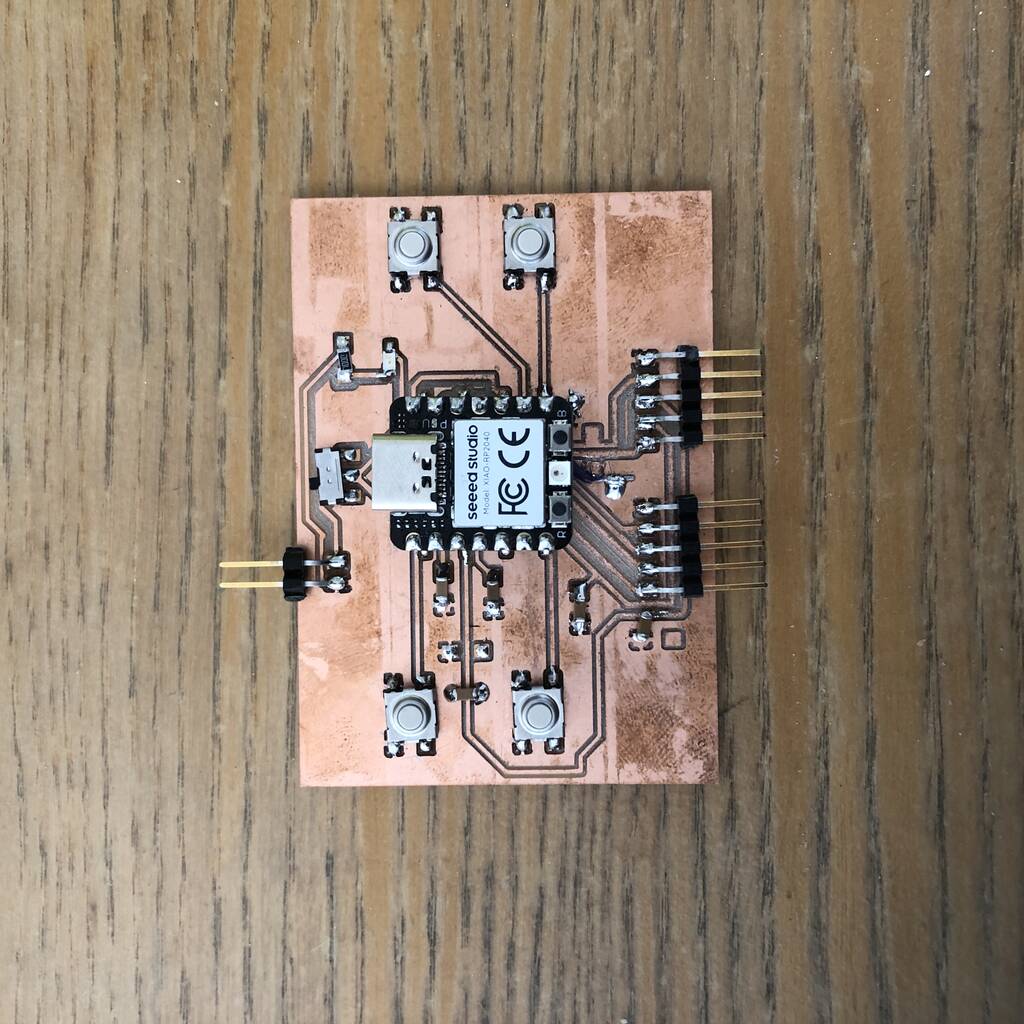
New Controller
After a lot of struggle I decided to make a new controller. See my schematic and pcb drawings below.

The XIAO ESP32C3 is capable of using a 3.7V lithium battery as the power supply input. You can refer to the following diagram for the wiring method.

Which resistor for the LED
LED
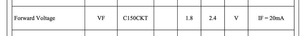
Voltage - Forward (Vf) (Typ) 2.2V
Current - Test 20mA
3.7V to 2.2 V
The forward voltage of a LED is 2.2V (check with the manufacturer). Forward current 20mA, so - using Ohms law, 3.7V battery - 2.2V LED = 1.5V and 1.5/.020 = 75 Ohms.
75ohm resistor
| type | amount | link |
|---|---|---|
| tactile swith | 4 | link |
| Slide switch | 1 | link |
| Led green | 1 | link |
| Resistor 100 ohm | 1 | link |
| 3.7 battery | 1 | link |
| Joysticks | 2 |
Joystick needs 5 volt?
Since I’m using a 3.7 lithium battery. I’ll power the joysticks with 3.3 instead of 5v. Hopefully this won’t give any trouble.
Checked if the buttons work with this code
int pushButton = D6;

void setup() {

Serial.begin(9600);

pinMode(pushButton, INPUT);

}


void loop() {

int buttonState = digitalRead(pushButton);

Serial.println(buttonState);

delay(1);

}
Only 2 buttons worked. I soldered them the wrong way......
Ground poor kicad
The ground poor works super nice and makes drawing traces easier.
Place
add filled zone
select GND
CLick B on the keyboard
everytime you make a new adjustment in the PCB design click B
Servos + esp32-c3
I want to control 4 servos with 1 esp32-c3 xiao board.
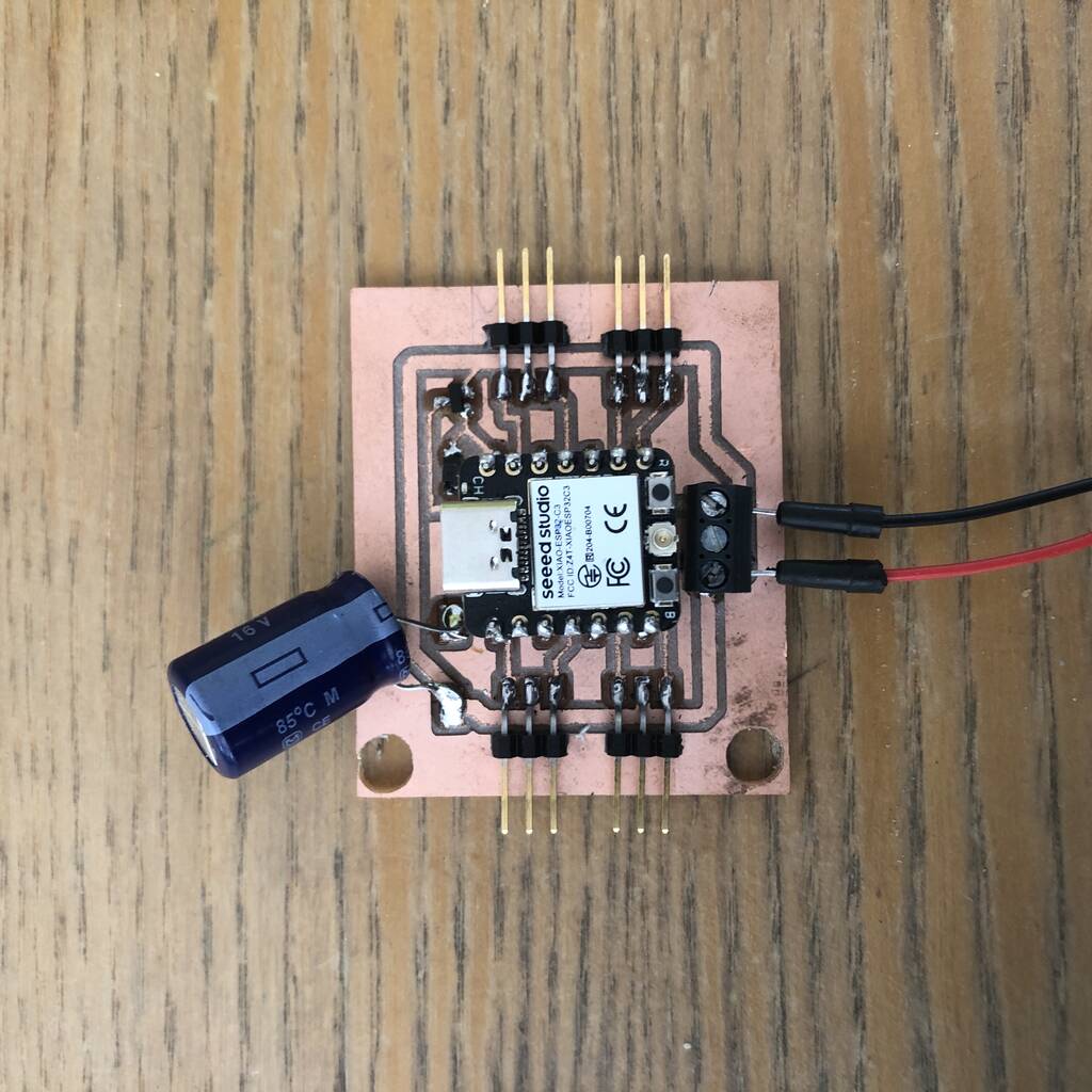
See the schematics and pcb below.
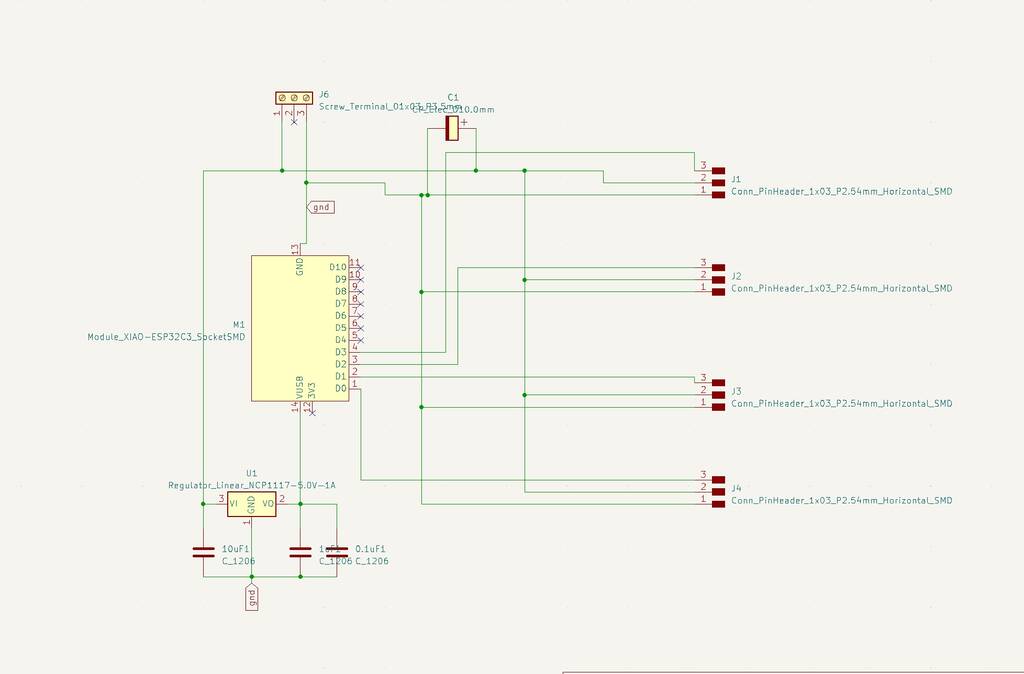

This is the milled board with the soldered components. I used a big capicitor to run the servos smoothly.
It’s a hassle to control 4 servos at the same time with a xiao esp32-c3 board.
With this code I can only control 2 servos at once.
#include <ESP32Servo.h>

Servo myservo1;   // create servo object to control a servo
Servo myservo2;  // twelve servo objects can be created on most boards
Servo myservo3;
Servo myservo4;

int pos = 90;    // variable to store the servo position

// attaches the servo on pins to the servo object
void setup() {
  myservo1.attach (27);
  myservo2.attach (21);
  myservo3.attach (18);
  myservo4.attach (26);

}

void loop() {

  for (pos = 90; pos <= 180; pos += 1) { // goes from 0 degrees to 180 degrees
    // in steps of 1 degree
    myservo1.write(pos);              // tell servo to go to position in variable 'pos'
    delay(15);                       // waits 15ms for the servo to reach the position
  }
  for (pos = 180; pos >= 90; pos -= 1) { // goes from 180 degrees to 0 degrees
    myservo1.write(pos);              // tell servo to go to position in variable 'pos'
    delay(15);                       // waits 15ms for the servo to reach the position
  }


  for (pos = 90; pos <= 180; pos += 1) { // goes from 0 degrees to 180 degrees
    // in steps of 1 degree
    myservo2.write(pos);              // tell servo to go to position in variable 'pos'
    delay(15);                       // waits 15ms for the servo to reach the position
  }
  for (pos = 180; pos >= 90; pos -= 1) { // goes from 180 degrees to 0 degrees
    myservo2.write(pos);              // tell servo to go to position in variable 'pos'
    delay(15);                       // waits 15ms for the servo to reach the position
  }


  for (pos = 90; pos <= 180; pos += 1) { // goes from 0 degrees to 180 degrees
    // in steps of 1 degree
    myservo3.write(pos);              // tell servo to go to position in variable 'pos'
    delay(15);                       // waits 15ms for the servo to reach the position
  }
  for (pos = 180; pos >= 90; pos -= 1) { // goes from 180 degrees to 0 degrees
    myservo3.write(pos);              // tell servo to go to position in variable 'pos'
    delay(15);                       // waits 15ms for the servo to reach the position
  }


  for (pos = 90; pos <= 180; pos += 1) { // goes from 0 degrees to 180 degrees
    // in steps of 1 degree
    myservo4.write(pos);              // tell servo to go to position in variable 'pos'
    delay(15);                       // waits 15ms for the servo to reach the position
  }
  for (pos = 180; pos >= 90; pos -= 1) { // goes from 180 degrees to 0 degrees
    myservo4.write(pos);              // tell servo to go to position in variable 'pos'
    delay(15);                       // waits 15ms for the servo to reach the position
  }

}
I have the following pins connected.
d0
d5
d7
d10
The order is important. If I start with d7 and 10 in my code these to servos work. If I start with d0 and d5 first these servos respond. So my PCB is work fine but de XIAO board is acting weird.
Got al my servos working with an Arduino at the same time! This is good and bad news. My PCB is probably fine but the xiao board is being a fucker because it won’t cooparate.
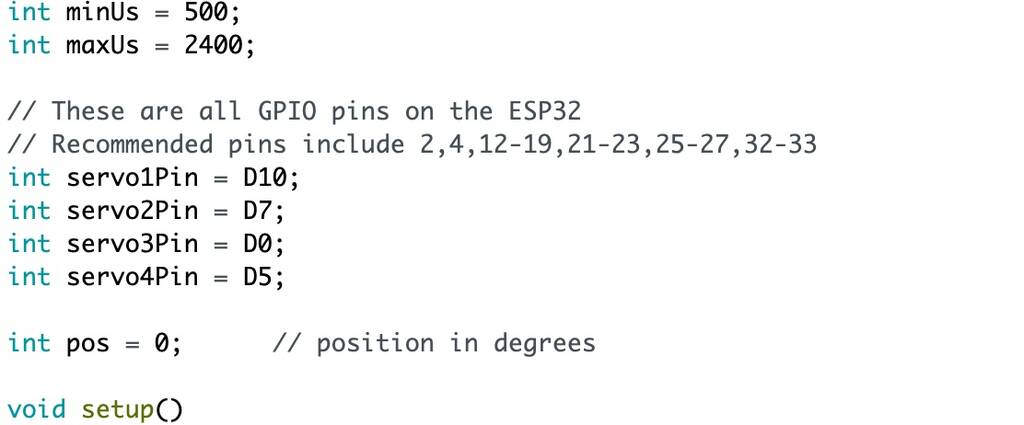
OK! I got it to work now with the following code!
/*
 * ESP32 Servo Example Using Arduino ESP32 Servo Library
 * John K. Bennett
 * March, 2017
 *
 * This sketch uses the Arduino ESP32 Servo Library to sweep 4 servos in sequence.
 *
 * Different servos require different pulse widths to vary servo angle, but the range is
 * an approximately 500-2500 microsecond pulse every 20ms (50Hz). In general, hobbyist servos
 * sweep 180 degrees, so the lowest number in the published range for a particular servo
 * represents an angle of 0 degrees, the middle of the range represents 90 degrees, and the top
 * of the range represents 180 degrees. So for example, if the range is 1000us to 2000us,
 * 1000us would equal an angle of 0, 1500us would equal 90 degrees, and 2000us would equal 1800
 * degrees.
 *
 * Circuit:
 * Servo motors have three wires: power, ground, and signal. The power wire is typically red,
 * the ground wire is typically black or brown, and the signal wire is typically yellow,
 * orange or white. Since the ESP32 can supply limited current at only 3.3V, and servos draw
 * considerable power, we will connect servo power to the VBat pin of the ESP32 (located
 * near the USB connector). THIS IS ONLY APPROPRIATE FOR SMALL SERVOS.
 *
 * We could also connect servo power to a separate external
 * power source (as long as we connect all of the grounds (ESP32, servo, and external power).
 * In this example, we just connect ESP32 ground to servo ground. The servo signal pins
 * connect to any available GPIO pins on the ESP32 (in this example, we use pins
 * 22, 19, 23, & 18).
 *
 * In this example, we assume four Tower Pro SG90 small servos.
 * The published min and max for this servo are 500 and 2400, respectively.
 * These values actually drive the servos a little past 0 and 180, so
 * if you are particular, adjust the min and max values to match your needs.
 * Experimentally, 550 and 2350 are pretty close to 0 and 180.
 */

#include <ESP32Servo.h>

// create four servo objects
Servo servo1;
Servo servo2;
Servo servo3;
Servo servo4;
Servo servo5;
// Published values for SG90 servos; adjust if needed
int minUs = 1000;
int maxUs = 2000;

// These are all GPIO pins on the ESP32
// Recommended pins include 2,4,12-19,21-23,25-27,32-33
// for the ESP32-S2 the GPIO pins are 1-21,26,33-42
// for the ESP32-S3 the GPIO pins are 1-21,35-45,47-48
// for the ESP32-C3 the GPIO pins are 1-10,18-21
#if defined(CONFIG_IDF_TARGET_ESP32C3)
int servo1Pin = D0;      //GPIO2
int servo2Pin = D5;      //GPIO21
int servo3Pin = D7;      //GPIO20
int servo4Pin = D10;     //GPIO9
#endif

int pos = 0;      // position in degrees
ESP32PWM pwm;
void setup() {
    // Allow allocation of all timers
    ESP32PWM::allocateTimer(0);
    ESP32PWM::allocateTimer(1);
    ESP32PWM::allocateTimer(2);
    ESP32PWM::allocateTimer(3);
    Serial.begin(115200);
    servo1.setPeriodHertz(50);      // Standard 50hz servo
    servo2.setPeriodHertz(50);      // Standard 50hz servo
    servo3.setPeriodHertz(330);      // Standard 50hz servo
    servo4.setPeriodHertz(200);      // Standard 50hz servo
    //servo5.setPeriodHertz(50);      // Standard 50hz servo

}

void loop() {
    servo1.attach(servo1Pin, minUs, maxUs);
    servo2.attach(servo2Pin, minUs, maxUs);
#if defined(CONFIG_IDF_TARGET_ESP32S2) || defined(CONFIG_IDF_TARGET_ESP32C3)
    pwm.attachPin(37, 10000);//10khz
#elif defined(CONFIG_IDF_TARGET_ESP32C3)
    pwm.attachPin(7, 10000);//10khz
#else
    pwm.attachPin(27, 10000);//10khz
#endif
    servo3.attach(servo3Pin, minUs, maxUs);
    servo4.attach(servo4Pin, minUs, maxUs);

    //servo5.attach(servo5Pin, minUs, maxUs);


    for (pos = 0; pos <= 180; pos += 1) { // sweep from 0 degrees to 180 degrees
        // in steps of 1 degree
        servo1.write(pos);
        delay(1);             // waits 20ms for the servo to reach the position
    }
    for (pos = 180; pos >= 0; pos -= 1) { // sweep from 180 degrees to 0 degrees
        servo1.write(pos);
        delay(1);
    }

    for (pos = 0; pos <= 180; pos += 1) { // sweep from 0 degrees to 180 degrees
        // in steps of 1 degree
        servo2.write(pos);
        delay(1);             // waits 20ms for the servo to reach the position
    }
    for (pos = 180; pos >= 0; pos -= 1) { // sweep from 180 degrees to 0 degrees
        servo2.write(pos);
        delay(1);
    }

    for (pos = 0; pos <= 180; pos += 1) { // sweep from 0 degrees to 180 degrees
        // in steps of 1 degree
        servo3.write(pos);
        delay(1);             // waits 20ms for the servo to reach the position
    }
    for (pos = 180; pos >= 0; pos -= 1) { // sweep from 180 degrees to 0 degrees
        servo3.write(pos);
        delay(1);
    }

    for (pos = 0; pos <= 180; pos += 1) { // sweep from 0 degrees to 180 degrees
        // in steps of 1 degree
        servo4.write(pos);
        delay(1);             // waits 20ms for the servo to reach the position
    }
    for (pos = 180; pos >= 0; pos -= 1) { // sweep from 180 degrees to 0 degrees
        servo4.write(pos);
        delay(1);
    }
    for (pos = 0; pos <= 180; pos += 1) { // sweep from 0 degrees to 180 degrees
        // in steps of 1 degree
        servo5.write(pos);
        delay(1);             // waits 20ms for the servo to reach the position
    }
    for (pos = 180; pos >= 0; pos -= 1) { // sweep from 180 degrees to 0 degrees
        servo5.write(pos);
        delay(1);
    }
    servo1.detach();
    servo2.detach();;
    servo3.detach();
    servo4.detach();
    pwm.detachPin(27);

    delay(5000);

}
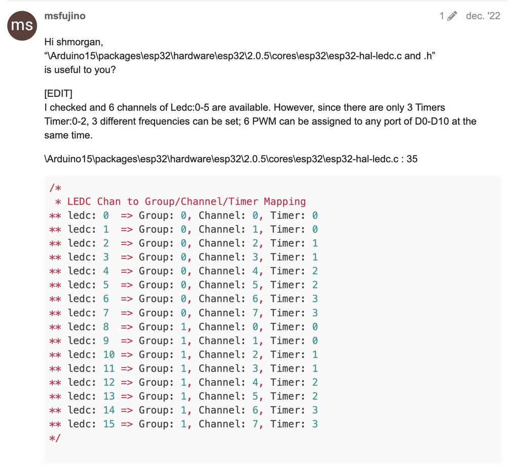
What’s up?
Normaly multiple servos are easy to control. But with the esp32-c3 XIAO seed it’s a hassle. Why?
I got only a few servos working at the same time. This is probably because of a Timer problem in the MCU. See picture below.
Why do we need this ESP32_C3_ISR_Servo library
This library enables you to use 1 Hardware Timer on an ESP32_C3-based board to control up to 16 independent servo motors.
Important Notes about using ISR
Inside the attached function, delay() won’t work and the value returned by millis() will not increment. Serial data received while in the function may be lost. You should declare as volatile any variables that you modify within the attached function.
Typically global variables are used to pass data between an ISR and the main program. To make sure variables shared between an ISR and the main program are updated correctly, declare them as volatile.
Avoid using Serial.print()-related functions inside ISR. Just for temporary debug purpose, but even this also can crash the system any time. Beware.
Your functions are now part of ISR (Interrupt Service Routine), and must be lean / mean, and follow certain rules. More to read on: