9. Output devices
Assignments
Group assignment:
Measure the power consumption of an output device. Document your work on the group work page and reflect on your individual page what you learned.
Individual assignment:
Add an output device to a microcontroller board you’ve designed and program it to do something.
Group assignment
To measure the power consumption we used these two desktop power supplies.
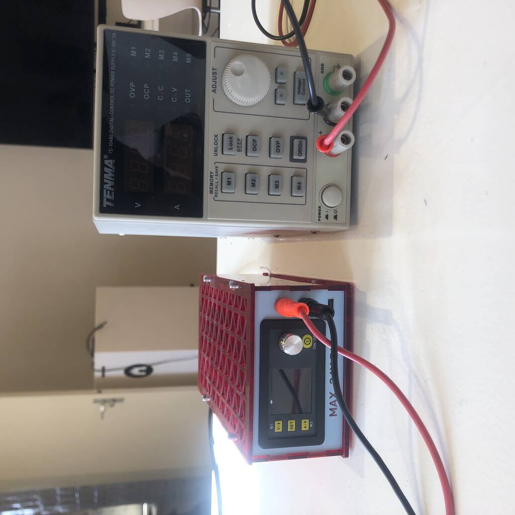
For the group assignment we connected a Nema 17 stepper motor with the MKS TMC2209 V2.0 Stepper Driver and the MG955 stepper motor to an Arduino Uno
Servo’s are relatively easy to connect and to work with. Steppers are a bit tougher because the mechanics is more complex and for that reason not all drivers work with all the stepper motors.
Stepper Nema 17
I think the stepper Nema 17 is one of the most known and used steppers in hobby world now. They are in almost every 3d printer and are relatively easy to work with because of the big ecosystem around those motors.
I’ve worked with the little hobby steppers but never connceted a (serious) steppper motor. To my big surprise it was hard to find information about the MKS TMC2209 V2.0 motor driver. I finally found something via google images, haha.

We connected everything via this link.

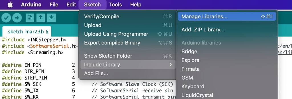
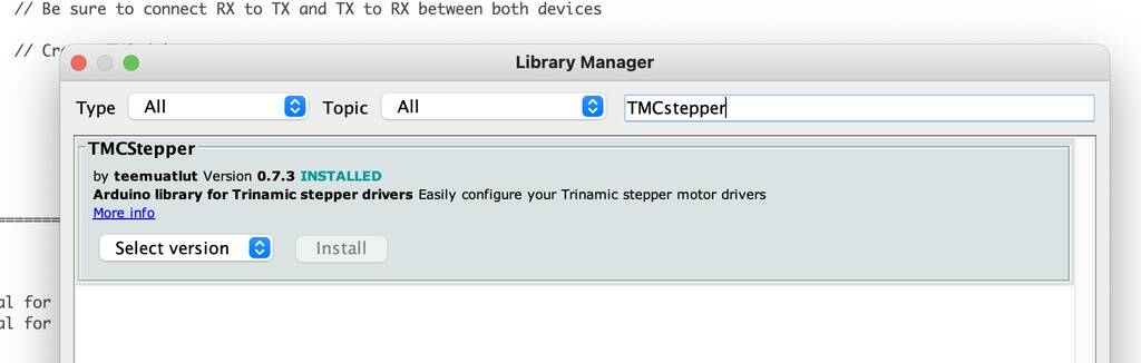
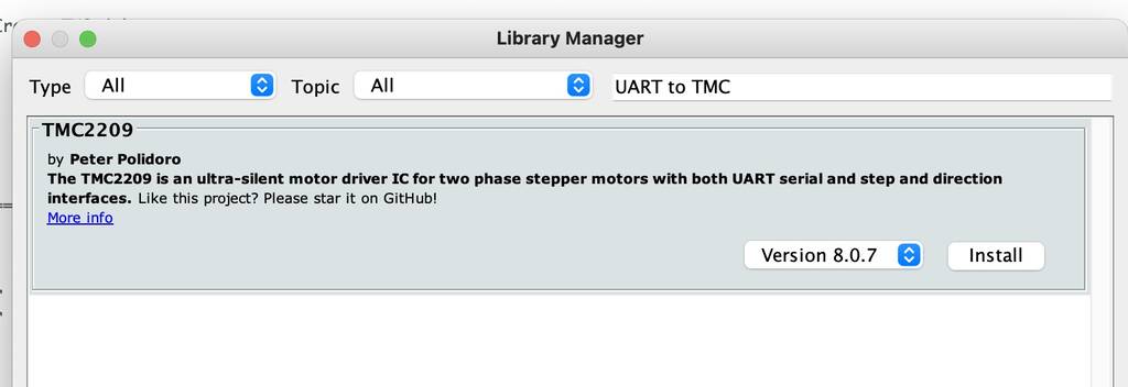
First we installed the TMCstepper and the UART to TMC2209 in the manage library.
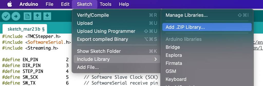
For the serial debugging output you go to this link. Download the latest version and install it via the add ZIP library.
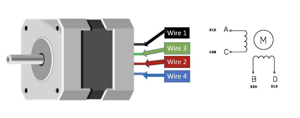
I’m not sure how to wire the Nema 17. I found different options how to wire it. I’m not sure how this works.... I’ll go for this first option
1A - green
1B - black
2A - blue
2B - red
After wiring it up. We tested it. The stepper wasn’t moving. But when you hold thread you could feel a buzz. This means that it was floating, it’s got something to do with the clock function. Not sure how this works.
After connecting the grounds it worked nice. We set the desktop power on 12V and 1A. You could see the voltage drop and the amount of amps the motor would draw.
Servo MG995
For the assignment we wired a MG995 servo motor. These servo’s are pretty easy to wire. We chose to connect it to an external power supply so we could measure the voltage and ampere.
Here you can see that the motor is drawing ca. 80 mA when it’s rotating in it’s normal state. But when we hold it (which was really dificult) the motor almost drew 2A, which is an enormes amount. That’s why these motors are called high torque servo’s. pretty impressive!
#include <TMCStepper.h> // TMCstepper - https://github.com/teemuatlut/TMCStepper
#include <SoftwareSerial.h> // Software serial for the UART to TMC2209 - https://www.arduino.cc/en/Reference/softwareSerial
#include <Streaming.h> // For serial debugging output - https://www.arduino.cc/reference/en/libraries/streaming/
#define EN_PIN 2 // Enable - PURPLE
#define DIR_PIN 3 // Direction - WHITE
#define STEP_PIN 4 // Step - ORANGE
#define SW_SCK 5 // Software Slave Clock (SCK) - BLUE
#define SW_TX 6 // SoftwareSerial receive pin - BROWN
#define SW_RX 7 // SoftwareSerial transmit pin - YELLOW
#define DRIVER_ADDRESS 0b00 // TMC2209 Driver address according to MS1 and MS2
#define R_SENSE 0.11f // SilentStepStick series use 0.11 ...and so does my fysetc TMC2209 (?)
SoftwareSerial SoftSerial(SW_RX, SW_TX); // Be sure to connect RX to TX and TX to RX between both devices
TMC2209Stepper TMCdriver(&SoftSerial, R_SENSE, DRIVER_ADDRESS); // Create TMC driver
int accel;
long maxSpeed;
int speedChangeDelay;
bool dir = false;
//== Setup ===============================================================================
void setup() {
Serial.begin(11520); // initialize hardware serial for debugging
SoftSerial.begin(11520); // initialize software serial for UART motor control
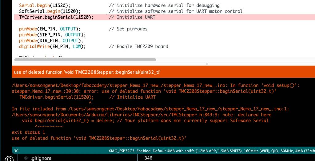
TMCdriver.beginSerial(11520); // Initialize UART
pinMode(EN_PIN, OUTPUT); // Set pinmodes
pinMode(STEP_PIN, OUTPUT);
pinMode(DIR_PIN, OUTPUT);
digitalWrite(EN_PIN, LOW); // Enable TMC2209 board
TMCdriver.begin(); // UART: Init SW UART (if selected) with default 115200 baudrate
TMCdriver.toff(5); // Enables driver in software
TMCdriver.rms_current(500); // Set motor RMS current
TMCdriver.microsteps(256); // Set microsteps
TMCdriver.en_spreadCycle(false);
TMCdriver.pwm_autoscale(true); // Needed for stealthChop
}
//== Loop =================================================================================
void loop() {
accel = 10000; // Speed increase/decrease amount
maxSpeed = 50000; // Maximum speed to be reached
speedChangeDelay = 100; // Delay between speed changes
for (long i = 0; i <= maxSpeed; i = i + accel){ // Speed up to maxSpeed
TMCdriver.VACTUAL(i); // Set motor speed
Serial << TMCdriver.VACTUAL() << endl;
delay(100);
}
for (long i = maxSpeed; i >=0; i = i - accel){ // Decrease speed to zero
TMCdriver.VACTUAL(i);
Serial << TMCdriver.VACTUAL() << endl;
delay(100);
}
dir = !dir; // REVERSE DIRECTION
TMCdriver.shaft(dir); // SET DIRECTION
}
Stepper Nema 17
I want to make a PCB for:
- (Stepper nema 17)[9https://www.pololu.com/file/0J714/SY42STH38-1684A.pdf]
- TMC2209 V2.0 MKS stepper driver
- module Xiao esp32-C3 socket smd
- 2 x - pth 8 pins for driver
Let’s start with a schematic. I could’t find the library for the TMC2209 V2.0 MKS stepper driver. So I decided to go for a view smd pin connectors.
It was hard to find something similar so I used this wiring (diagram). It’s not perfect but during the group assignment it proved it worked.

I turned my driver up side down so you see it’s the same.
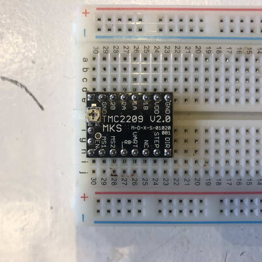
Here you see the pins that I’ll use from de stepper driver.

Existing wiring.
This is the wiring from the driver to the arduino. Since I’ll use an ESP32 I’ll check what type of pins these are so I know what to do with the ESP.
Arduino Uno wiring TMC2209 V2.0
Pin 2 = EN (Enable) -> digital
Pin 7 = TX (transmittor) -> digital tx pin
Pin 6 = RX (receiver) -> digital rx pin
Pin 5 = NC ClK (clock) -> digital pin
Pin 4 = STEP (steps) -> digital pin
Pin 3 = DIR (direction) -> digital pin
Arduino uno Pin layout
| Pin number | Pin name | description | Alternative functions |
|---|---|---|---|
| Pin 2 | TX/D1 | Digital IO Pin 1 / Serial TX Pin | Generally used as TX |
| Pin 7 | D6 | Digital IO Pin 6 | |
| Pin 6 | D5 | Digital IO Pin 5 | Timer (OC0B/T1) |
| Pin 5 | D4 | Digital IO Pin 4 | Timer (T0/XCK) |
| Pin 4 | D3 | Digital IO Pin 3 | Timer (OC2B) |
| Pin 3 | D2 | Digital IO Pin 2 |
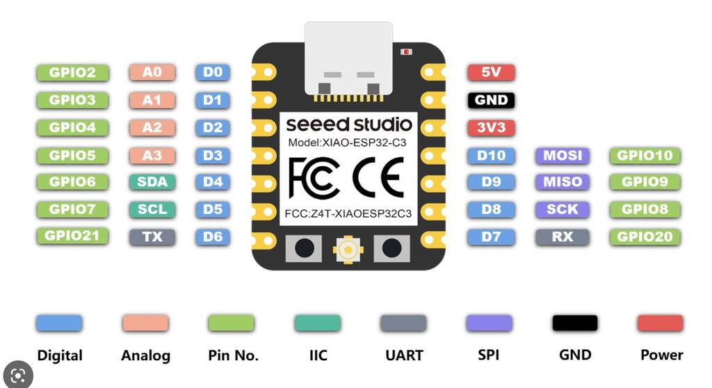
New wiring
ESP 32-c3 Xiao wiring TMC2209 V2.0

| Pin number ESP | TMC2209 V2.0 |
|---|---|
| D0 | EN |
| D6 (TX) | RX (code sais I tx with rx and vica versa) |
| D7 (RX) | TX (code sais I tx with rx and vica versa) |
| D1 | NC / CLK |
| D2 | STEP |
| D3 | DIR |
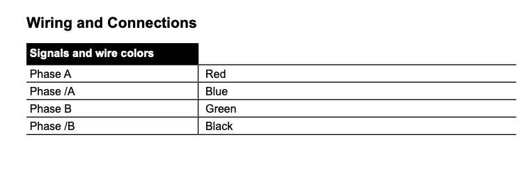
TMC2209 V2.0 wiring Nema 17
| Coils | Pins |
|---|---|
| Black | 1B |
| Green | 1A |
| Red | 2A |
| Blue | 2B |
Code in Arduino ID
I used a code and followed the wiring directions.
SoftwareSerial SoftSerial(SW_RX, SW_TX); // Be sure to connect RX to TX and TX to RX between both devices
I defined my new Pin layout
Let’s try it out. I get the following error when compiling

I though I did this…

Let’s try this out
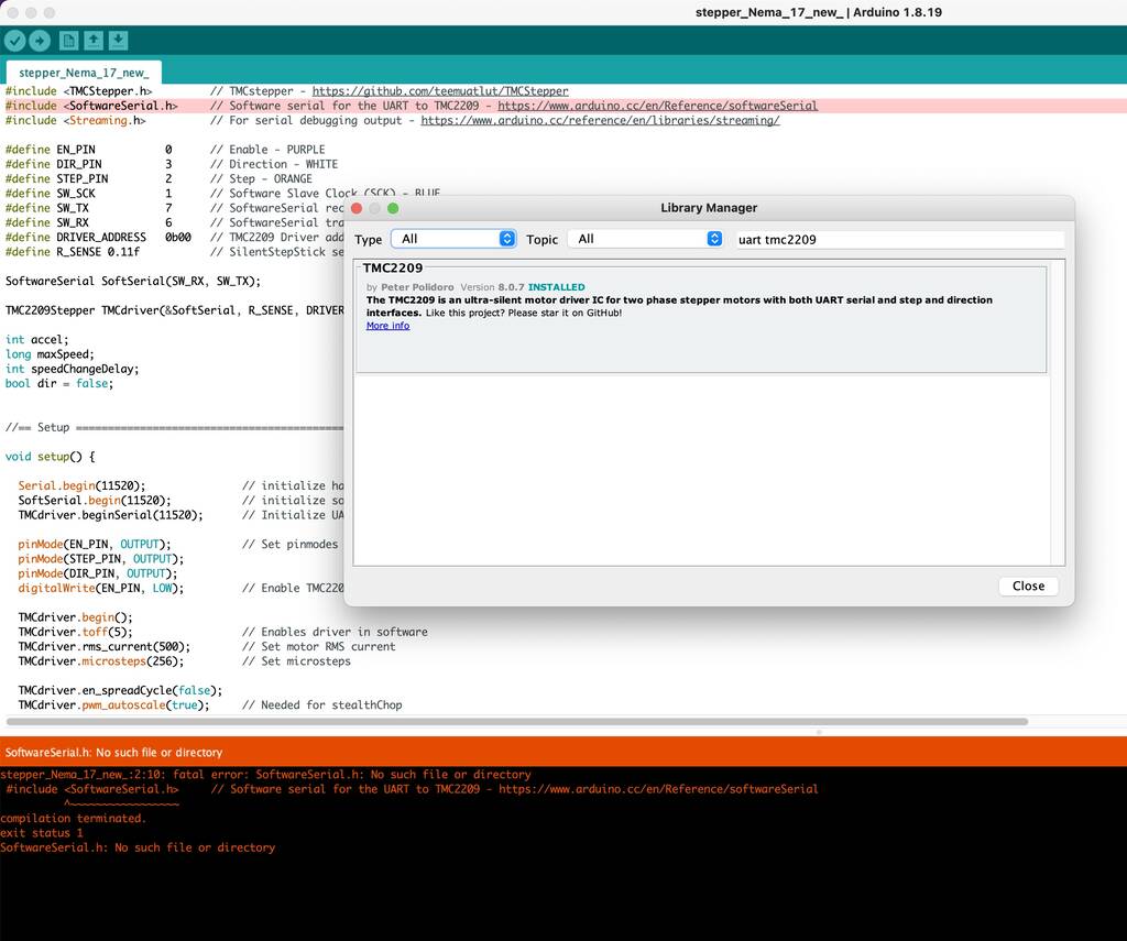
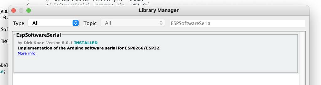
Still not working. Someone on the world wide web said this: The ESP32 doesn’t have a softwareserial library, so you need to download the library “ESPSoftwareSerial” from the library manager, and then It should be ok.
Let’s try that out.
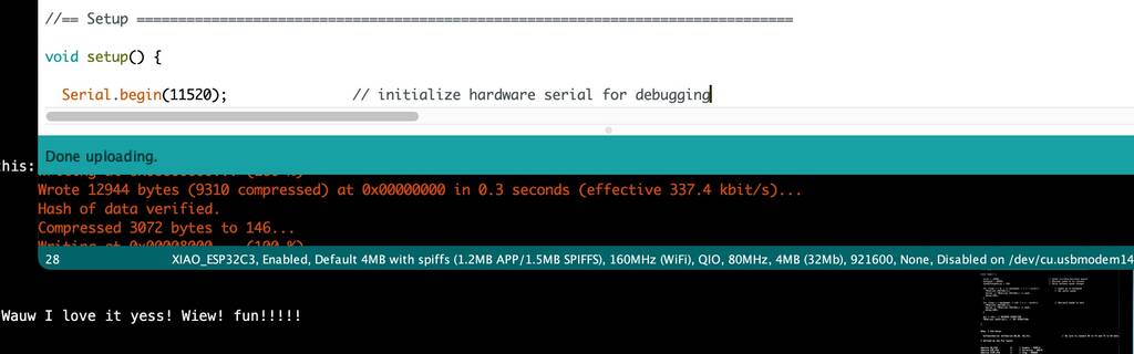
Yes! It worked and now a new problem emerged! So cool! Wauw I love it yess! Wiew! fun!!!!!
I’ve used a different code now and I get kind of the same error. It’s got something to do with my serial port.
I’m not sure what I’ve done. But my file is uploaded now. No idea why. But my stepper motor isn’t working.
Conclusion
It didn’t work out. Why? It got something to do with my the UART connection. I think it’s not neccesary to connect the RX and the TX. Also I don’t like to work with a driver that has few information to find due to the connection with my MU of choise. Since my struggle took a while I decided to try it with an other driver that I bought a while back.
Stepper Nema 17 Vol.2
Since the previous attemt didn’t work out and I got frustrated I wanted to try it out with a different stepper driver that I bought some time ago. This driver is way more popular and there’s a lot of stuff to find that can help me out.
Components
- Stepper Nema 17 datasheet
- A4988
- Esp32-C3
To make my life a bit easier I decided to work with an example that will guide my way through the process… This link helped me out big time.
Nema 17
Specifications
- Its rated voltage is 12V
- Phase current is 2.2A
- The Holding torque is equal to 40N.cm
- One step angle will be of 1.8 Deg.
- Total steps for each resolution will be 200.
- 4-wire and 8-inch lead
- Number of phases are 4
- Total inductance by each phase will be 2.8 mH
- The resistance of the coil is 1.5 Ohm per coil
A4988 Driver Module
The A4988 Driver Module is used to control the speed and direction of stepper motors mainly used in robotics, toys, 3D printers for motion control. It is capable of operating bipolar stepper motors in full step, half step, quarter step, eighth step, and sixteenth step modes. There is a built in translator which allows only two pins from the ESP32 board to be used to control the speed and direction of the stepper motor.
Specifications
- Maximum Operating Voltage: 35V
- Minimum Operating Voltage: 8V
- Maximum Current per phase is 2A so it can easily control NEMA17 that has an output current of 2A per phase.
- Dimensions: 15.5 × 20.5 mm (0.6″ × 0.8″)
- Capable of operating bipolar stepper motors in full step, half step, quarter step, eighth step, and sixteenth step modes
- In full step, the driver has 200 steps per revolution which is 1.8 degrees per step.
- Has thermal shutdown circuitry
The A4988 Driver Module as comes with a heat sink to cool the inner circuity in case of higher power dissipation. It allows the IC to cool down if temperatures go higher than safe ones. Thus, if you not attaching the heat sink then the driver module will allow 1A current per phase. However, with cooling feature the maximum allowed current per phase will be 2A instead. So it is always advisable to use the heatsink.
Pin layout
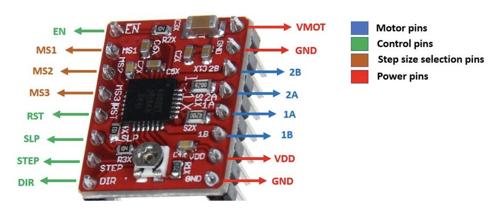
The module has a total of 16 pins which can be divided in four categories: the output pins in blue which will be connected with the motor, the control pins in green, the step size selection pins in brown and the power pins in red.
Let us discuss them one by one.
Motor Pins
These are the motor coil pins connected to each of the four coils of the motor. These pins will be connected with bipolar stepper motors (8V-35V) where output maximum current is 2A per coil. Hence each pin will be able to supply max 2A to each of the coil of the stepper motor.
2B: This is connected with motor coil 2 second pin. 2A: This is connected with motor coil 1 second pin. 1A: This is connected with motor coil 1 first pin. 1B: This is connected with motor coil 2 first pin.
Control Pins
STEP: This is the pin which controls the rotation steps (microsteps) of the motor. It will be connected with a GPIO pin of ESP32. When a high signal will be passed to this pin, the motor will move by one step. The speed of the motor rotation will change according to how soon the signal of the pin goes high.
DIR: This is the pin which controls the direction of the rotation of the motor. This will also be connected to a GPIO pin of ESP32. When a high signal is passed to this pin, the motor will rotate clockwise whereas if a low signal is provided instead, the motor will rotate in an anti-clockwise direction.
EN: This is the enable pin. It is used turn the outputs of the module on or off. A high signal will disable the outputs. By default the pin is at a low state.
RST: This is the reset pin. It sets the internal translator to a predefined Home state which is the position where the motor starts initially. This position will vary depending upon the microstep resolution. This is an active low input where a HIGH signal will enable the driver.
SLP: This is also an active low input pin which is used to reduce power consumption by setting the module to sleep mode when the motors are not in use. This is achieved by supplying a low signal to this pin.
Wiring
Connect the output pins of the driver with the respective motor pins. Connect the STEP pin and the DIR pin with any appropriate GPIO pin of ESP32 board. We have used GPIO12 to connect with DIR and GPIO14 to connect with STEP. As we want to operate our stepper mode in full mode hence we will leave the MS1, MS2 and MS3 pins as they are. The RST pin will be connected with SLP so that the driver is enabled. Moreover, the VCC and GND pins will be connected with Vin and GND pin from ESP32 respectively. The VMOT will be connected with an external power supply ranging between 8-35V. We are using 12V external power supply. Make sure the GND pins are connected with the respective common grounds.
Any GPIO will do for the STEP and DIR
2B: This is connected with motor coil 2 second pin.
2A: This is connected with motor coil 1 second pin.
1A: This is connected with motor coil 1 first pin.
1B: This is connected with motor coil 2 first pin.

Additionally, we can also add a capacitor(minimum 47uF) with the external power supply connected with the stepper motor power supply pins to avoid voltage spike issues.
Current limitor
Before connecting the stepper motor with the driver module we have to make sure that the current running through the motor coils does not exceed the maximum rated current of the motor. To do that we will use the current limiting potentiometer featured on the A4988 motor driver as seen below:
A4988 Driver Module Potentiometer
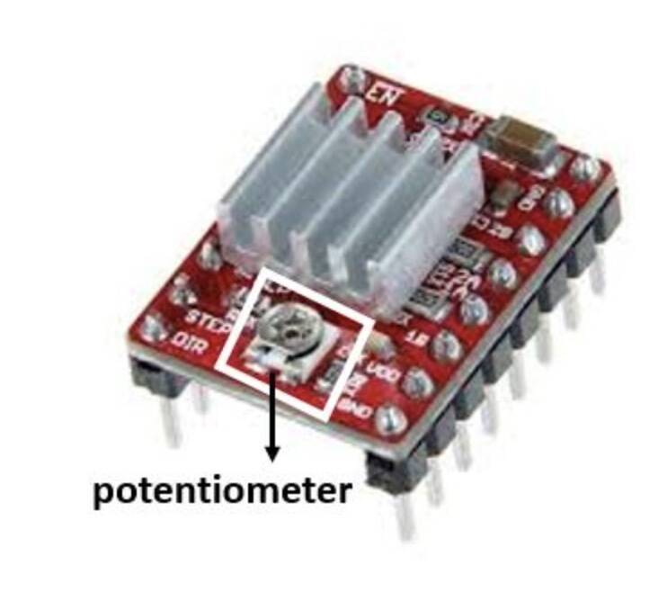
We will require a multimeter. Connect the positive terminal of the multimeter with the potentiometer and the negative end of the mutimeter with the GND of the driver module. The voltage measured at this point will be known as Vref. Adjust the potentiometer by turning it and the values for Vref will vary.
To set a current limit the following formula is used:
Current Limit = Vref x 2.5
Now set the Vref according to your motor’s rated current in order to ensure that the current is within the current limits of the motor.
I measured ca. 0,4V.
0.4 * 2.5 = 1. The current limit is 1 A that should be more then enough to rotate the stepper motor.
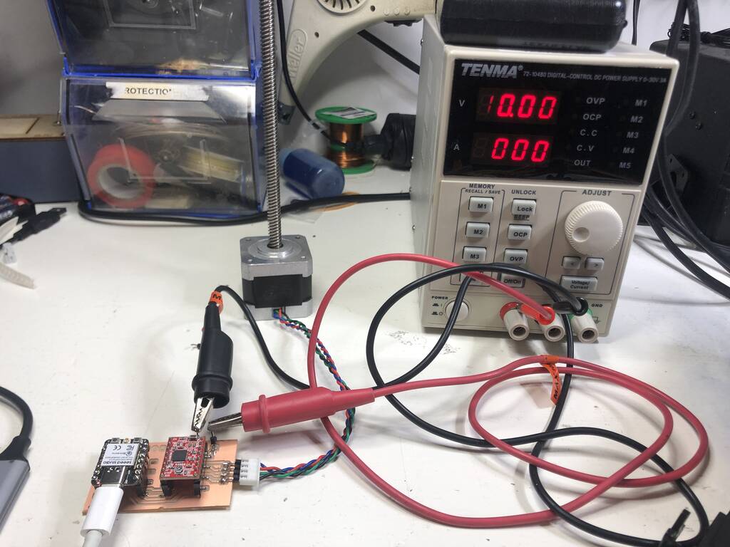
First try
After connecting my 10V 1A power supply to my d0 pin of my ESP so I had to replace my fried MU and driver it worked. But, the motor was vibrating and this shouldn’t be the case. First I thought that the common grounds where not shared. But I think this is internaly set in de driver. I tried it anyway and this didn’t work. Maybe the coils are not connected to the right pins. Lets check that out.
This was my first code:
const int dirPin = 0;
const int stepPin = 1;
const int stepsPerRevolution = 200;

void setup()
{
  // Declare pins as Outputs
  pinMode(stepPin, OUTPUT);
  pinMode(dirPin, OUTPUT);
}
void loop()
{
  // Set motor direction clockwise
  digitalWrite(dirPin, HIGH);

  // Spin motor slowly
  for(int x = 0; x < stepsPerRevolution; x++)
  {
    digitalWrite(stepPin, HIGH);
    delayMicroseconds(2000);
    digitalWrite(stepPin, LOW);
    delayMicroseconds(2000);
  }
  delay(1000); // Wait a second

  // Set motor direction counterclockwise
  digitalWrite(dirPin, LOW);

  // Spin motor quickly
  for(int x = 0; x < stepsPerRevolution; x++)
  {
    digitalWrite(stepPin, HIGH);
    delayMicroseconds(1000);
    digitalWrite(stepPin, LOW);
    delayMicroseconds(1000);
  }
  delay(1000); // Wait a second
}
I switched all the wires without succes. I replaced the motor without succes. I’ll take a look into a new code.
I’ve uploaded the following code but the motor is still vibrating.
const int DIR = 0;
const int STEP = 1;
const int  steps_per_rev = 200;

void setup()
{
  Serial.begin(115200);
  pinMode(STEP, OUTPUT);
  pinMode(DIR, OUTPUT);
}
void loop()
{
  digitalWrite(DIR, HIGH);
  Serial.println("Spinning Clockwise...");

  for(int i = 0; i<steps_per_rev; i++)
  {
    digitalWrite(STEP, HIGH);
    delayMicroseconds(2000);
    digitalWrite(STEP, LOW);
    delayMicroseconds(2000);
  }
  delay(1000);

  digitalWrite(DIR, LOW);
  Serial.println("Spinning Anti-Clockwise...");

  for(int i = 0; i<steps_per_rev; i++)
  {
    digitalWrite(STEP, HIGH);
    delayMicroseconds(1000);
    digitalWrite(STEP, LOW);
    delayMicroseconds(1000);
  }
  delay(1000);
}
Eventually I uploaded the following code and this was working perfectly.
What was the difference? I included the AccelStepper library and the speed of the stepper motor was way faster.
This Accelstepper library supports acceleration and deceleration.
#include <AccelStepper.h>

// Define stepper motor connections and motor interface type. Motor interface type must be set to 1 when using a driver:
#define dirPin 2
#define stepPin 3
#define motorInterfaceType 1

// Create a new instance of the AccelStepper class:
AccelStepper stepper = AccelStepper(motorInterfaceType, stepPin, dirPin);

void setup() {
  // Set the maximum speed in steps per second:
  stepper.setMaxSpeed(1000);
}

void loop()
{
  // Set the current position to 0:
  stepper.setCurrentPosition(0);

  // Run the motor forward at 200 steps/second until the motor reaches 400 steps (2 revolutions):
  while(stepper.currentPosition() != 400)
  {
    stepper.setSpeed(200);
    stepper.runSpeed();
  }

  delay(1000);

  // Reset the position to 0:
  stepper.setCurrentPosition(0);

  // Run the motor backwards at 600 steps/second until the motor reaches -200 steps (1 revolution):
  while(stepper.currentPosition() != -200)
  {
    stepper.setSpeed(-600);
    stepper.runSpeed();
  }

  delay(1000);

  // Reset the position to 0:
  stepper.setCurrentPosition(0);

  // Run the motor forward at 400 steps/second until the motor reaches 600 steps (3 revolutions):
  while(stepper.currentPosition() != 600)
  {
    stepper.setSpeed(400);
    stepper.runSpeed();
  }

  delay(3000);
}
After adjusting the setspeed to 20 steps per second the motor was behaving the same as the previous code. It was moving with clear steps and it wasn’t smooth at all.
Potentiometer
I wanted to control the stepper with a potentiometer. I connected the potentiometer to the 5v output of the ESP, the GND and d2 pin, which is a Analog pin. I’ve uploaded the folowing code. The behaviour was weird and it didn’t work.. I’ll take a look in this when I have more time, I have other priorities.
PCB
It will be a fairly simple board and since I don’t have all the component that I need and struggle a bit with my KiCad design I decided to take a risk and do play fully by the rules. I miss a lot of thing that KiCad wants to know.. Where to power comes from, what kind of pins I use, etc. But I think I’m save.

I drew some solder plates myself and added some holes in my margin folder so I can solder pinholders for my external powersupply and wires from my stepper.
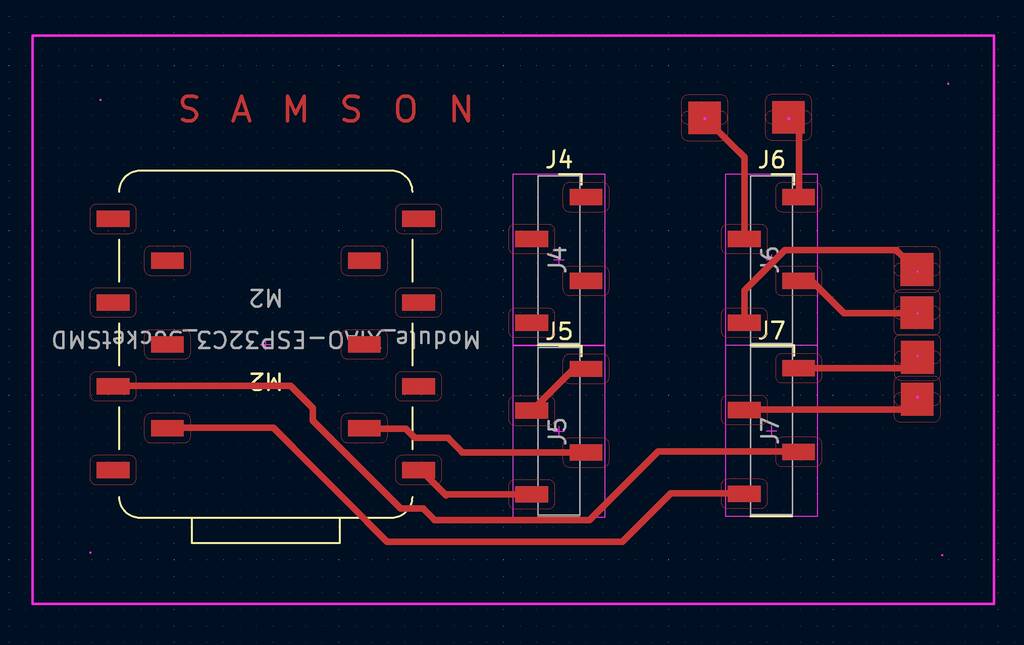
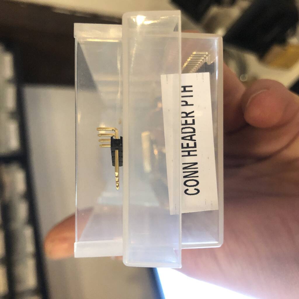
I used these con header pins to attach the stepper motor.
After a lot of struggling (again) with the milling machine it worked out. I had a levelnig problem and it finally worked after replacing the bit for a Vbit. My ideas with the holes didn’t work out so I need to take a look into that later on.

After soldering my componenets for my MU and driver I pulled all the traces lose. Probably because the were to crooked.
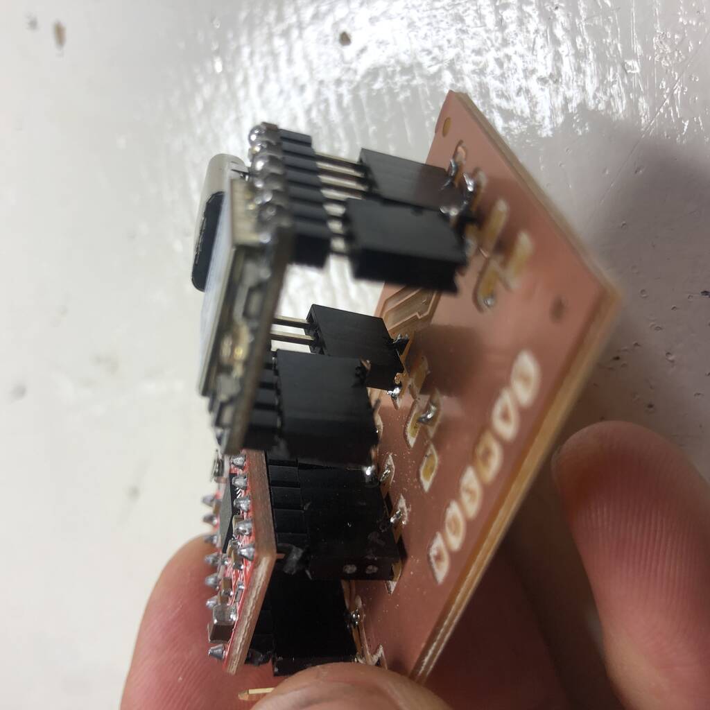
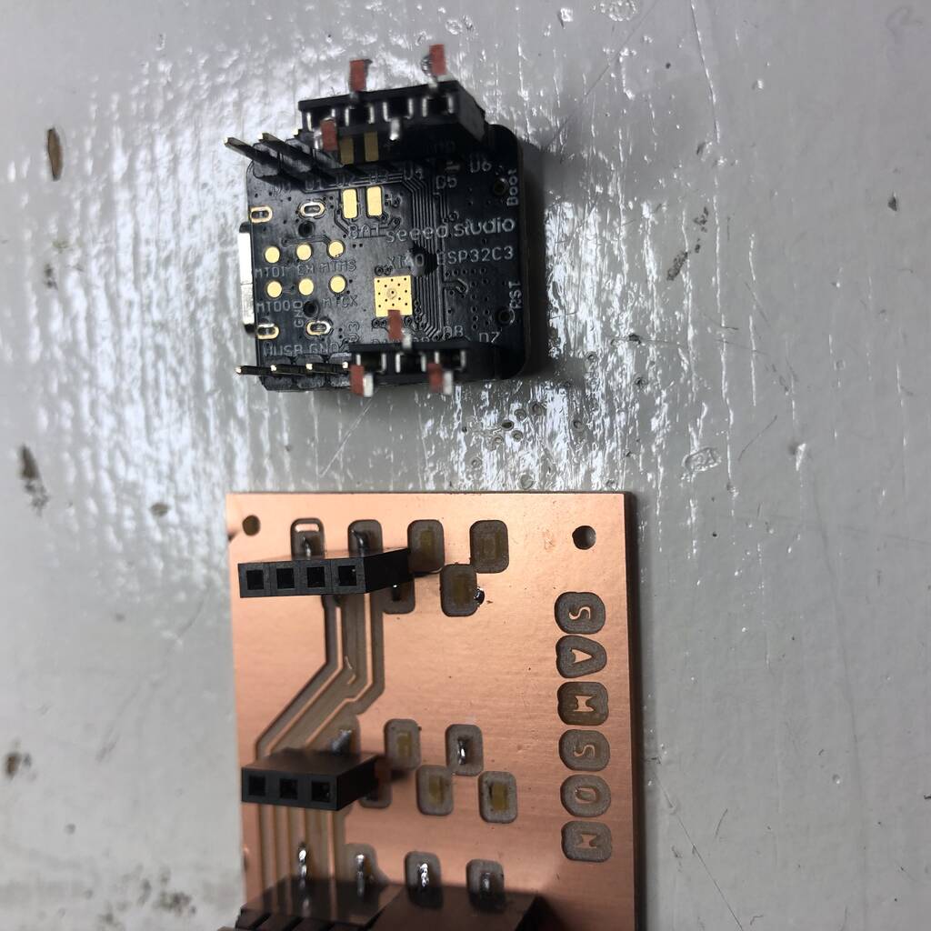
It didn’t work as expected. Also the pins for my external power supply are not the most proffesional solution.
Files
Notes on servo and joysticks
2x Servo MG996R and 2x joysticks
Specifications
• Weight: 55 g
• Dimension: 40.7 x 19.7 x 42.9 mm approx.
• Stall torque: 9.4 kgf·cm (4.8 V ), 11 kgf·cm (6 V)
• Operating speed: 0.17 s/60º (4.8 V), 0.14 s/60º (6 V)
• Operating voltage: 4.8 V a 7.2 V
• Running Current 500 mA
• Stall Current 2.5 A (6V)
• Dead band width: 5 µs
• Stable and shock proof double ball bearing design
• Temperature range: 0 ºC
– 4.8 V a 7.2 V
– 900 mA (6V)
External powersupply 5V 20A
Not sure why but I’m measuring 12 V with this power supply..???? I need max 7.2 V for my servo’s. Maybe I destroyed my multimeter, I have made somem mistakes in the past few months.

(Joystick)[https://components101.com/modules/joystick-module]
| Pin | Pin name | Description |
|---|---|---|
| 1 | GND | Ground terminal of Module |
| 2 | 5V | Positive supply terminal of Module |
| 3 | VRX | Voltage Proportional to X axis |
| 4 | VRY | Voltage Proportional to Y axis |
| 5 | SW | SWITCH |
Technical Specifications
- Operating Voltage: 5V
- Internal Potentiometer value: 10k
- 2.54mm pin interface leads
- Dimensions: 1.57 in x 1.02 in x 1.26 in (4.0 cm x 2.6 cm x 3.2 cm)
- Operating temperature: 0 to 70 °C
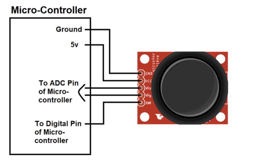
We can use a Joystick Module with Arduino, Raspberry Pi and any other Micro-controllers. We just have to connect the axis Pins VRx and VRy to the ADC Pins of the micro-controller. If you want to use the switch then connect it to the digital Pin of the Micro-controller. Follow the below block diagram to connect Joystick Module with Microcontroller.
What are ADC pins?
An Analog to Digital Converter (ADC) is a very useful feature that converts an analog voltage on a pin to a digital number. By converting from the analog world to the digital world, we can begin to use electronics to interface to the analog world around us.
Wiring
| joytick 1 | joystick 2 | servo 1 | servo 2 | esp |
|---|---|---|---|---|
| gnd | gnd | gnd | gnd | gnd |
| 5v | 5v | vcc | ||
| vrx | d0 | |||
| vry | d1 | |||
| vrx | d2 | |||
| vry | d3 | |||
| sw | d4 | |||
| sw | d5 | |||
| 6v | ||||
| 6v | ||||
| pwm | d6 | |||
| pwm | d7 |
I’ll start with one joystick and two servo’s. See the code below.
code
#include <Servo.h>

Servo servo1;
Servo servo2;

int joyX = 0;
int joyY = 1;
int joyVal;
int dit = 50;

void setup() {
  // put your setup code here, to run once:
servo1.attach(6);
servo2.attach(7);

}

void loop() {
  // put your main code here, to run repeatedly:
joyVal = analogRead(joyX);
joyVal = map (joyVal, 0, 1023, 0, 180);
servo1.write(joyVal);

joyVal = analogRead (joyY);
joyVal = map (joyVal, 0, 1023, 0, 180);
servo2.write (joyVal);
delay(dit);
}
Oops, I got an error. I need to download the esp32servo library.
