18. Project Development
Learning outcomes
Implement project plan Apply time management techniques Summarise and communicate the essence of your project development
Have you answered these questions?
what tasks have been completed? what tasks remain? what has worked? what hasn’t? what questions need to be resolved? what will happen when? what have you learned?
Project Plan
Fab acadamy has been a wild track. Every week we studied a new theme. The last view weeks I’ve been working on different projects that I want to inplement in my final project Octo. How do we keep things organised? In the lectures and in class at the Waag we’ve been talking a lot about spiral development. In the project planning we subdevide our projects in spirals and in chronological order.
Spirals
The idea is to make a modular controlable octopus arm on a linear axes with an inflatable gripper. Below I subdevided the project into different spirals and placed them in chronological order.
The electronical part is the most inportant but also dangerous to loose track of time. I’ve spend days debugging while expecting it was an hour work. It’s inportant to start with the minimal, get 4 servos to work and then continue with the next spiral.
Octo exist out of a lot different parts. To get Octo where I want it to be I have to do a lot of experimenting. This is the main reason I want Octo to be as modular as possible. I want every part to be easy to disassemble in this way I can innovate certain part relatively easy without having to diassemble the model in total. For my next spiral I want to print and redesign the X/Y linear axes form Quinten. This is the phicical foundtation of octo.
Next I’ll make the servo housing. This is the part that I’ll attach to the linear axes and assemble the servos in. Also I need to think how I can attach the first disc to the servo housing so I can attach the vertabrea to it.
The pulleys are relatively easy to make because I already made some prototypes. But I shouldn’t underestimate the choice of using different thread then before. I’ll use fishing thread instead of PA thread. The fishing thread is super thin and smooth. It might slip through the cable clamps.
The tentacle is the easiest to make but it takes a lot of time. I already made a view prototypes and I designed the discs parametric so it’s really easy to make changes when I need to.
During the lectures and in class, assembling is seen as the a underestimated part in the design process. I’ll make sure that I stick to my planning instead of loosing myself in one spiral and forget about time. I expect that I need 2 full days for assembling everything together. But first I need all the parts.
I have tried several wireless communication protocols. So I’m pretty sure that something will work. However I’ve been struggling a lot with the Xiao boards so I won’t be surprised if some of my protocols that I’ve integrated with the ESP-CAM won’t work with the Xiao esp32-c3
When all is assembled I can focus on the gripper. This is the least inportant part because a working gripper is a final project on itself.
Octo
- Electronics
- X/Y / linear axes
- Servo housing
- Pulleys
- Tentacle / Vertabrea
- Discs
- Flexible core
- Assembly
- wireless control
- Inflatable gripper
On my final project page you can see the de development of the different spirals.
Tasks
I haven’t done my documention following the schedual. So I’m writing this with Octo already presented, although Octo is far from finished. So the following tasks are written for my future spirals.
Electronics
Completed
- Get 4 servos to work with an esp32-c3. This worked after a lot of struggle. There’s a hardware timer issue on the esp32-c3. I found a library and code that worked but it was hard to understand. I did not feel confident working and tweaking this code.
- Because I wasn’t comfortable working with the esp32-c3 I decided to order some esp32 development boards. The ecosystem is way bigger for the commercial esp32 boards. This will give me a nice backup.
- I eventually got everything to work with the esp32 development board.
Remaining
- I made a PCB for the esp32 development board. The PCB is not something that I’m really proud of, but it was a safe move. I was running out of time and wanted to make a breakout board that was easy to use. Now I know which pins I want to use I want to make a pcb that is easier to wire and is less big. I also would like to make a nice housing so the wires won’t bevisible.
X/Y linear axes
Completed
- This part was fairly easy to make because I used Quentins beehive example that I could edit in fusion. I made a nice new design and followed the beehive structure that’s designed for modular designs.
Remaining
- The beehive that I’ve made works nice. But it’s super small and the stepper is not yet controllable. My next step is to buy and install a much longer 20x20 mm profile
- After installing I want to find out how I can move the stepper wirelesly via my computer.
Servo Housing
Completed
- The servohousing that I made works pretty good. For now this topic has no priority to work on.
Pulleys
Completed
- I made a parametric pulley with cable clamps that is easy to attach.
Remaining
- There’s only one problem. When I control several servos at the same time the thread sometimes slips of the pulley. I need to make a housing that prevents the thread from slipping out of the pulley.
Vertabrea
Completed
- I’m really happy how I finally made the vertabrea. I’m still impressed how good those cable glands work in my design. I never expected to find such an easy solution for a non permanent fit for the discs to my flexible core.
Remaining
- The only problem is the core that I am using now. The core needs to be flexible but It shouldn’t be flexible in rotating. I found a perfect replacement for the PA tube that I’m using now. It’s a connectin tube for washing machines. The tube is braided in a certain pattern that resulst in a rigidness in rotational movement. The core is way heavier than the core I was using before. So I need to do some tests with it.
Wireless control
Completed
- I worked with dabble to control the 4 servos via a visual controller on my phone. The library in Arduino is super easy to work with. The only problem is that I the bluetooth connection often fails due to a crowded network.
Remaining
- My first plan was to control Octo with an selfmade PCB controller and work with the ESPnow protocol but it was to hard for me. I think a good first spiral would be to control Octo via my computer through ESPnow.
Inflatble gripper
Completed
- I’ve made a nice gripper that worked for a while. But after using it for a longer period it finally exploded. The gripper had an uneven thickness.
Remaning
- The gripper is in its first stage. Designing a gripper that works is pretty hard. First I would like to focus on making the other spiral work and then I could run more test in make a gripper that works without exploding after a while. Its a matter of doing lots of test and play around with the air presure and solenoid.
Reflection
I’ve been struggling a lot with the electronics. Most of my plans failed and the outcome is not even close what I envisioned. But working in spirals saved my ass. I made a rough planning that and that ensured that I made finished Octo on time. There’re a lot of thing I want to change about Octo but I should not forget that I only had a view weeks to make Octo. I think it’s a good start and I’m happy with the decion to make Octo as modular as possible.
Notes for final project
Different lIbrararies
I didn’t expected that it would be hard to control 4 servos on an esp32-c3 xiao.
This one did not work.
ESP32_Arduino_Servo_Library
/*********
  Rui Santos
  Complete project details at https://randomnerdtutorials.com
  Written by BARRAGAN and modified by Scott Fitzgerald
*********/

#include <Servo.h>

Servo myservo;  // create servo object to control a servo
// twelve servo objects can be created on most boards

int pos = 0;    // variable to store the servo position

void setup() {
  myservo.attach(D0);  // attaches the servo on pin 13 to the servo object
}

void loop() {
  for (pos = 0; pos <= 180; pos += 1) { // goes from 0 degrees to 180 degrees
    // in steps of 1 degree
    myservo.write(pos);              // tell servo to go to position in variable 'pos'
    delay(15);                       // waits 15ms for the servo to reach the position
  }
  for (pos = 180; pos >= 0; pos -= 1) { // goes from 180 degrees to 0 degrees
    myservo.write(pos);              // tell servo to go to position in variable 'pos'
    delay(15);                       // waits 15ms for the servo to reach the position
  }
}
This one only works when I hold my finger agains the D0 pin??????!!!!!!
Probably got something to do with the hardware timer.
ESP32_C3_ISR_MultiServos.ino
/****************************************************************************************************************************
  ESP32_C3_ISR_MultiServos.ino
  For ESP32_C3 boards
  Written by Khoi Hoang

  Built by Khoi Hoang https://github.com/khoih-prog/ESP32_C3_ISR_Servo
  Licensed under MIT license

  The ESP32_C3 has two timer groups, each one with one general purpose hardware timers. All the timers
  are based on 64 bits counters and 16 bit prescalers
  The timer counters can be configured to count up or down and support automatic reload and software reload
  They can also generate alarms when they reach a specific value, defined by the software.
  The value of the counter can be read by the software program.

  Now these new 16 ISR-based PWM servo contro uses only 1 hardware timer.
  The accuracy is nearly perfect compared to software timers. The most important feature is they're ISR-based timers
  Therefore, their executions are not blocked by bad-behaving functions / tasks.
  This important feature is absolutely necessary for mission-critical tasks.

  Notes:
  Special design is necessary to share data between interrupt code and the rest of your program.
  Variables usually need to be "volatile" types. Volatile tells the compiler to avoid optimizations that assume
  variable can not spontaneously change. Because your function may change variables while your program is using them,
  the compiler needs this hint. But volatile alone is often not enough.
  When accessing shared variables, usually interrupts must be disabled. Even with volatile,
  if the interrupt changes a multi-byte variable between a sequence of instructions, it can be read incorrectly.
  If your data is multiple variables, such as an array and a count, usually interrupts need to be disabled
  or the entire sequence of your code which accesses the data.
*****************************************************************************************************************************/

/****************************************************************************************************************************
   This example will demonstrate the nearly perfect accuracy compared to software timers by printing the actual elapsed millisecs.
   Being ISR-based timers, their executions are not blocked by bad-behaving functions / tasks, such as connecting to WiFi, Internet
   and Blynk services. You can also have many (up to 16) timers to use.
   This non-being-blocked important feature is absolutely necessary for mission-critical tasks.
   You'll see blynkTimer is blocked while connecting to WiFi / Internet / Blynk, and elapsed time is very unaccurate
   In this super simple example, you don't see much different after Blynk is connected, because of no competing task is
   written

   From ESP32 Servo Example Using Arduino ESP32 Servo Library
   John K. Bennett
   March, 2017

   Different servos require different pulse widths to vary servo angle, but the range is
   an approximately 500-2500 microsecond pulse every 20ms (50Hz). In general, hobbyist servos
   sweep 180 degrees, so the lowest number in the published range for a particular servo
   represents an angle of 0 degrees, the middle of the range represents 90 degrees, and the top
   of the range represents 180 degrees. So for example, if the range is 1000us to 2000us,
   1000us would equal an angle of 0, 1500us would equal 90 degrees, and 2000us would equal 1800
   degrees.

   Circuit:
   Servo motors have three wires: power, ground, and signal. The power wire is typically red,
   the ground wire is typically black or brown, and the signal wire is typically yellow,
   orange or white. Since the ESP32 can supply limited current at only 3.3V, and servos draw
   considerable power, we will connect servo power to the VBat pin of the ESP32 (located
   near the USB connector). THIS IS ONLY APPROPRIATE FOR SMALL SERVOS.

   We could also connect servo power to a separate external
   power source (as long as we connect all of the grounds (ESP32, servo, and external power).
   In this example, we just connect ESP32 ground to servo ground. The servo signal pins
   connect to any available GPIO pins on the ESP32 (in this example, we use pins
   22, 19, 23, & 18).

   In this example, we assume four Tower Pro SG90 small servos.
   The published min and max for this servo are 500 and 2400, respectively.
   These values actually drive the servos a little past 0 and 180, so
   if you are particular, adjust the min and max values to match your needs.
   Experimentally, 550 and 2350 are pretty close to 0 and 180.
*****************************************************************************************************************************/

#if !defined( ARDUINO_ESP32C3_DEV )
    #error This code is intended to run on the ESP32_C3 platform! Please check your Tools->Board setting.
#endif

#define TIMER_INTERRUPT_DEBUG       0
#define ISR_SERVO_DEBUG             1

// Select different ESP32 timer number (0-1) to avoid conflict
#define USE_ESP32_TIMER_NO          0

#include "ESP32_C3_ISR_Servo.h"

// Don't use PIN_D1 in core v2.0.0 and v2.0.1. Check https://github.com/espressif/arduino-esp32/issues/5868
// Don't use PIN_D2 with ESP32_C3 (crash)

//See file .../hardware/espressif/esp32/variants/(esp32|doitESP32devkitV1)/pins_arduino.h

#define PIN_LED           2         // Pin D2 mapped to pin GPIO2/ADC12 of ESP32, control on-board LED

#define PIN_D0            0         // Pin D0 mapped to pin GPIO0/BOOT/ADC11/TOUCH1 of ESP32
#define PIN_D1            1         // Pin D1 mapped to pin GPIO1/TX0 of ESP32
#define PIN_D2            2         // Pin D2 mapped to pin GPIO2/ADC12/TOUCH2 of ESP32
#define PIN_D3            3         // Pin D3 mapped to pin GPIO3/RX0 of ESP32
#define PIN_D4            4         // Pin D4 mapped to pin GPIO4/ADC10/TOUCH0 of ESP32
#define PIN_D5            5         // Pin D5 mapped to pin GPIO5/SPISS/VSPI_SS of ESP32
#define PIN_D6            6         // Pin D6 mapped to pin GPIO6/FLASH_SCK of ESP32
#define PIN_D7            7         // Pin D7 mapped to pin GPIO7/FLASH_D0 of ESP32
#define PIN_D8            8         // Pin D8 mapped to pin GPIO8/FLASH_D1 of ESP32
#define PIN_D9            9         // Pin D9 mapped to pin GPIO9/FLASH_D2 of ESP32

// Published values for SG90 servos; adjust if needed
#define MIN_MICROS      800  //544
#define MAX_MICROS      2450

int servoIndex1  = -1;
int servoIndex2  = -1;

void setup()
{
    Serial.begin(115200);

    while (!Serial && millis() < 5000);

  delay(500);

    Serial.print(F("\nStarting ESP32_C3_ISR_MultiServos on "));
    Serial.println(ARDUINO_BOARD);
    Serial.println(ESP32_C3_ISR_SERVO_VERSION);

    //Select ESP32 timer USE_ESP32_TIMER_NO
    ESP32_ISR_Servos.useTimer(USE_ESP32_TIMER_NO);

    servoIndex1 = ESP32_ISR_Servos.setupServo(PIN_D3, MIN_MICROS, MAX_MICROS);
    servoIndex2 = ESP32_ISR_Servos.setupServo(PIN_D4, MIN_MICROS, MAX_MICROS);

    if (servoIndex1 != -1)
        Serial.println(F("Setup Servo1 OK"));
    else
        Serial.println(F("Setup Servo1 failed"));

    if (servoIndex2 != -1)
        Serial.println(F("Setup Servo2 OK"));
    else
        Serial.println(F("Setup Servo2 failed"));
}

void loop()
{
    int position;

    if ( ( servoIndex1 != -1) && ( servoIndex2 != -1) )
    {
        for (position = 0; position <= 180; position++)
        {
            // goes from 0 degrees to 180 degrees
            // in steps of 1 degree

            if (position % 30 == 0)
            {
                Serial.print(F("Servo1 pos = "));
                Serial.print(position);
                Serial.print(F(", Servo2 pos = "));
                Serial.println(180 - position);
            }

            ESP32_ISR_Servos.setPosition(servoIndex1, position);
            ESP32_ISR_Servos.setPosition(servoIndex2, 180 - position);
            // waits 30ms for the servo to reach the position
            delay(30);
        }

        delay(5000);

        for (position = 180; position >= 0; position--)
        {
            // goes from 180 degrees to 0 degrees
            if (position % 30 == 0)
            {
                Serial.print(F("Servo1 pos = "));
                Serial.print(position);
                Serial.print(F(", Servo2 pos = "));
                Serial.println(180 - position);
            }

            ESP32_ISR_Servos.setPosition(servoIndex1, position);
            ESP32_ISR_Servos.setPosition(servoIndex2, 180 - position);
            // waits 30ms for the servo to reach the position
            delay(30);
        }

        delay(5000);
    }
}
This library doesn’t work when I have one servo attached through my computer but does work when I programmed my board and have multiple servos connected powered as a stand alone.......??????
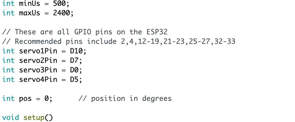
The servos only move 90 degrees or so. So I tried to adjust the min and maxUs that refers to the angle of the servos but that wont work eiter.
int minUs = 500;   //1000 CHANGED THIS
int maxUs = 3000;   //2000 CHANGED THIS
/*
 * ESP32 Servo Example Using Arduino ESP32 Servo Library
 * John K. Bennett
 * March, 2017
 *
 * This sketch uses the Arduino ESP32 Servo Library to sweep 4 servos in sequence.
 *
 * Different servos require different pulse widths to vary servo angle, but the range is
 * an approximately 500-2500 microsecond pulse every 20ms (50Hz). In general, hobbyist servos
 * sweep 180 degrees, so the lowest number in the published range for a particular servo
 * represents an angle of 0 degrees, the middle of the range represents 90 degrees, and the top
 * of the range represents 180 degrees. So for example, if the range is 1000us to 2000us,
 * 1000us would equal an angle of 0, 1500us would equal 90 degrees, and 2000us would equal 1800
 * degrees.
 *
 * Circuit:
 * Servo motors have three wires: power, ground, and signal. The power wire is typically red,
 * the ground wire is typically black or brown, and the signal wire is typically yellow,
 * orange or white. Since the ESP32 can supply limited current at only 3.3V, and servos draw
 * considerable power, we will connect servo power to the VBat pin of the ESP32 (located
 * near the USB connector). THIS IS ONLY APPROPRIATE FOR SMALL SERVOS.
 *
 * We could also connect servo power to a separate external
 * power source (as long as we connect all of the grounds (ESP32, servo, and external power).
 * In this example, we just connect ESP32 ground to servo ground. The servo signal pins
 * connect to any available GPIO pins on the ESP32 (in this example, we use pins
 * 22, 19, 23, & 18).
 *
 * In this example, we assume four Tower Pro SG90 small servos.
 * The published min and max for this servo are 500 and 2400, respectively.
 * These values actually drive the servos a little past 0 and 180, so
 * if you are particular, adjust the min and max values to match your needs.
 * Experimentally, 550 and 2350 are pretty close to 0 and 180.
 */

#include <ESP32Servo.h>

// create four servo objects
Servo servo1;
Servo servo2;
Servo servo3;
Servo servo4;
Servo servo5;
// Published values for SG90 servos; adjust if needed
int minUs = 1000;
int maxUs = 2000;

// These are all GPIO pins on the ESP32
// Recommended pins include 2,4,12-19,21-23,25-27,32-33
// for the ESP32-S2 the GPIO pins are 1-21,26,33-42
// for the ESP32-S3 the GPIO pins are 1-21,35-45,47-48
// for the ESP32-C3 the GPIO pins are 1-10,18-21
#if defined(CONFIG_IDF_TARGET_ESP32C3)
int servo1Pin = D0;      //GPIO2
int servo2Pin = D5;      //GPIO21
int servo3Pin = D7;      //GPIO20
int servo4Pin = D10;     //GPIO9
#endif

int pos = 0;      // position in degrees
ESP32PWM pwm;
void setup() {
    // Allow allocation of all timers
    ESP32PWM::allocateTimer(0);
    ESP32PWM::allocateTimer(1);
    ESP32PWM::allocateTimer(2);
    ESP32PWM::allocateTimer(3);
    Serial.begin(115200);
    servo1.setPeriodHertz(50);      // Standard 50hz servo
    servo2.setPeriodHertz(50);      // Standard 50hz servo
    servo3.setPeriodHertz(330);      // Standard 50hz servo
    servo4.setPeriodHertz(200);      // Standard 50hz servo
    //servo5.setPeriodHertz(50);      // Standard 50hz servo

}

void loop() {
    servo1.attach(servo1Pin, minUs, maxUs);
    servo2.attach(servo2Pin, minUs, maxUs);
#if defined(CONFIG_IDF_TARGET_ESP32S2) || defined(CONFIG_IDF_TARGET_ESP32C3)
    pwm.attachPin(37, 10000);//10khz
#elif defined(CONFIG_IDF_TARGET_ESP32C3)
    pwm.attachPin(7, 10000);//10khz
#else
    pwm.attachPin(27, 10000);//10khz
#endif
    servo3.attach(servo3Pin, minUs, maxUs);
    servo4.attach(servo4Pin, minUs, maxUs);

    //servo5.attach(servo5Pin, minUs, maxUs);


    for (pos = 0; pos <= 180; pos += 1) { // sweep from 0 degrees to 180 degrees
        // in steps of 1 degree
        servo1.write(pos);
        delay(1);             // waits 20ms for the servo to reach the position
    }
    for (pos = 180; pos >= 0; pos -= 1) { // sweep from 180 degrees to 0 degrees
        servo1.write(pos);
        delay(1);
    }

    for (pos = 0; pos <= 180; pos += 1) { // sweep from 0 degrees to 180 degrees
        // in steps of 1 degree
        servo2.write(pos);
        delay(1);             // waits 20ms for the servo to reach the position
    }
    for (pos = 180; pos >= 0; pos -= 1) { // sweep from 180 degrees to 0 degrees
        servo2.write(pos);
        delay(1);
    }

    for (pos = 0; pos <= 180; pos += 1) { // sweep from 0 degrees to 180 degrees
        // in steps of 1 degree
        servo3.write(pos);
        delay(1);             // waits 20ms for the servo to reach the position
    }
    for (pos = 180; pos >= 0; pos -= 1) { // sweep from 180 degrees to 0 degrees
        servo3.write(pos);
        delay(1);
    }

    for (pos = 0; pos <= 180; pos += 1) { // sweep from 0 degrees to 180 degrees
        // in steps of 1 degree
        servo4.write(pos);
        delay(1);             // waits 20ms for the servo to reach the position
    }
    for (pos = 180; pos >= 0; pos -= 1) { // sweep from 180 degrees to 0 degrees
        servo4.write(pos);
        delay(1);
    }
    for (pos = 0; pos <= 180; pos += 1) { // sweep from 0 degrees to 180 degrees
        // in steps of 1 degree
        servo5.write(pos);
        delay(1);             // waits 20ms for the servo to reach the position
    }
    for (pos = 180; pos >= 0; pos -= 1) { // sweep from 180 degrees to 0 degrees
        servo5.write(pos);
        delay(1);
    }
    servo1.detach();
    servo2.detach();;
    servo3.detach();
    servo4.detach();
    pwm.detachPin(27);

    delay(5000);

}
Everything with this xiao esp32-c3 board sucks.
I can try to move servos with the LEDC examples. The LED control (LEDC) peripheral is primarly designed to control the intensity of LEDs, although it can also be used to generate PWM signals for other purposes.
The world wide web sais this library would work. OMG this works!!!!!!!!!!
Used the easiest example and it worked.
/*
  Controls servo position from 0-180 degrees and back
  https://wokwi.com/projects/350037178957431378
  by dlloydev, December 2022.
*/

#include <Servo.h>

Servo myservo = Servo();

const int servoPin = D0;

void setup() {
}

void loop() {
  for (int pos = 0; pos <= 180; pos++) {  // go from 0-180 degrees
    myservo.write(servoPin, pos);        // set the servo position (degrees)
    delay(15);
  }
  for (int pos = 180; pos >= 0; pos--) {  // go from 180-0 degrees
    myservo.write(servoPin, pos);        // set the servo position (degrees)
    delay(15);
  }
}
But if I want multiple servos it won’t work.
#include <Servo.h>

Servo myservo = Servo();

const int servoPin1 = D0;
const int servoPin2 = D5;
const int servoPin3 = D7;
const int servoPin4 = D10;

void setup() {
}

void loop() {
  for (int pos = 0; pos <= 180; pos++) {  // go from 0-180 degrees
    myservo.write(servoPin1, pos);        // set the servo position (degrees)
    myservo.write(servoPin2, pos);
    myservo.write(servoPin3, pos);
    myservo.write(servoPin4, pos);
    delay(15);
  }
  for (int pos = 180; pos >= 0; pos--) {  // go from 180-0 degrees
    myservo.write(servoPin1, pos);        // set the servo position (degrees)
    myservo.write(servoPin2, pos);
    myservo.write(servoPin3, pos);
    myservo.write(servoPin4, pos);
    delay(15);
  }

}
uhhh duhhuuuu. This library is called esp32s2-analogwrite. I need analog pins. let’s try it out.
allrightttttt babyyyyyyyyy! This works!
#include <Servo.h>

Servo myservo = Servo();

const int servoPin1 = D0;
const int servoPin2 = D1;
const int servoPin3 = D2;
const int servoPin4 = D3;

void setup() {
}

void loop() {
  for (int pos = 0; pos <= 180; pos++) {  // go from 0-180 degrees
    myservo.write(servoPin1, pos);        // set the servo position (degrees)
    myservo.write(servoPin2, pos);
    myservo.write(servoPin3, pos);
    myservo.write(servoPin4, pos);
    delay(15);
  }
  for (int pos = 180; pos >= 0; pos--) {  // go from 180-0 degrees
    myservo.write(servoPin1, pos);        // set the servo position (degrees)
    myservo.write(servoPin2, pos);
    myservo.write(servoPin3, pos);
    myservo.write(servoPin4, pos);
    delay(15);
  }

}
I tried to controll 2 servos with a joystick. It kind of works but I think the mapping is not correct yet.
#include <Servo.h>

Servo myservo = Servo();

const int servoPin1 = D0;
const int servoPin2 = D1;
///const int servoPin3 = D2;
//const int servoPin4 = D3;

const int joyX1 = D2;
const int joyY1 = D3;

int joyVal;

void setup() {
}

void loop() {

    joyVal = analogRead(joyX1);
    joyVal = map (joyVal, 0, 1023, 0, 180);
    myservo.write(servoPin1, joyVal);        // set the servo position (degrees)
    joyVal = analogRead(joyY1);
    joyVal = map (joyVal, 0, 1023, 0, 180);
    myservo.write(servoPin2, joyVal);

}
This works better. I changed the the mapping to 0, 254, 0,180 and powered the joysticks directly to the esp instead of the external power supply that I use for the servos.
#include <Servo.h>

Servo myservo = Servo();

const int servoPin1 = D0;
const int servoPin2 = D1;
///const int servoPin3 = D2;
//const int servoPin4 = D3;

const int joyX1 = D2;
const int joyY1 = D3;

int joyVal;

void setup() {
}

void loop() {

    joyVal = analogRead(joyX1);
    joyVal = map (joyVal, 0, 254, 0, 180);
    myservo.write(servoPin1, joyVal);        // set the servo position (degrees)
    joyVal = analogRead(joyY1);
    joyVal = map (joyVal, 0, 254, 0, 180);
    myservo.write(servoPin2, joyVal);

}
Controller
2 buttons worked. Now only one.. Not sure why.
Stepper
First I thought my stepper PCB was not working. After changing the code and tried with a 4th stepper it worked fine......... The vRef was ok steps also. Maybe I used a few weird stepper that aren’t compatible with the driver.
Servos + esp32-c3
I want to control 4 servos with 1 esp32-c3 xiao board.
See the schematics and pcb below.
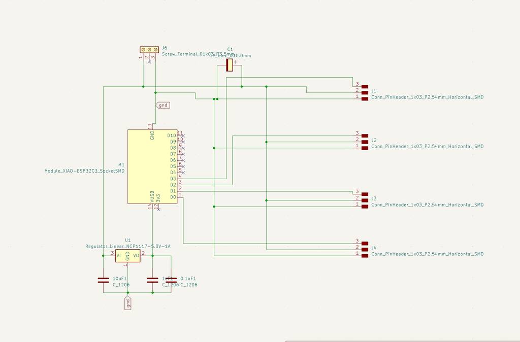

It’s a hassle to control 4 servos at the same time with a xiao esp32-c3 board.
With this code I can only control 2 servos at once.
I have the following pins connected.
d0
d5
d7
d10
The order is important. If I start with d7 and 10 in my code these to servos work. If I start with d0 and d5 first these servos respond. So my PCB is work fine but de XIAO board is acting weird.
Got al my servos working with an Arduino at the same time! This is good and bad news. My PCB is probably fine but the xiao board is being a fucker because it won’t cooparate.
OK!!! I got it to work now with the following code!!
/*
 * ESP32 Servo Example Using Arduino ESP32 Servo Library
 * John K. Bennett
 * March, 2017
 *
 * This sketch uses the Arduino ESP32 Servo Library to sweep 4 servos in sequence.
 *
 * Different servos require different pulse widths to vary servo angle, but the range is
 * an approximately 500-2500 microsecond pulse every 20ms (50Hz). In general, hobbyist servos
 * sweep 180 degrees, so the lowest number in the published range for a particular servo
 * represents an angle of 0 degrees, the middle of the range represents 90 degrees, and the top
 * of the range represents 180 degrees. So for example, if the range is 1000us to 2000us,
 * 1000us would equal an angle of 0, 1500us would equal 90 degrees, and 2000us would equal 1800
 * degrees.
 *
 * Circuit:
 * Servo motors have three wires: power, ground, and signal. The power wire is typically red,
 * the ground wire is typically black or brown, and the signal wire is typically yellow,
 * orange or white. Since the ESP32 can supply limited current at only 3.3V, and servos draw
 * considerable power, we will connect servo power to the VBat pin of the ESP32 (located
 * near the USB connector). THIS IS ONLY APPROPRIATE FOR SMALL SERVOS.
 *
 * We could also connect servo power to a separate external
 * power source (as long as we connect all of the grounds (ESP32, servo, and external power).
 * In this example, we just connect ESP32 ground to servo ground. The servo signal pins
 * connect to any available GPIO pins on the ESP32 (in this example, we use pins
 * 22, 19, 23, & 18).
 *
 * In this example, we assume four Tower Pro SG90 small servos.
 * The published min and max for this servo are 500 and 2400, respectively.
 * These values actually drive the servos a little past 0 and 180, so
 * if you are particular, adjust the min and max values to match your needs.
 * Experimentally, 550 and 2350 are pretty close to 0 and 180.
 */

#include <ESP32Servo.h>

// create four servo objects
Servo servo1;
Servo servo2;
Servo servo3;
Servo servo4;
Servo servo5;
// Published values for SG90 servos; adjust if needed
int minUs = 1000;
int maxUs = 2000;

// These are all GPIO pins on the ESP32
// Recommended pins include 2,4,12-19,21-23,25-27,32-33
// for the ESP32-S2 the GPIO pins are 1-21,26,33-42
// for the ESP32-S3 the GPIO pins are 1-21,35-45,47-48
// for the ESP32-C3 the GPIO pins are 1-10,18-21
#if defined(CONFIG_IDF_TARGET_ESP32C3)
int servo1Pin = D0;      //GPIO2
int servo2Pin = D5;      //GPIO21
int servo3Pin = D7;      //GPIO20
int servo4Pin = D10;     //GPIO9
#endif

int pos = 0;      // position in degrees
ESP32PWM pwm;
void setup() {
    // Allow allocation of all timers
    ESP32PWM::allocateTimer(0);
    ESP32PWM::allocateTimer(1);
    ESP32PWM::allocateTimer(2);
    ESP32PWM::allocateTimer(3);
    Serial.begin(115200);
    servo1.setPeriodHertz(50);      // Standard 50hz servo
    servo2.setPeriodHertz(50);      // Standard 50hz servo
    servo3.setPeriodHertz(330);      // Standard 50hz servo
    servo4.setPeriodHertz(200);      // Standard 50hz servo
    //servo5.setPeriodHertz(50);      // Standard 50hz servo

}

void loop() {
    servo1.attach(servo1Pin, minUs, maxUs);
    servo2.attach(servo2Pin, minUs, maxUs);
#if defined(CONFIG_IDF_TARGET_ESP32S2) || defined(CONFIG_IDF_TARGET_ESP32C3)
    pwm.attachPin(37, 10000);//10khz
#elif defined(CONFIG_IDF_TARGET_ESP32C3)
    pwm.attachPin(7, 10000);//10khz
#else
    pwm.attachPin(27, 10000);//10khz
#endif
    servo3.attach(servo3Pin, minUs, maxUs);
    servo4.attach(servo4Pin, minUs, maxUs);

    //servo5.attach(servo5Pin, minUs, maxUs);


    for (pos = 0; pos <= 180; pos += 1) { // sweep from 0 degrees to 180 degrees
        // in steps of 1 degree
        servo1.write(pos);
        delay(1);             // waits 20ms for the servo to reach the position
    }
    for (pos = 180; pos >= 0; pos -= 1) { // sweep from 180 degrees to 0 degrees
        servo1.write(pos);
        delay(1);
    }

    for (pos = 0; pos <= 180; pos += 1) { // sweep from 0 degrees to 180 degrees
        // in steps of 1 degree
        servo2.write(pos);
        delay(1);             // waits 20ms for the servo to reach the position
    }
    for (pos = 180; pos >= 0; pos -= 1) { // sweep from 180 degrees to 0 degrees
        servo2.write(pos);
        delay(1);
    }

    for (pos = 0; pos <= 180; pos += 1) { // sweep from 0 degrees to 180 degrees
        // in steps of 1 degree
        servo3.write(pos);
        delay(1);             // waits 20ms for the servo to reach the position
    }
    for (pos = 180; pos >= 0; pos -= 1) { // sweep from 180 degrees to 0 degrees
        servo3.write(pos);
        delay(1);
    }

    for (pos = 0; pos <= 180; pos += 1) { // sweep from 0 degrees to 180 degrees
        // in steps of 1 degree
        servo4.write(pos);
        delay(1);             // waits 20ms for the servo to reach the position
    }
    for (pos = 180; pos >= 0; pos -= 1) { // sweep from 180 degrees to 0 degrees
        servo4.write(pos);
        delay(1);
    }
    for (pos = 0; pos <= 180; pos += 1) { // sweep from 0 degrees to 180 degrees
        // in steps of 1 degree
        servo5.write(pos);
        delay(1);             // waits 20ms for the servo to reach the position
    }
    for (pos = 180; pos >= 0; pos -= 1) { // sweep from 180 degrees to 0 degrees
        servo5.write(pos);
        delay(1);
    }
    servo1.detach();
    servo2.detach();;
    servo3.detach();
    servo4.detach();
    pwm.detachPin(27);

    delay(5000);

}
What’s up?????
Normaly a couple of servos is easy to control. But with the esp32-c3 XIAO seed it’s a hassle. Why?
I got only a few servos working at the same time. This is probably because of a Timer problem. See picture below.
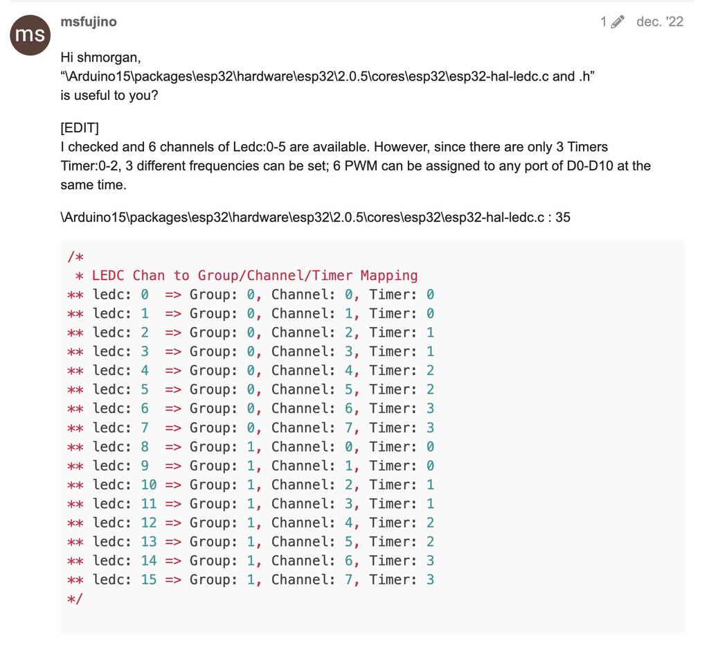
Why do we need this ESP32_C3_ISR_Servo library
This library enables you to use 1 Hardware Timer on an ESP32_C3-based board to control up to 16 independent servo motors.
Important Notes about using ISR
Inside the attached function, delay() won’t work and the value returned by millis() will not increment. Serial data received while in the function may be lost. You should declare as volatile any variables that you modify within the attached function.
Typically global variables are used to pass data between an ISR and the main program. To make sure variables shared between an ISR and the main program are updated correctly, declare them as volatile.
Avoid using Serial.print()-related functions inside ISR. Just for temporary debug purpose, but even this also can crash the system any time. Beware.
Your functions are now part of ISR (Interrupt Service Routine), and must be lean / mean, and follow certain rules. More to read on:
Wireless connection
Maybe check this out
Followed this tutorial
To communicate via ESP-NOW, you need to know the MAC Address of the ESP32 receiver
Ran this code on my Xiao esp32-c3.
#include "WiFi.h"

void setup(){
  Serial.begin(115200);
  WiFi.mode(WIFI_MODE_STA);
  Serial.println(WiFi.macAddress());
}

void loop(){

}
Opened my serial and got the following adress: 12:04:05.063 -> 58:CF:79:F1:39:C0 This is the adress of my reciever! Important that you write it like this in your IDE 0x58, 0xCF, 0x79, 0xF1, 0x39, 0xC0
NEW
0x58, 0xCF, 0x79, 0xEB, 0x8E, 0xC0 //58:CF:79:EB:8E:C0