11. Input devices
Assignment
Individual assignment:
measure something: add a sensor to a microcontroller board
that you have designed and read it
Group assignment:
probe an input device’s analog levels and digital signals
Potentionmeter
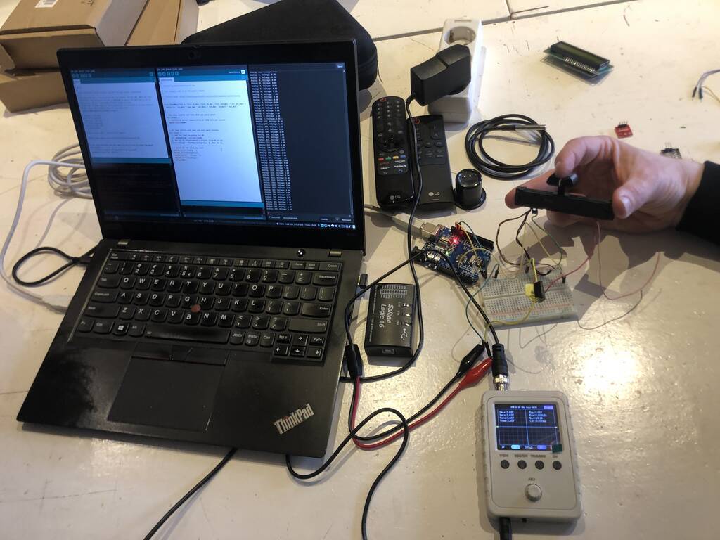
The first input device we measured was a Potentiometer. We used this link for the code. You can see that the value 0 - 1023 was set equal to 0 - 5 V. The small grey device is a cheap oscilloscope where we measured the analog output with.
/*
 * Created by ArduinoGetStarted.com
 *
 * This example code is in the public domain
 *
 * Tutorial page: https://arduinogetstarted.com/tutorials/arduino-potentiometer
 */

float floatMap(float x, float in_min, float in_max, float out_min, float out_max) {
  return (x - in_min) * (out_max - out_min) / (in_max - in_min) + out_min;
}

// the setup routine runs once when you press reset:
void setup() {
  // initialize serial communication at 9600 bits per second:
  Serial.begin(9600);
}

// the loop routine runs over and over again forever:
void loop() {
  // read the input on analog pin A0:
  int analogValue = analogRead(A0);
  // Rescale to potentiometer's voltage (from 0V to 5V):
  float voltage = floatMap(analogValue, 0, 1023, 0, 5);

  // print out the value you read:
  Serial.print("Analog: ");
  Serial.print(analogValue);
  Serial.print(", Voltage: ");
  Serial.println(voltage);
  delay(1000);
}
Here you can see the change of the value.
We also used this small oscillopscope.
Rotary Encoder
We also worked with a rotary encoder. This is a kind of a potentiometer without an end and a start and with a push button (SW). It comunicates with two digital pins, a clock and a data pin.
The code.
#define PIN_CLOCK   2
#define PIN_DATA    3
#define PIN_SWITCH  4

uint8_t processed = 0;
uint8_t count = 127;

void setup() {
  pinMode(PIN_CLOCK, INPUT);
  pinMode(PIN_DATA, INPUT);
  pinMode(PIN_SWITCH, INPUT_PULLUP);
  Serial.begin(115200);
}

void loop() {
  if (digitalRead(PIN_CLOCK) == 0 && processed == 0) {
    delay(5);
    processed = 1;
    if (digitalRead(PIN_DATA) == 1) {
      Serial.println("counterclockwise");
      count--;
    } else {
      Serial.println("clockwise");
      count++;
    }
    Serial.println(count);
  }
  if (digitalRead(PIN_CLOCK) == 1) {
    delay(5);
    processed = 0;
  }
  Serial.println(digitalRead(PIN_SWITCH));
  delay(100);
}
Result. If you turn or press the knob you can see the result in the serial. First the button wasn’t working because it was ‘floating’ it measured less voltage then it needed. So we changed the input to input_pullup.
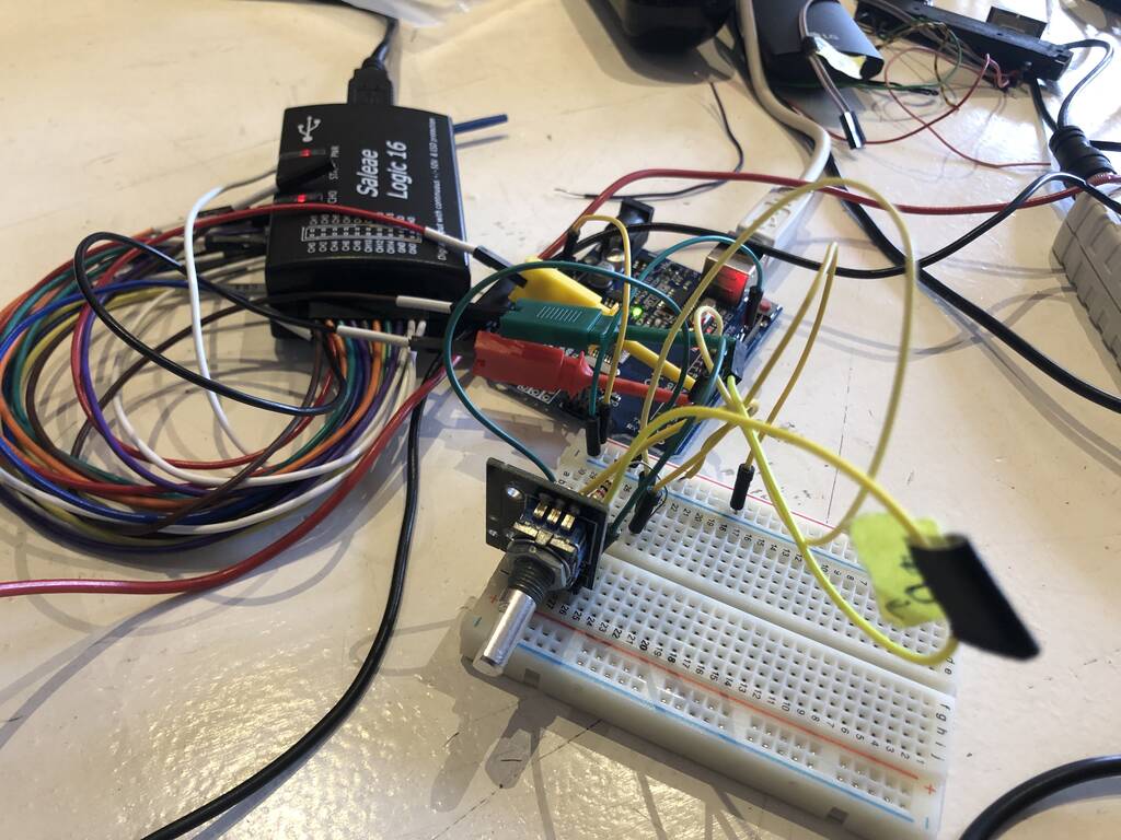
We connected the Saleae Logic 16 to check the digital signal.
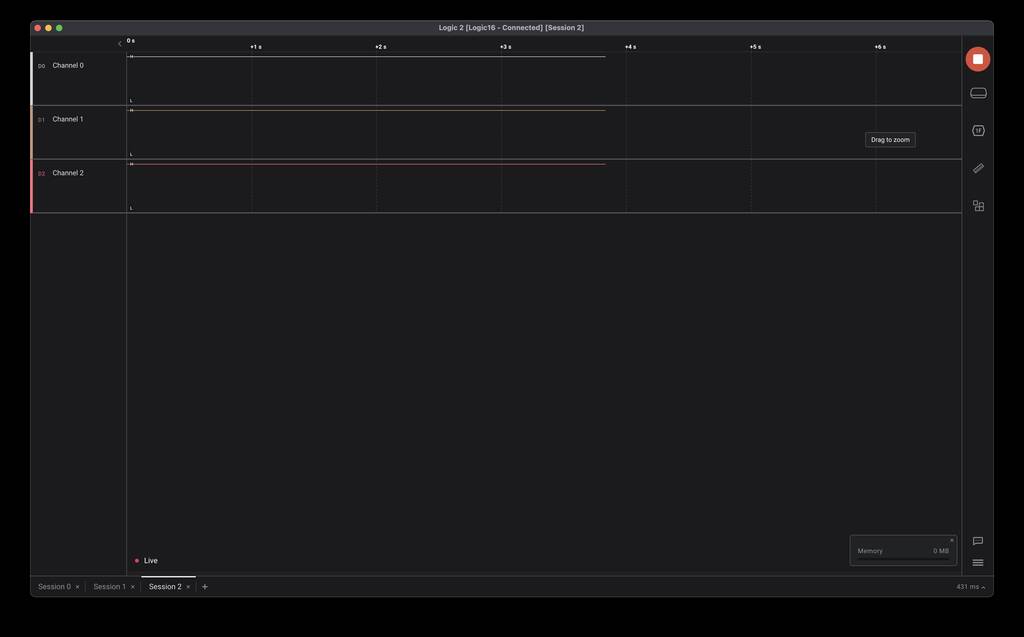
Channel 0 is the button.
Channel 1 is data.
Channel 2 is CLK.
If the clock is high the data is low. This means that its moving clockwise.
I tweaked the code a bit with Pieter his help because sometimes while rotating the know it was measuring the wrong value (clockwise / counterclockwise). We defined the delay and playd with the number a bit. A delay of 2 worked nice.
#define PIN_CLOCK   2
#define PIN_DATA    3
#define PIN_SWITCH  4
#define DELAY       2
uint8_t processed = 0;
uint8_t count = 127;

void setup() {
  pinMode(PIN_CLOCK, INPUT);
  pinMode(PIN_DATA, INPUT);
  pinMode(PIN_SWITCH, INPUT_PULLUP);
  Serial.begin(115200);
}

void loop() {
  if (digitalRead(PIN_CLOCK) == 0 && processed == 0) {
    delay(DELAY);
    processed = 1;
    if (digitalRead(PIN_DATA) == 1) {
      Serial.println("counterclockwise");
      count--;
    } else {
      Serial.println("clockwise");
      count++;
    }
    Serial.println(count);
  }
  if (digitalRead(PIN_CLOCK) == 1) {
    delay(DELAY);
    processed = 0;
  }
}
By decreasing the delay the rotary was measuring more exact.
Ultrasonic sensor
I connected an ultrasonic sensor but it was working pretty messy. I might experiment with it a bit more later on.
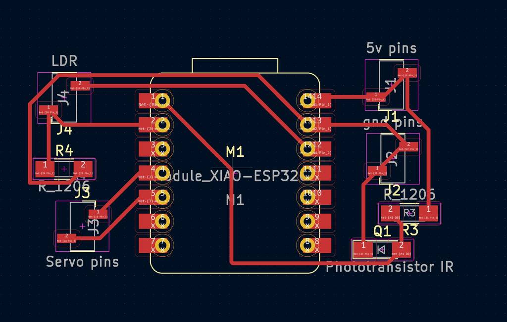
light controlled servo
I wanted to control a servo with sensors. Eventually I want to create a similar system in my final project. I want to work with a MOSFET. But I didn’t succeed this week.
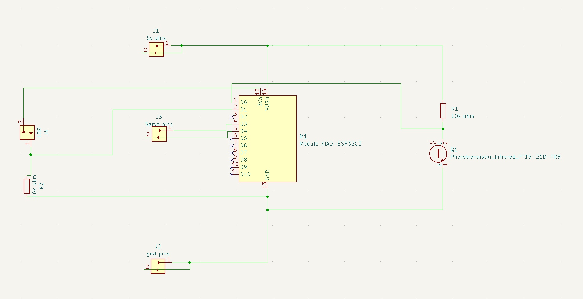
I implemented a Infrared Phototransistor and a LDR sensor.
Mosfet data sheet - digikey
phototransistor - digikey
I created this PCB.
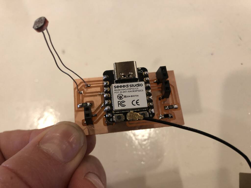
Somehow it’s not easy to run a servo on a esp32-c3 but I found a library that works.
library
example
I integrated a LDR sensor. a servo and a ESP32-C3. Uploaded the following code. But it didn’t work. (I found out in the following weeks that if you use this library it does work)
#include <pwmWrite.h>

Pwm pwm = Pwm();

const int servoPin4 = 4;

void setup() {
}

void loop() {
  int lightValue = analogRead(D1);  // position in degrees (maybe D1 instead of A1)

  lightValue = map (lightValue, 0 1023, 0, 180);

  pwm.writeServo(servoPin4, lightValue);

  }
}
I’ll give it a shot if it will work on a UNO. This worked. It probably didn’t work because the libraries are different for the uno and the xiao esp32-c3. I don’t feel like spending a lot of time in getting this to work on the ESP now so I’ll continue on the Uno.
#include <Servo.h>

Servo servo1;

void setup() {
  // put your setup code here, to run once:
  Serial.begin(9600);
  servo1.attach(9);

}

void loop() {
  // put your main code here, to run repeatedly:
int lightValue = analogRead(A0);

lightValue = map (lightValue, 0, 1023, 0, 180);

servo1.write (lightValue);
Serial.println(lightValue);
}
But I don’t get why my serial is printing this value now… I think it’s because I connected it to pin 9 which is a digital pin. Digital pins read high an low. Analog pins can read values. On this uno it could read between 0 - 1023 because it has an 8 bit-resolution.
I changed the values for this pin to see if I can move the servo 180 degrees instead of a little bit. I kind of use the sensor as a button now.
#include <Servo.h>

Servo servo1;

void setup() {
  // put your setup code here, to run once:
  Serial.begin(9600);
  servo1.attach(9);

}

void loop() {
  // put your main code here, to run repeatedly:
int lightValue = analogRead(A0);

lightValue = map (lightValue, 0, 100, 0, 180);

servo1.write (lightValue);
Serial.println(lightValue);
}
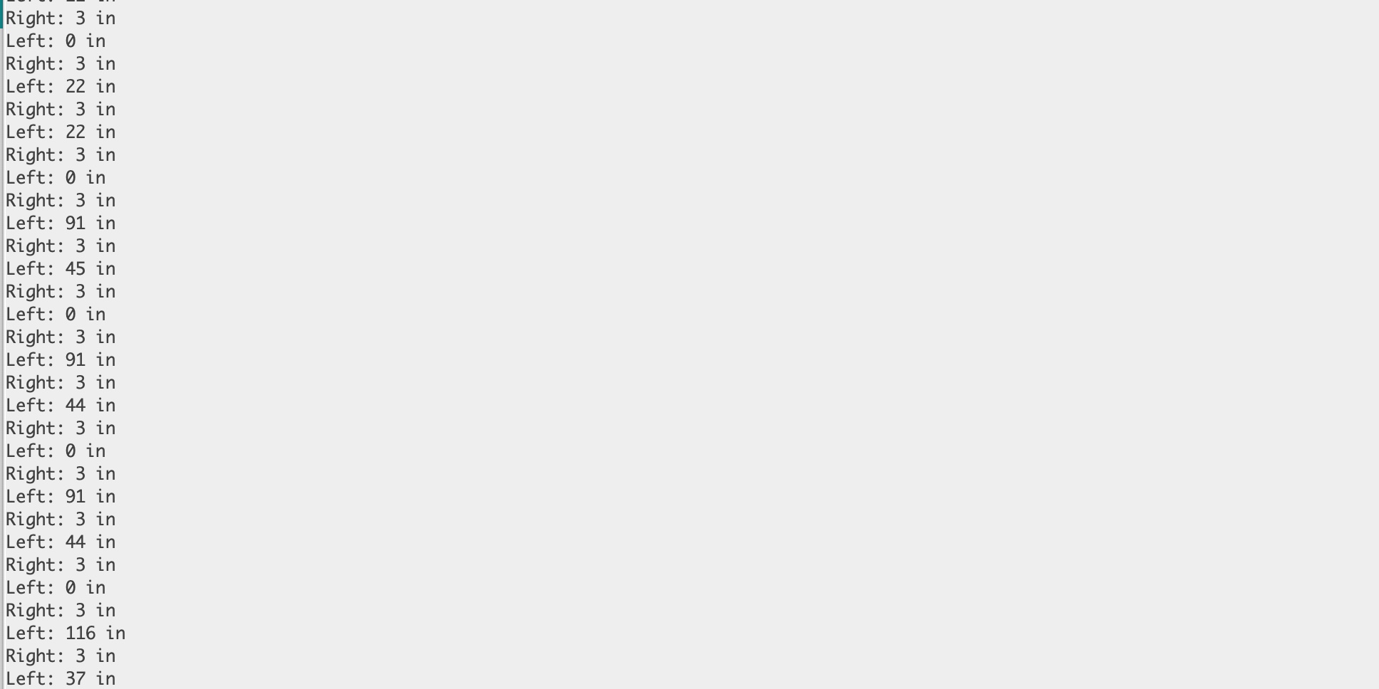
Motion following Servo
I followed this link to make a motion following servo. I used 2 ultrasonic range sensors.
I made a crappy instable design but it worked out.
/*************************************************************************************************
**************************************************************************************************
Motion Follow
Created by Calvin Kielas-Jensen

Using an Arduino UNO, check Instructables.com for the circuit diagram.

This script allows two ultrasonic range sensors to follow movement while mounted on the top of a
servo. The distance threshold can be changed but should not be set too far as the sensors will
begin to fail.

Anyone is welcome to use and modify this code as long as I am given credit. Thank you for
respecting the open source movement!
**************************************************************************************************
*************************************************************************************************/

#include <Servo.h>

Servo myservo;

const int Lin = 10, Rin = 12, Lout = 11, Rout = 13, serv = 9; //setting sensor pins and servo pin

// establish variables for duration
// and the distance result in inches
long Rduration, Lduration, Rinches, Linches;

int threshold = 10; //Sensor threshold in inches

int angle = 80; //Initial angle

boolean debug = false; //Serial communication for debuging. Set to true for serial communication.

void setup() {
  // initialize serial communication:
  if (debug)
  {
    Serial.begin(9600);
  }
  myservo.attach(9); //attach servo to pin 9
}

void loop()
{

  //Most of the sensor code has been taken from David Mellis's PING sensor code
  //I modified it for a 4 pin sensor as oppsed to the 3 pin sensor
  // Give a short LOW pulse beforehand to ensure a clean HIGH pulse:
  pinMode(Rout, OUTPUT);
  digitalWrite(Rout, LOW);
  delayMicroseconds(2);
  digitalWrite(Rout, HIGH);
  delayMicroseconds(5);
  digitalWrite(Rout, LOW);

  Rduration = pulseIn(Rin, HIGH);

  pinMode(Lout, OUTPUT);
  digitalWrite(Lout, LOW);
  delayMicroseconds(2);
  digitalWrite(Lout, HIGH);
  delayMicroseconds(5);
  digitalWrite(Lout, LOW);

  Lduration = pulseIn(Lin, HIGH);

  // convert the time into a distance
  Rinches = microsecondsToInches(Rduration);
  Linches = microsecondsToInches(Lduration);

  if (debug)
  {
    Serial.print("Left: ");
    Serial.print(Linches);
    Serial.println(" in");
    Serial.print("Right: ");
    Serial.print(Rinches);
    Serial.println(" in");
  }
  follow();

}

long microsecondsToInches(long microseconds)
{
  // According to Parallax's datasheet for the PING))), there are
  // 73.746 microseconds per inch (i.e. sound travels at 1130 feet per
  // second).  This gives the distance travelled by the ping, outbound
  // and return, so we divide by 2 to get the distance of the obstacle.
  // See: http://www.parallax.com/dl/docs/prod/acc/28015-PING-v1.3.pdf
  return microseconds / 74 / 2;
}

void follow()
{
  if (Linches <= threshold || Rinches <= threshold)
  {
    if (Linches + 2 < Rinches)
    {
      angle = angle - 2;
    }
    if (Rinches + 2 < Linches)
    {
      angle = angle + 2;
    }
  }
  if (angle > 160)
  {
    angle = 160;
  }
  if (angle < 0)
  {
    angle = 0;
  }
  myservo.write(angle);

}

ESP32-CAM
I did a lot of little tests but nothing worked profi enough for my final project. First, what do I exactly want for my final project?
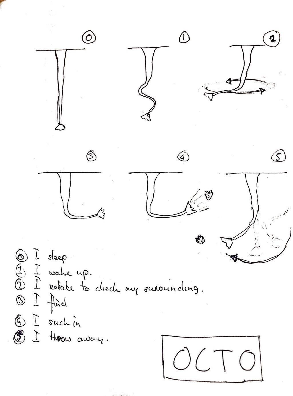
So I need a sensor to wake up.
This is a really good link that explains two sensors that I might want to use.
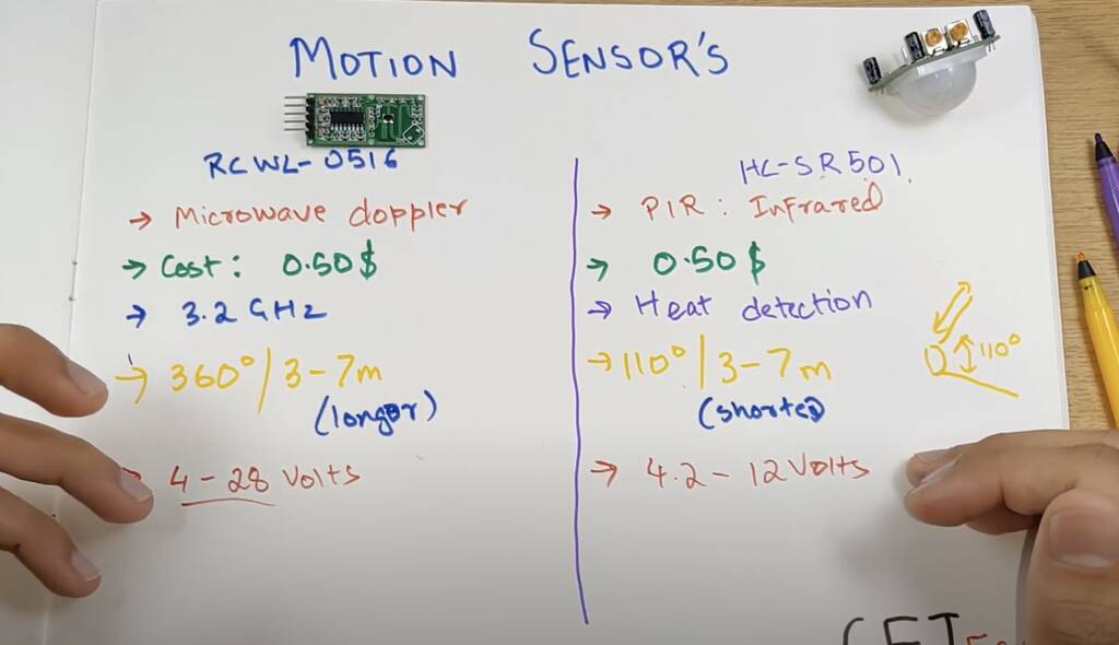
Will I go for the
- RCWL-0516 Microwave
- HC-SR501 PIR Motion sensors
Finally I need a motion tracking system. I would love to use a camera with openCV. This link is extremly cool. Also take a look into the links they attached in their documentation.
At the Waag we have an ESP32-CAM module. This microcontroller with camera would be ideal. But we don’t have that one laying around. Maybe later. Let’s try to get the ESP32-cam module going with maybe something like OpenCV.
Programming
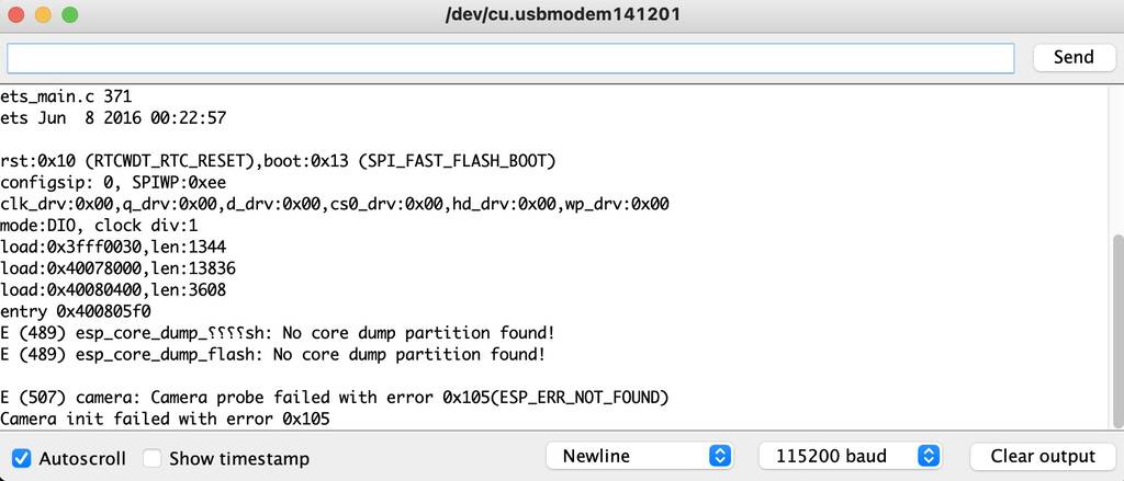
I need to program the esp32-cam. I have my FDTI programmer not within reach so I’ll try it out with an uno instead.
Omg… It took my 2 hours till I threw the Uno out of the window. I took a simple FTDI that Henk gave me and it worked instantly. You can work with any tutorial online. Just make sure that you define the correct camera model. The #define CAMERA_MODEL_AI_THINKER // Has PSRAM worked for me. I have a ESP32-S chip. Maybe you have something different.
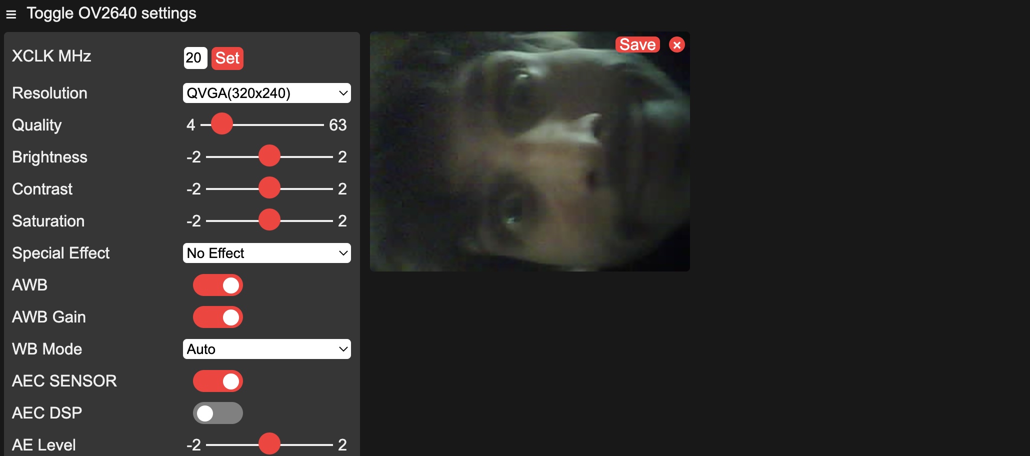
So I got my Esp working now with a local server. What next?
I want motion tracking with my esp32-CAM. I looked into OpenCV. But to run OpenCV as a stand alone on a MCU I need a lot of space. If I eventually decide to do that I can follow this link.
After some research I found a view examples of motion tracking projects with a ESP32-cam and servo’s. But for these projects you have an X and a Y axes servo. My project is a bit more complicated. I think I need to make a simple model to run a view tests.