Characteristics of the Xiao boards
For this Fab Academy year, we're moving to cheap but powerful microprocessors. A microcontroller is a chip with a microproccessor, memory, counters, and built-in peripherals such as digital and analog input/output ports. The microcontrollers that we are going to use are already soldered on boards that have native USB connectivity. This removes the need for programmers because we can program them directly over USB.
The board form factor is XIAO which means "Tiny but powerful" in Chinese. The size is about that of a thumb and XIAO boards have 14 pins, a boot and reset button, and a female USB-C port. Unfortunately, we cannot directly plug in the boards, but we require a male-male USB-C cable. Henk lend us one but he wants them back, so I have to buy my own.
We received two Xiao boards from Henk on which we can solder pins so we can move the Xiao boards from project to project, reprogramming them for the specific project. One Xiao board has the Espressif ESP32C3 chip with a RISC-V architecture that has Wifi and Bluetooth connectivity. The other Xiao board has a powerful Raspberry Pi RP2040 processor based on the ARM architecture .
Feature Comparison between Microcontrollers
For the group assignment, we compare a couple of microcontrollers. Michelle has a more thorough overview, but I find the following comparison useful.
| Features | ATTiny 84A | XIAO ESP32-C3 | XIAO RP2040 |
|---|---|---|---|
| Processor | single-core AVR | single-core RISC-V | dual-core ARM Cortex M0+ |
| Clock speed | 0-20 MHz | 0-160 MHz | 133 MHz |
| Word size | 8-bit | 32-bit | 32-bit |
| Internal Memory | 512 B | 400 KB | 264 KB |
| Flash Memory | 8 KB | 0-4 MB | 16 MB |
| ROM | 512 B EEPROM | 384 KB | 16 KB |
| Wireless | no | Bluetooth/Wifi | no |
What is interesting here is the size of the internal memory which is not large compared to processors that typically have DRAM for internal memory. This must have to do with the Harvard architecture that Neil mentioned where code and data reside in different memories. So, I assume that code will not be stored in the internal memory of 512 bytes of the AVR chip, as that would make it impossible to run any decent program, so most likely the 512 B is only for the data of your programs and the code is directly read from flash memory? I hope that I will find out more when studying one of the data sheets.
Performance Difference Microcontrollers
We decided to measure the performance difference by executing a simple benchmark that makes use of some trigonometry functions in a loop. Since we also have to study different workflows, we decided to test this in Arduino and in MicroPython , where I was responsible for the MicroPython part. We tested the Arduino Uno, the ESP32-C3, and the RP2040. Note that the Arduino Uno doesn't support MicroPython (as it contains an 8-bit processor).
The code we used for this in Arduino is:
const int BAUD_RATE = 9600;
const int ITERATIONS = 100000;

void setup() {
  // set up the serial port
  Serial.begin(BAUD_RATE);

  // wait a second
  delay(1000);
}

void loop() {
  double result = 0.0;

  int start = millis();
  for (int i = 0; i < ITERATIONS; i++) {
    result += sin(i);
  }
  int end = millis();
  Serial.println(result);
  Serial.print(end - start);
  Serial.println(" milliseconds passed to calculate");
}
The same code for MicroPython is shown below with the difference that there is a loop of ten iterations in which the measurements are done, compared to an infinite loop in Arduino.
import time
import math

ITERATIONS = 100000

def benchmark():
    result = 0.0

    start = time.ticks_ms()
    for i in range(ITERATIONS):
        result += math.sin(i)
    delta = time.ticks_diff(time.ticks_ms(), start)
    print(result)
    print(delta)

for i in range(10):
    print(f"attempt {i}")
    benchmark()
    print()
The performance difference is shown below:
| Programming Environment | Time Arduino Uno (ms) | Time ESP32-C3 (ms) | Time RP2040 (ms) |
|---|---|---|---|
| Arduino | 13538 | 3741 | 1763 |
| MicroPython | - | 26017 | 2815 |
| MicroPython (viper) | - | error | 2298 |
| MicroPython (native) | - | error | 2407 |
Interesting here is that the ESP32-C3 is about twice as slow with Arduino,
but that with MicroPython, it is almost a factor 9 slower. I've tried to
add the annotations
@micropython.viper
and
@micropython.native
but this led to error messages that state
that the these annotations are invalid. It simply seems not to be
supported on the ESP32-C3. However, with the RP2040, the annotations are
supported and it leads to a bit different execution times as shown in the
table above.
Another very interesting issue is that with enabling
@micropython.viper
, I have to remove the constant because it
shows an error message with regards to the loop. Making the reference
ITERATIONS
a constant in the loop (so
100000
) makes the code
work. This seemed to me be a bug in MicroPython but we presented the code
to Neil and he mentioned that this annotation is not a generic annotation,
but that there are limitations for the kind of Python you write. In the
Viper
documentation
states that it uses native data types that are not
necessarily compatible with Python. So, thanks Neil for the clarification,
and I think I should have simply checked the Viper documentation...
Another remark is that when enabling viper and native execution, the serial port is unresponsive in the sense that the print statements happen at random times and not immediately. In the next section there is a video that shows this behavior.
Since viper and native execution simply don't work on the ESP32-C3, and enabling viper on the RP2040 gives us a strange error, I think we can conclude that this functionality is still experimental. My hypothesis is currently that the level of optimizations are much higher for ARM processors than for the relatively newer RISC-V architecture explained by the minor difference in performance between Arduino and MicroPython with all three MicroPython versions. I would have expected a factor 3-10 between Arduino and MicroPython on the RP2040 but when measuring, the MicroPython version is much factor and only a factor 1.5 slower.
Neil encouraged me to provide the MicroPython developers with this information. He was surprised as well that the performance difference between the interpreted and native version was so little and that the interpreted version was not that much slower.
While Michelle was working on the above benchmark, I tried to port the
LINPACK
benchmark to Arduino
to compare the performance of the RP2040 to that of an early supercomputer.
I failed to get it to run well but discovered that LINPACK makes use of
malloc()
and
free()
. I think I can get this to work if I
simply allocate memory statically, but I have to look into the code more
than I have time for currently.
Neil mentioned that he has a benchmark that computes PI that correlates well with the LINPACK benchmark. At this moment I can't find the link, though.
The MicroPython Programming Environment
The programming environment in MicroPython differs from Arduino and is much
more interactive because it has a REPL. It is not necessary to compile the
code and upload it, but instead you can communicate directly. Thonny has a
convenient Run button that copies the contents of the file into the REPL to
execute it immediately. Below is a video of the benchmark used below in
interpreted mode (the print statements happen as you would expect), viper
and native mode (where the print statements are not interactive) and using
the REPL directly to compute
2 + 3
. The video also shows the weird
behavior of the
@micropython.viper
annotation that doesn't work with
the variable
ITERATIONS
:
Programming the RP2040 and the ESP32-C3
To get started, I first choose to set up the Arduino environment after which I will try the MicroPython environment.
Arduino on the ESP32-C3
To install Arduino on my Arch Linux machine, I have to install the following packages, following the instructions for Arch Linux :
pacman -S arduino arduino-docs arduino-avr-core arduino-cli
Since we need to access to a serial port, we need to be part of group
uucp
:
sudo usermod -a -G uucp pieter
Since we changed user groups, I have to log in and out completely.
I have a USB-C hub and connecting the ESP32-C3 to this hub doesn't work.
Most likely, the USB-C port is only for charging. Connecting it directly
gives the following output with
dmesg -ew
:
[Feb16 12:04] usb 3-4: new full-speed USB device number 7 using xhci_hcd
[  +0.209405] usb 3-4: New USB device found, idVendor=303a, idProduct=1001, bcdDevice= 1.01
[  +0.000009] usb 3-4: New USB device strings: Mfr=1, Product=2, SerialNumber=3
[  +0.000003] usb 3-4: Product: USB JTAG/serial debug unit
[  +0.000003] usb 3-4: Manufacturer: Espressif
[  +0.000002] usb 3-4: SerialNumber: 58:CF:79:F1:7E:B0
[  +0.063484] cdc_acm 3-4:1.0: ttyACM0: USB ACM device
[  +0.000044] usbcore: registered new interface driver cdc_acm
[  +0.000003] cdc_acm: USB Abstract Control Model driver for USB modems and ISDN adapters
This tells us that we have should use
/dev/ttyACM0
as serial port.
In Arduino, we add the "ESP32" board package and we select the board "XIAO_ESP32C3". We try to compile a led blinking program, but we get the following error:
Arduino: 1.8.19 (Linux), Board: "XIAO_ESP32C3, Enabled, Default 4MB with spiffs (1.2MB APP/1.5MB SPIFFS), 160MHz (WiFi), QIO, 80MHz, 4MB (32Mb), 921600, None, Disabled"

Traceback (most recent call last):
  File "/home/pieter/.arduino15/packages/esp32/tools/esptool_py/4.2.1/esptool.py", line 31, in <module>
    import esptool
  File "/home/pieter/.arduino15/packages/esp32/tools/esptool_py/4.2.1/esptool/__init__.py", line 42, in <module>
    from esptool.cmds import (
  File "/home/pieter/.arduino15/packages/esp32/tools/esptool_py/4.2.1/esptool/cmds.py", line 14, in <module>
    from .bin_image import ELFFile, ImageSegment, LoadFirmwareImage
  File "/home/pieter/.arduino15/packages/esp32/tools/esptool_py/4.2.1/esptool/bin_image.py", line 14, in <module>
    from .loader import ESPLoader
  File "/home/pieter/.arduino15/packages/esp32/tools/esptool_py/4.2.1/esptool/loader.py", line 21, in <module>
    import serial
ModuleNotFoundError: No module named 'serial'
exit status 1
Error compiling for board XIAO_ESP32C3.


This report would have more information with
"Show verbose output during compilation"
option enabled in File -> Preferences.
It seems to be a Python package that is missing that
esptool.py
requires and after installing the package
python-pyserial
it worked.
Arduino on the RP2040
The RP2040 has two modes of operation, a filesytem mode and a serial mode. It is quite confusing when you require which and many times I have to disconnect and reconnect the device again.
For Arduino, we select the "Raspberry Pi Pico/RP2040" board package and select the board "Seeed XIAO RP2040". After trying to load the Blink program, it fails with the following error message:
Resetting /dev/ttyACM0
Converting to uf2, output size: 135168, start address: 0x2000
No drive to deploy.
An error occurred while uploading the sketch
This probably means that we haven't loaded the RP2040 in filesystem mode:
[ +29.007192] usb 3-4: new full-speed USB device number 11 using xhci_hcd
[  +0.225104] usb 3-4: New USB device found, idVendor=2e8a, idProduct=8042, bcdDevice= 1.00
[  +0.000010] usb 3-4: New USB device strings: Mfr=1, Product=2, SerialNumber=3
[  +0.000003] usb 3-4: Product: PicoArduino
[  +0.000002] usb 3-4: Manufacturer: Raspberry Pi
[  +0.000002] usb 3-4: SerialNumber: 415032383337300D
[  +0.007918] cdc_acm 3-4:1.0: ttyACM0: USB ACM device
[Feb16 12:51] usb usb2-port3: attempt power cycle
[  +8.433352] usb usb2-port3: unable to enumerate USB device
Holding down the boot button and resetting the device yields:
[ +17.656719] usb 3-4: new full-speed USB device number 13 using xhci_hcd
[  +0.208444] usb 3-4: New USB device found, idVendor=2e8a, idProduct=0003, bcdDevice= 1.00
[  +0.000009] usb 3-4: New USB device strings: Mfr=1, Product=2, SerialNumber=3
[  +0.000004] usb 3-4: Product: RP2 Boot
[  +0.000002] usb 3-4: Manufacturer: Raspberry Pi
[  +0.000002] usb 3-4: SerialNumber: E0C9125B0D9B
[  +0.043972] usb-storage 3-4:1.0: USB Mass Storage device detected
[  +0.000169] scsi host0: usb-storage 3-4:1.0
[  +0.000196] usbcore: registered new interface driver usb-storage
[  +0.006496] usbcore: registered new interface driver uas
[  +0.995660] scsi 0:0:0:0: Direct-Access     RPI      RP2              3    PQ: 0 ANSI: 2
[  +0.001281] sd 0:0:0:0: [sda] 262144 512-byte logical blocks: (134 MB/128 MiB)
[  +0.000691] sd 0:0:0:0: [sda] Write Protect is off
[  +0.000009] sd 0:0:0:0: [sda] Mode Sense: 03 00 00 00
[  +0.000584] sd 0:0:0:0: [sda] No Caching mode page found
[  +0.000003] sd 0:0:0:0: [sda] Assuming drive cache: write through
[  +0.006301]  sda: sda1
[  +0.000388] sd 0:0:0:0: [sda] Attached SCSI removable disk
After this, the upload works.
MicroPython on the PR2040
My initial attempt to load MicroPython on the ESP32-C3 didn't work, so I switched to the RP2040 instead. Henk had this working already, so I could make use of his knowledge.
Henk used Thonny to make this work, so after installing this, it is necessary to install MicroPython on the RP2040.
In Thonny we go to: Tools ➜ Options ➜ Interpreter and here we select "MicroPython (Raspberry Pi Pico)" as the interpreter. We can click on "Install or update MicroPython" and it should find a disk here, but it doesn't.
Checking
dmesg
it appears that the device doesn't appear in
filesystem mode:
[ +23.791940] usb 3-4: new full-speed USB device number 25 using xhci_hcd
[  +0.208186] usb 3-4: New USB device found, idVendor=2e8a, idProduct=0003, bcdDevice= 1.00
[  +0.000011] usb 3-4: New USB device strings: Mfr=1, Product=2, SerialNumber=3
[  +0.000004] usb 3-4: Product: RP2 Boot
[  +0.000003] usb 3-4: Manufacturer: Raspberry Pi
[  +0.000002] usb 3-4: SerialNumber: E0C9125B0D9B
We add to
/etc/udev/rules.d
the file
99-pico.rules
:
99-pico.rules
Then we get the following
dmesg
output:
[ +20.100896] usb 3-4: new full-speed USB device number 5 using xhci_hcd
[  +0.211663] usb 3-4: New USB device found, idVendor=2e8a, idProduct=0003, bcdDevice= 1.00
[  +0.000011] usb 3-4: New USB device strings: Mfr=1, Product=2, SerialNumber=3
[  +0.000004] usb 3-4: Product: RP2 Boot
[  +0.000003] usb 3-4: Manufacturer: Raspberry Pi
[  +0.000002] usb 3-4: SerialNumber: E0C9125B0D9B
[  +0.035887] usb-storage 3-4:1.0: USB Mass Storage device detected
[  +0.000120] scsi host0: usb-storage 3-4:1.0
[  +0.000084] usbcore: registered new interface driver usb-storage
[  +0.003551] usbcore: registered new interface driver uas
[  +1.018718] scsi 0:0:0:0: Direct-Access     RPI      RP2              3    PQ: 0 ANSI: 2
[  +0.001100] sd 0:0:0:0: [sda] 262144 512-byte logical blocks: (134 MB/128 MiB)
[  +0.000609] sd 0:0:0:0: [sda] Write Protect is off
[  +0.000008] sd 0:0:0:0: [sda] Mode Sense: 03 00 00 00
[  +0.000630] sd 0:0:0:0: [sda] No Caching mode page found
[  +0.000009] sd 0:0:0:0: [sda] Assuming drive cache: write through
[  +0.006413]  sda: sda1
[  +0.000370] sd 0:0:0:0: [sda] Attached SCSI removable disk
Now, when we reset the device while holding down boot, we can go to "Install or update MicroPython" again and it will find the disk of our device automatically. For "MicroPython variant" we choose "Raspberry Pi - Pico / Pico H" with version 1.19. For some reason we have to close Thonny and reconnect the RP2040 to get a prompt.
MicroPython on the ESP32-C3
To use the ESP32-C3 with MicroPython, we install the Arch Linux package
esptool
. This was already installed by Arduino for uploading
binaries, but now we need to use it manually.
It was very frustrating to get the ESP32-C3 to work with MicroPython. I followed the MicroPython Quick Reference and a Dutch tutorial as well.
Essentially it should boil down to the following commands:
/home/pieter/current/fabacademy/micropython/firmware [main]                   xps
$ esptool.py --chip esp32c3 --port /dev/ttyACM0 erase_flash
esptool.py v4.4
Serial port /dev/ttyACM0
Connecting...
Chip is ESP32-C3 (revision v0.3)
Features: WiFi, BLE
Crystal is 40MHz
MAC: 58:cf:79:f1:7e:b0
Uploading stub...
Running stub...
Stub running...
Erasing flash (this may take a while)...
Chip erase completed successfully in 16.7s
Hard resetting via RTS pin...

/home/pieter/current/fabacademy/micropython/firmware [main]                   xps
$ esptool.py --chip esp32c3 --port /dev/ttyACM0  --baud 460800 write_flash -z 0x0 esp32c3-20220618-v1.19.1.bin
esptool.py v4.4
Serial port /dev/ttyACM0
Connecting...
Chip is ESP32-C3 (revision v0.3)
Features: WiFi, BLE
Crystal is 40MHz
MAC: 58:cf:79:f1:7e:b0
Uploading stub...
Running stub...
Stub running...
Changing baud rate to 460800
Changed.
Configuring flash size...
Flash will be erased from 0x00000000 to 0x0015efff...
Compressed 1437472 bytes to 872137...
Wrote 1437472 bytes (872137 compressed) at 0x00000000 in 11.3 seconds (effective 1013.5 kbit/s)...
Hash of data verified.

Leaving...
Hard resetting via RTS pin...
However, no matter what I tried, I couldn't get a serial connection with commands such as:
picocom /dev/ttyACM0 -b115200
I also tried to get a REPL via Wifi, but my computer couldn't find the Wifi Access point after connecting an antenna. In the end, I found out that there are two MicroPython versions for the ESP32-C3 one without USB and one with USB . I needed the version with USB.
Browsing through the RP2040 Datasheet
The RP2040 Datasheet is about 600 pages, so there is much to tell about this chip. My goal is to go over all the components of the chip and to document what captures my interest.
Overview
The first thing to note is the fact that "[c]ode may be executed directly from external memory through a dedicated SPI, DSPI, or QSPI interface". This confirms most likely that the SRAM is not used for code but that the code data can come from different memories, so in this sense it is a Harvard architecture. It mentions there is a cache, which is good, because I can imagine that code fetch over a SPI bus is not fast enough. Below however, it also states that "[i]nternal SRAM can contain code and data", so it is not a true Harvard architecture. An overview of the components of the chip is shown below (copyright 2020 Raspberry Pi Ltd, CC-BY-ND )

The pins overview (copyright 2020 Raspberry Pi Ltd, CC-BY-ND ):

IOs
Crystal
The IOs section is on the bottom left and shows the component Crystal that is connected to the RP2040s Clock generation unit. The pin description states that pin 20 XIN and 21 XOUT allow to connect a crystal to the RP2040. There are more pins for crystal input and output as well.
SWD
SWD is the Serial Wire Debug bus is a bus that is available immediately and can be used to stop or start the chip and load firmware. The pins are 24 SWDCLK and 25 SWDIO.
General Purpose IO
GPIO general purpose pins with pins 2-9, 11-18, 27-32, 34-37. Pins 38-41 are also analogue to digital converters that can sample a voltage.
QSPI
Pins 51 to 56 are for the Serial Peripheral Interface with double and quad speed QSPI . This is a protocol to be used between peripherals and the chip. As said above, with the SPI bus instructions can be fetched and placed in the XIP / Cache unit in the Memory section.
Memory
The memory consists of several components and is connected to the QSPI bus and the Bus Fabric .
XIP / Cache
The XIP / Cache unit is very interesting. On page 124 the manual explains what it does. XIP means "execute-in-place" and it is a hardware unit that can access external flash memory via the QSPI addressing the memory as if it were memory.
The fetched code is placed in a 16 KB cache, for spatial (instructions that are close are assumed to be executed) and temporal (instructions that have been recently executed are assumed to be executed again) locality.
ROM
The
ROM
is 16 KB and starts at address
0x00000000
and is
fixed at the time the silicon is baked. It contains code for startup,
initializing USB, and booting from flash.
SRAM
There is 264 KB SRAM memory in six banks. There are four 64 KB banks and two 4KB banks. The design is such that the memory can be regarded as a large single memory, but there are also optimizations possible by organizing code over banks.
Clock Generation
The clocks allow control over performance and energy consumption. It is also possible to connect external clocks.
Internal oscillator
The internal oscillator has a Ring oscillator ( ROSC ) and a Crystal oscillator ( XOSC ). A ring oscillator is a series of not gates and apparently this is not an accurate clock source because of gate delays but it is highly power efficient. The frequency depends with process, voltage, and temperature.
The crystal oscillator can be used for real-time applications. The manual states that the chip can be put in DORMANT mode, disabling the clocks to save energy.
PLLs
The clock generation unit contains two PLLs (Phase-Locked Loop) units. I don't know what this is, but I think it detects a phase from an analog oscillation and generates a series of digital clock pulses.
In any case, one PLL generates the 133 MHz system clock, and the other one 48 MHz for USB.
Peripherals
The Peripherals section contain various components:
SPI
Apparently, separate from the QSPI interface there are two SPI units. They can be connected to various GPIO pins.
PWM
With pulse-width modulation ( PWM ) a digital pin can emulate an analog one by varying the length of pulses ( duty cycle ). It can be regarded as a discretized analog signal. PWM can be enabled on all GPIO pins.
UART
There are two UART (Universal Asynchronous Receiver/Transmitter) units. UART is one of the earliest computer communication devices for connecting teleprinters also called teletypewriter or teletypes . The abbreviation TTY comes from these names. UART can be connected to various GPIO pins.
Timer
The Timer peripheral provides a "microsecond timebase for the system". Interestingly the interrupts are also in this time scale. The timer has 4 alarms to be programmed.
RTC
The real-time clock RTC is human readable and can be used to generate interrupts at specific times. This can be used for real-time applications (applications that need to meet strict deadlines).
I2C
I2C is a protocol for low speed data transfer with a sda (for data), and a scl pin (for the clock). The RP2040 has two identical I2C instances and can be configured to be primary or ....
It can operate in three modes standard mode , fast mode and fast mode plus and cannot operate in high-speed mode and ultra-fast speed mode . Typical usage of high speed modes are devices such as LCD displays, and high bit count ADCs, and high capacity EEPROMs.
ADC & TS
TS stands for Temperature Sensor . The ADC has a resolution of 12 bits with a sample rate of 500 ksps. It has 4 inputs on pins and one input decicated to the temperature sensor. The ADC can generate interrupts for a predefined level and it is possible to have the DMA engine fetch ADC samples.
LED/LDR Feedback Loop on the ESP32-C3
Henk gave us an LED and an LDR. My idea was to create a feedback loop between them, so depending on the value of the LDR, the LED should become brighter or less bright. My idea was to let the LED oscillate in a feedback loop.
The Program
I used the ESP32-C3 with the Arduino environment. I first wrote the code which is not quite to my liking because it is a bit repetitive, but it will do for this example. I made a couple of mistakes in getting negative values in decreasing the LED value, but these were easy fixes.
/*
  We use the LDR to measure the brightness of the LED.  If the LED is below a
  certain threshold we make it less brighter.  If it reaches the bottom
  threshold, we will make it brighter again.  You should execute this in
  darkness.  In other words, we create a feedback loop between the LED and LDR.

  The LED is connected to pin D8, to a 1 KOhm resistor that is connected to
  ground.

  The LDR is connected to 5V and pin D0.  D0 is also connected to a 10 KOhm
  resistor and ground.
*/

const int PIN_LED = D8;   // the PWM pin the LED is connected to
const int PIN_LDR = D0;   // the ADC pin to which the LDR is connected

// threshold between which the led should oscillate
const int THRESHOLD_BRIGHTNESS_LOW = 50;
const int THRESHOLD_BRIGHTNESS_HIGH = 250;

const int MAX_BRIGHTNESS_LED = 255;
const int STEP_BRIGHTNESS = 10;

// the current brightness of the LED
int brightness_led;

// the brightness that is measured by the LDR
int brightness_previous;

void setup() {
  // the LED is an output
  pinMode(PIN_LED, OUTPUT);

  // start the serial port
  Serial.begin(9600);

  // initialize the LED to maximum
  brightness_led = MAX_BRIGHTNESS_LED;
  analogWrite(PIN_LED, brightness_led);

  // set the previous brightness to low, so the first iteration it will try to
  // lower the brightness of the LED.
  brightness_previous = THRESHOLD_BRIGHTNESS_LOW;
}

void decrease_LED() {
  brightness_led -= STEP_BRIGHTNESS;
  brightness_led = max(brightness_led, 0);
  d("decrease_led", brightness_led);
  analogWrite(PIN_LED, brightness_led);
}

void increase_LED() {
  brightness_led += STEP_BRIGHTNESS;
  brightness_led = min(brightness_led, MAX_BRIGHTNESS_LED);
  d("increase_led", brightness_led);
  analogWrite(PIN_LED,brightness_led);
}

void d(const char *message, int value) {
  Serial.print(message);
  Serial.print(": ");
  Serial.println(value);
  Serial.println();
}

void loop() {
  int brightness_measured = analogRead(PIN_LDR);
  d("brightness_measured", brightness_measured);

  if (brightness_measured < brightness_previous) {
    // we are making the LED less bright
    if (brightness_measured > THRESHOLD_BRIGHTNESS_LOW) {
      // we haven't reached the low threshold yet
      decrease_LED();
    }
    else {
      increase_LED();
    }
  }
  else {
    // we making the LED brighter
    if (brightness_measured < THRESHOLD_BRIGHTNESS_HIGH) {
      // we haven't reached the high threshold yet
      increase_LED();
        }
    else {
      decrease_LED();
    }
  }

  brightness_previous = brightness_measured;

  delay(50);
}
The code is documented, but the idea is that based on the measured brightness of the previous iteration I know the "direction" (is the LED increasing or decreasing).
Executing the Program
At first the light of the room is too strong for the LED to have an influence on what the LDR reads, so I simulated the operation of the program with covering the LDR with my hand. I reduced the delay to 1 second to be able to monitor the read values.
I then went into the toilet at Waag that has no windows, so it is completely dark. I dimmed the screen brightness and tried to execute the program there. It didn't work because the LDR is not sensitive enough to measure the small differences in light intensity of the LED.
To increase the brightness, I placed the LDR right on top of the LED and tried again in the toilet:
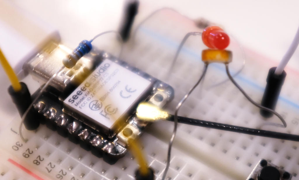
This time it worked! I experimented with the delay and found a delay of 50 ms giving a good visible oscillation of increases and decreases of brightness.
It turned out the program worked in the lab as well, so I could create a video:
You can see that the fade in and out is a bit non-deterministic because of the surrounding light intensity in the lab.
Continue Browsing through the RP2040 Datasheet
Since I didn't finish reading the RP2040 datasheet, I complete this at a later stage.
Peripherals
The Peripherals section contain various components:
I2C
I2C is a protocol for low speed data transfer with a sda (for data), and a scl pin (for the clock). The RP2040 has two identical I2C instances and can be configured to be primary or ....
It can operate in three modes standard mode , fast mode and fast mode plus and cannot operate in high-speed mode and ultra-fast speed mode . Typical usage of high speed modes are devices such as LCD displays, and high bit count ADCs, and high capacity EEPROMs.
ADC and TS
TS stands for Temperature Sensor . The ADC has a resolution of 12 bits with a sample rate of 500 ksps. It has 4 inputs on pins and one input decicated to the temperature sensor. The ADC can generate interrupts for a predefined level and it is possible to have the DMA engine fetch ADC samples.
I should have read this earlier, but it is now quite clear that the ADC cannot take input voltage higher than the voltage it runs on: "The maximum ADC input voltage is determined by the digital IO supply voltage (OIVDD), not the ADC supply voltage (ADC_AVDD)." The datasheet also states: "Voltages greater than IOVDD will result in leakage currents through the ESD protection diodes.". This is most likely exactly what I experienced in .
The temperature sensor is attached to the fifth ADC channel and the datasheet provides a formula for approximating the temperature. There is a note that the temperature sensor is very sensitive to errors in the reference voltage, where a 1% change in the reference voltage can cause a 4 degree temperature approximation.
Reset Control
This ccomponents controls how to reset the processor.
Power on state machine
This state machine describes the sequence in which the microcontroller starts and checks for the peripherals to be done initializing. It controls and checks a set of registers. The datasheet describes in great detail how the boot sequence happens.
System Control
The system control unit is a set of registers for controlling the microprocessor. For example, it is possible to control the timers, memory protection, low power modes, and interrupts.
System Info
The system info unit contains a couple of registers such as the chip ID and the git hash of the chip source.
Watchdog
This unit consists of a timer that counts down and if it reaches zero, it will reboot the microcontroller. This functionality is typically used to debug problems or overcome hardware problems. For example, as soon as a microcontroller is in an infinite loop and a watchdog has been enabled, the watchdog will count down to zero and reboot. To prevent this, you can update the watchdog manually.
Interestingly enough, it appears that the watchdog itself has a hardware issue. The datasheet states: "Due to a logic error, the watchdog counter is decremented twice per tick. Which means the programmer needs to program double the intended count down value."
PIO
PIO stands for "Programmable Input Output" and this piece of logic provides a "versatile hardware interface" that "can support a variety of IO standards". For example, I2C, 3 pin I2S, SDIO, SPI, UART, DPI, VGA. There are two of such blocks and each block has "four state machines that can independently execute sequential programs to manipulate GPIOs and transfer data". So, it kind of a computer that is "highly specialized for IO". The state machine has DMA as well.
These state machines look like cores of a normal processor and they appear to be very high performance. There are PIO programs available for UART, SPI, and I2C, but the PIO can be programmed directly as well and become very flexible.
The instruction set is very simple with only 9 assembly instructions such
as
JMP
,
WAIT
,
PUSH
,
IRQ
, and
SET
. There
is an assembler
pioasm
included in the SDK so programs can be
written by yourself. The datasheet has various examples and there are even
more in the SDK.
DMA
The microcontroller has a DMA engine available to get load off the processor. This is useful for bulk data transfers.
Bus Fabric
The bus fabric connects all the components, so the two cores with a DMA engine to the memory and other units. This section that discusses the bus fabric has quite some detail about the physical connections, for example it explains the layout of the crossbars and there are also many registers for performance debugging.
Core Supply Regulator
The RP2040 has a built in voltage regulator that allows the chip to be powered between 1.8 and 3.3 V. The datasheet states that you can use the voltage regulator for other purposes if you deliver the power in a different way.
USB
The microcontroller has a USB 2.0 controller. It can be run in host mode and in device mode.
The Processor Subsystem
This component is not named in the graphic above, but I think the section "Processor Subsystem" fits best.
The Processors Cores
There are two Arm Cortex-M0+ cores. The processor has all the standard Arm peripherals and the RP2040 adds to that (as we have already discussed).
Interrupts
ARM processors have something that is called NVIC (Nested Vector Interrupt Controller). This unit priorities interrupts and nested stands for the fact that interrupts can get interrupted themselves and vector stands for the table that dispatches an interrupt to a handler function. Each core has an NVIC and GPIO can interrupt the processor as well.
Tasks
Fab Academy
- Compare the performance and development workflows for other architectures.
- Browse through the datasheet for your microcontroller.
- Program a microcontroller to interact and communicate.
- Document what you learned from browsing through the microcontroller datasheet.
- Describe the programming processes you used.
- Include the source code.
Personal
- Make uLisp work.
- Use the microcontrollers without Arduino.