11. Input Devices
This week I started to work on input devices by adding an input sensor to my second micro-controller PCB (which I am planning to fabricate) instead of using back the one that I did during the electronic production week. As for the group assignment, we are going to try and measure an input sensor’s analog levels and digital signals.
You can access the group assignment HERE.
Input Device - LM386 Sound Sensor
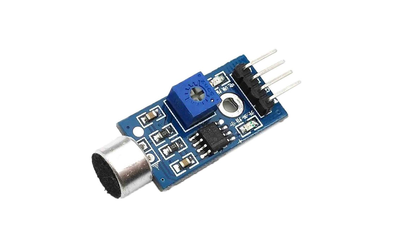
This week assignment, I will be using a Sound Sensor as my input device since I will using them for my final project. Below is an image of sound sensor that I am using.
Likewise to what I have done for output devices and embedded programming, I will start to run a simple program for the sound sensor to test if the sound sensor is working. Below is the program code and wiring for testing the sound sensor and in my case, I am using an Arduino UNO and a RED LED for the testing.
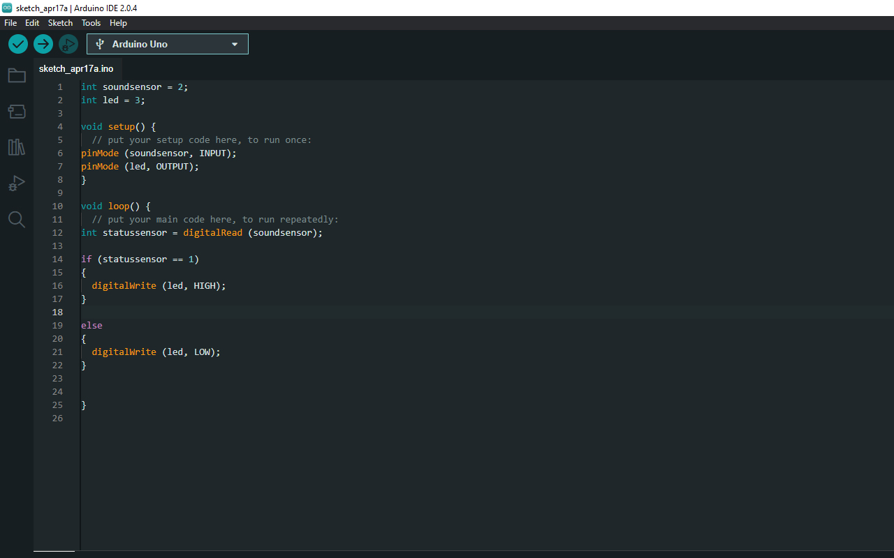
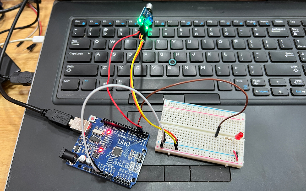
Next, I uploaded the code to test it out if the LED blinks according to the rhythm.
You may download the code HERE.
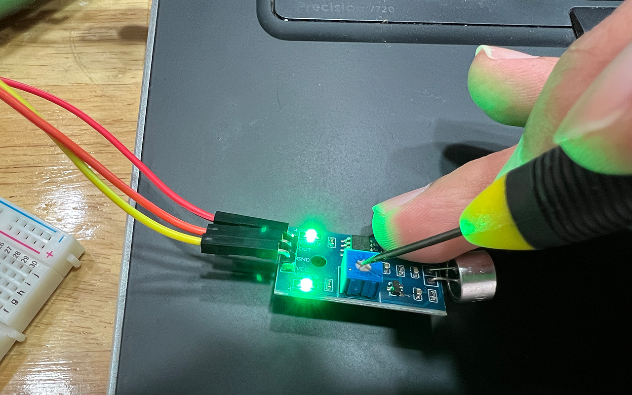
It was a success in running the code and I could actually adjust the sensitivity of the sensor by using a screwdriver to adjust the on-board potentiometer.
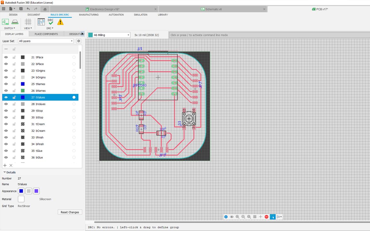
After testing the code, I then proceed to start creating my second PCB that will be link to a (Sound Sensor) and a (LED). I began to redo the PCB using Autodesk Fusion 360/Eagle Electronic Design base on my previous PCB schematic with rectification. As mention earlier, my first PCB was not really done well and I have to do some handyman work to make sure it works. Therefore, I want to take this opportunity to recreate a better PCB. Below is a screenshot of my second PCB design.
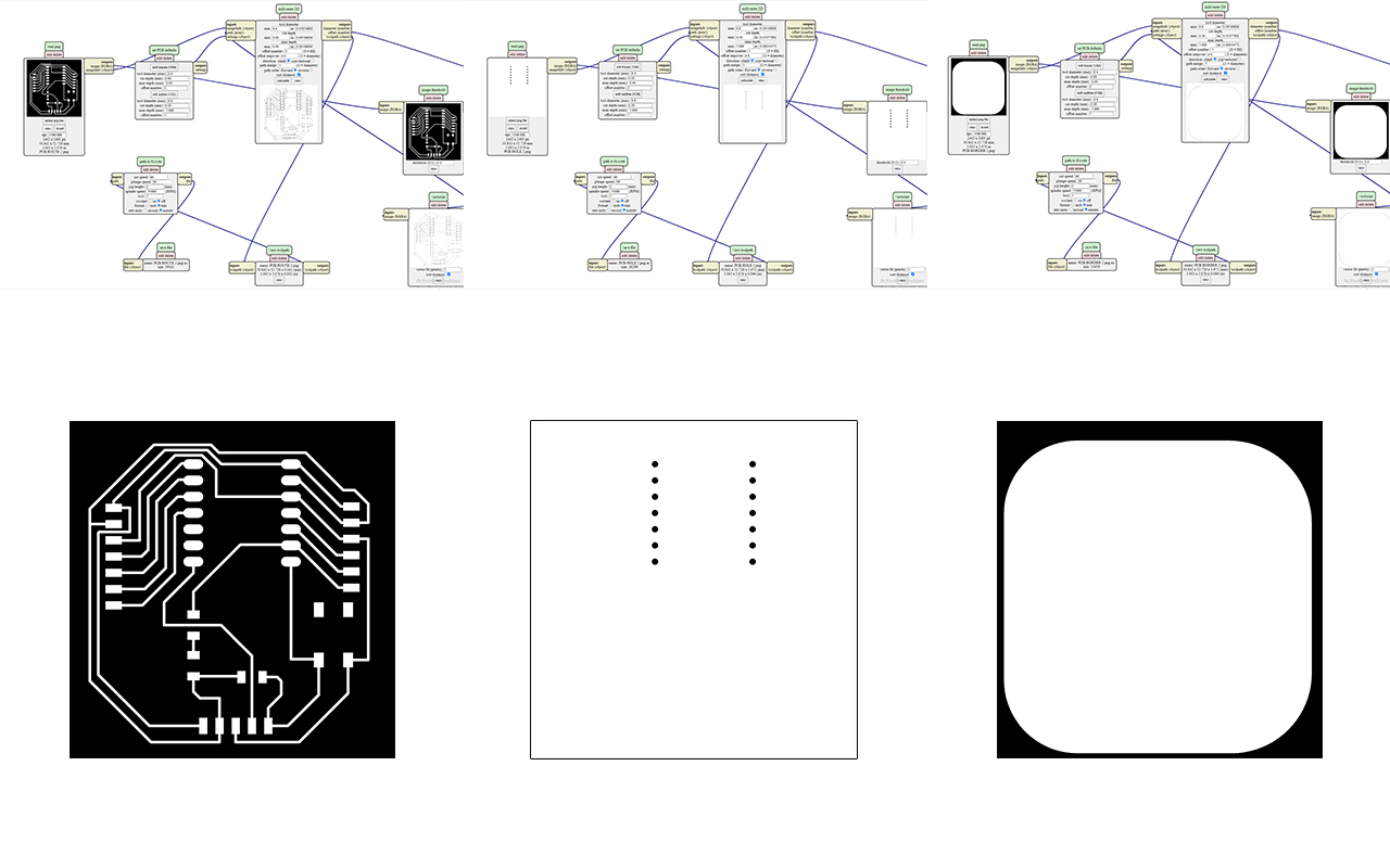
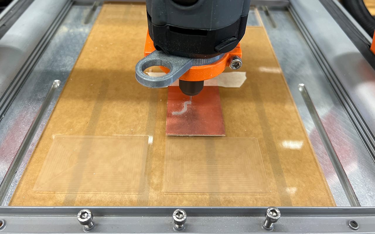
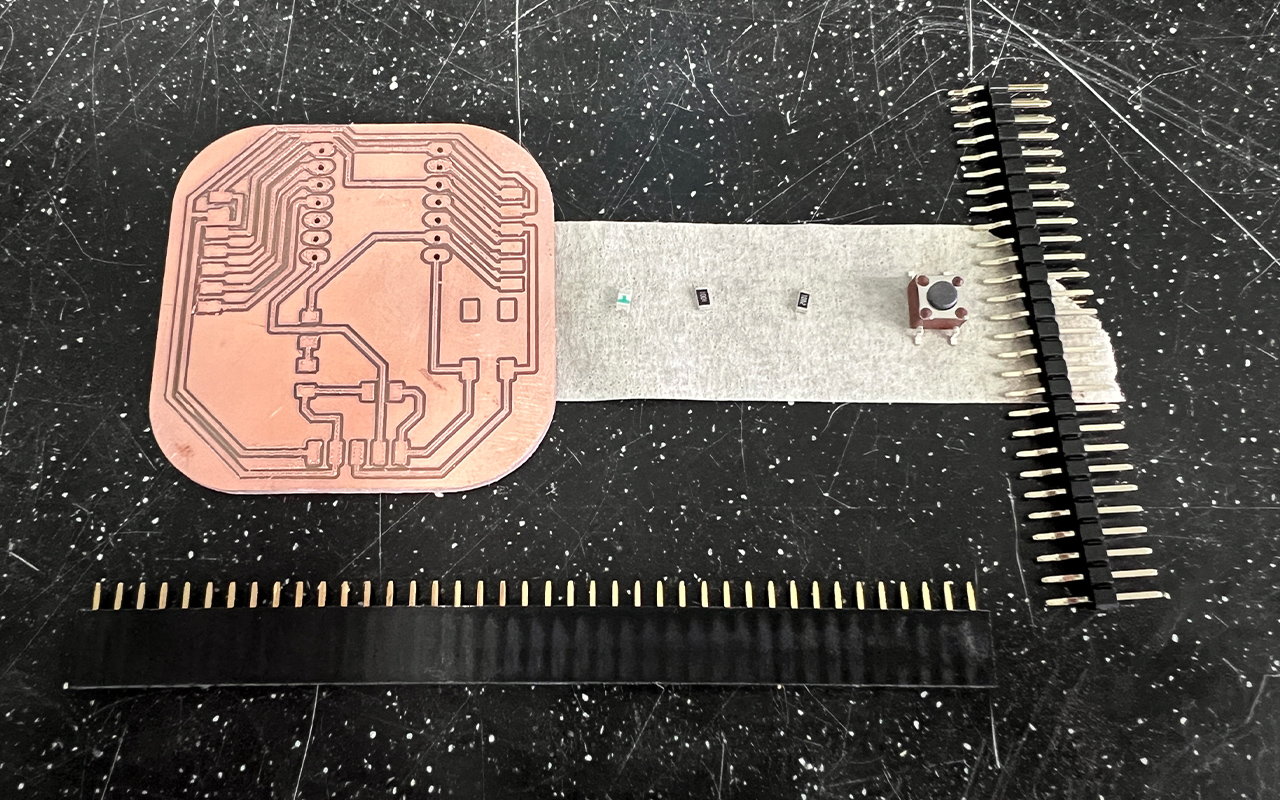
After creating the PCB design and export them in PNG format, I uses the MODs program again to generate the G-Code and send it for milling.
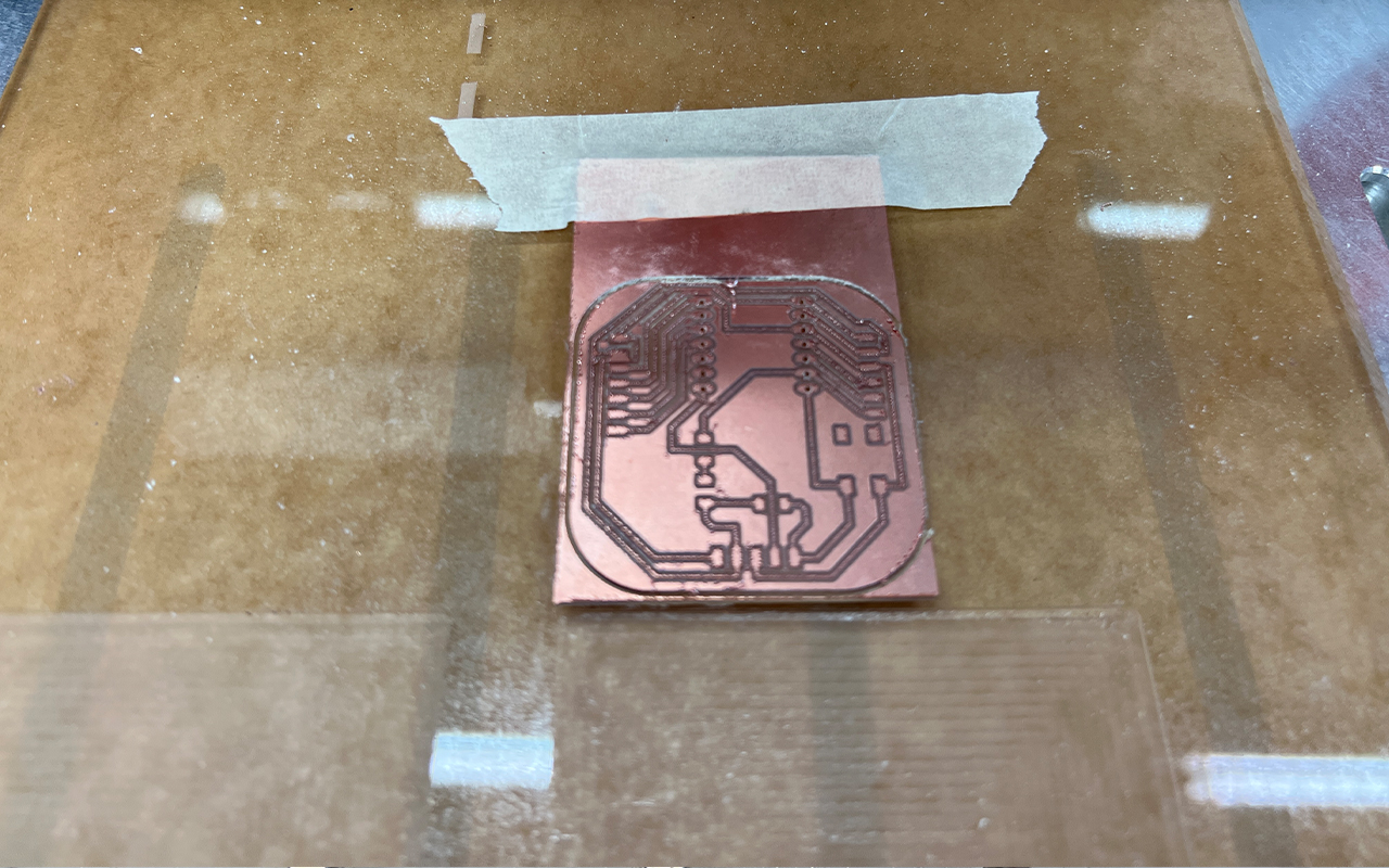
After the milling is done, I then went to prepare all the components such as the LED, Resistors, Buttons and Header Pins etc.
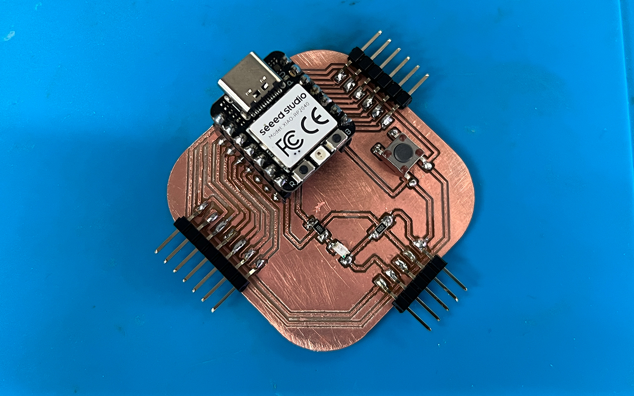
Next will be the most tedious task of all, to solder the components onto the PCB. Again it took me half a day just to get all the components soldered as seen in the image below. So far so good in terms of the overall outlook but yet to test it out.
I then proceed to test my new PCB and guess what?, it FAIL! It was so frustrating and now I have to troubleshoot again to see what went wrong. This time round, I could not identify the issue of my PCB and why does it not work! As time is getting late, I then decided to use back my first PCB (which was rectifed) to test out the sound sensor and LED for this week assignment.
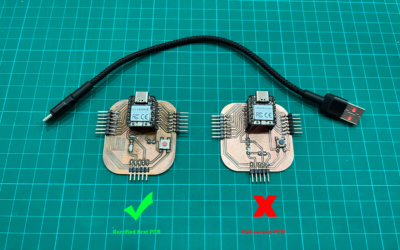
After loading back the same code that I have used earlier on with Arduino and amended the codes according to the Xiao RP2040 Digital Pins, my input device - sound sensor and output device - LED works! The codes and my PCB with Xiao RP2040 micro-controller function well as per my earlier test on Arduino, which is a positive news for me. What is left for me to do is to try and rectify my second PCB and hopefully, I can find the problems to it. Below is a video that shows how my input sound sensor as well as my output LED device reacts to the beats and rhythm of the music:
Reflection
It was a hectic week for me as I was oversea for more than a week and I am unable to work on my assignement until the 17th of April. I only have 2 to 3 days to finish both my group and individual assignement not to mention that I still have my own work and teaching to do. But luckily, it was not that stressful as this week assignment is quite similar to the Output Devices assignment, so most of the task and things were pretty much manageble except that my second PCB design fail again! It was not easy especially for the soldering portion which took a toll out of me. I will probably need to spend abit more time to improve my soldering skills when I have the time.