7. Computer Controlled Machining
This week I started to work on computer controlled machining and learn how to use a 3-axis CNC milling machine. As for the group assignment, we will need to go through our lab safety training and to do a test run of our CNC milling machine. Our group members have work together on testing the alignment, fixturing, speeds, feeds and toopaths of our CNC milling machine using V-Carve Pro with the guidance of our local Instructor.
You can access the group assignment HERE.
CNC Milling with V-Carve Pro & EAS Versatil 2500
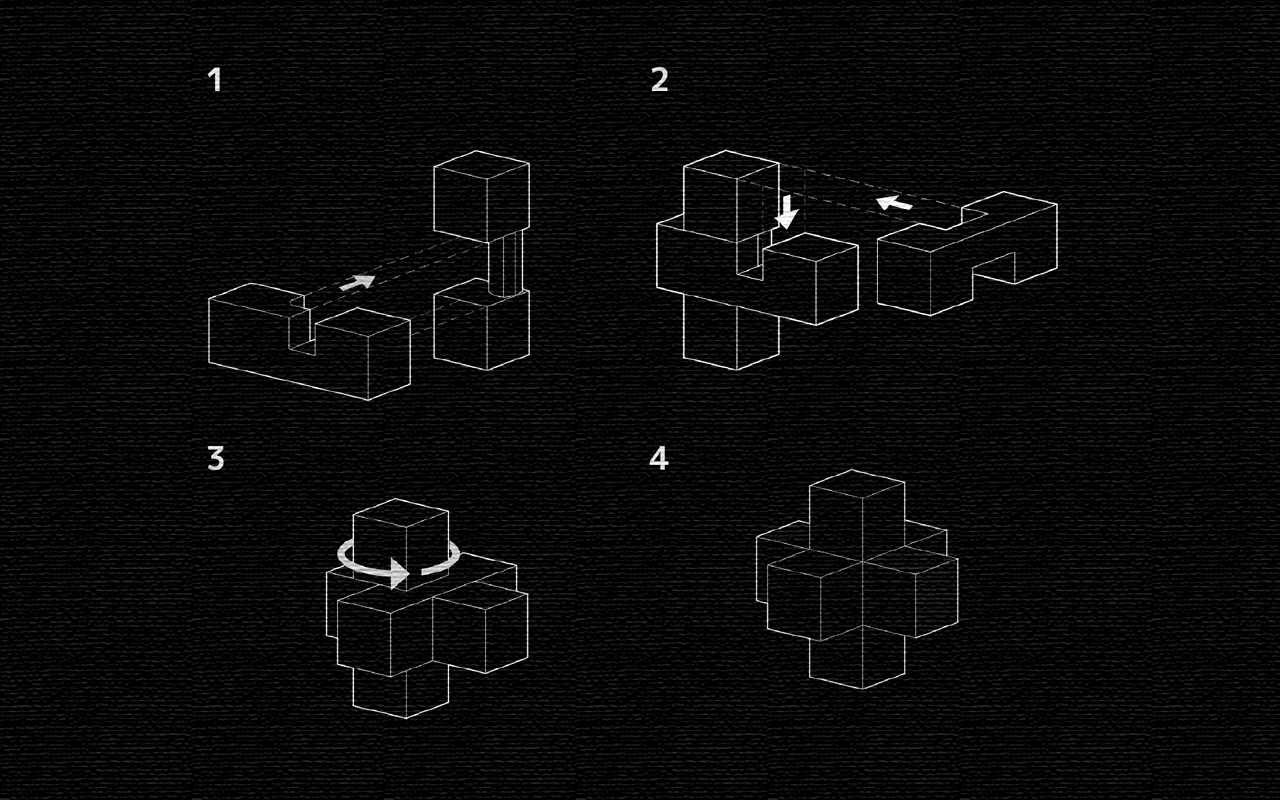
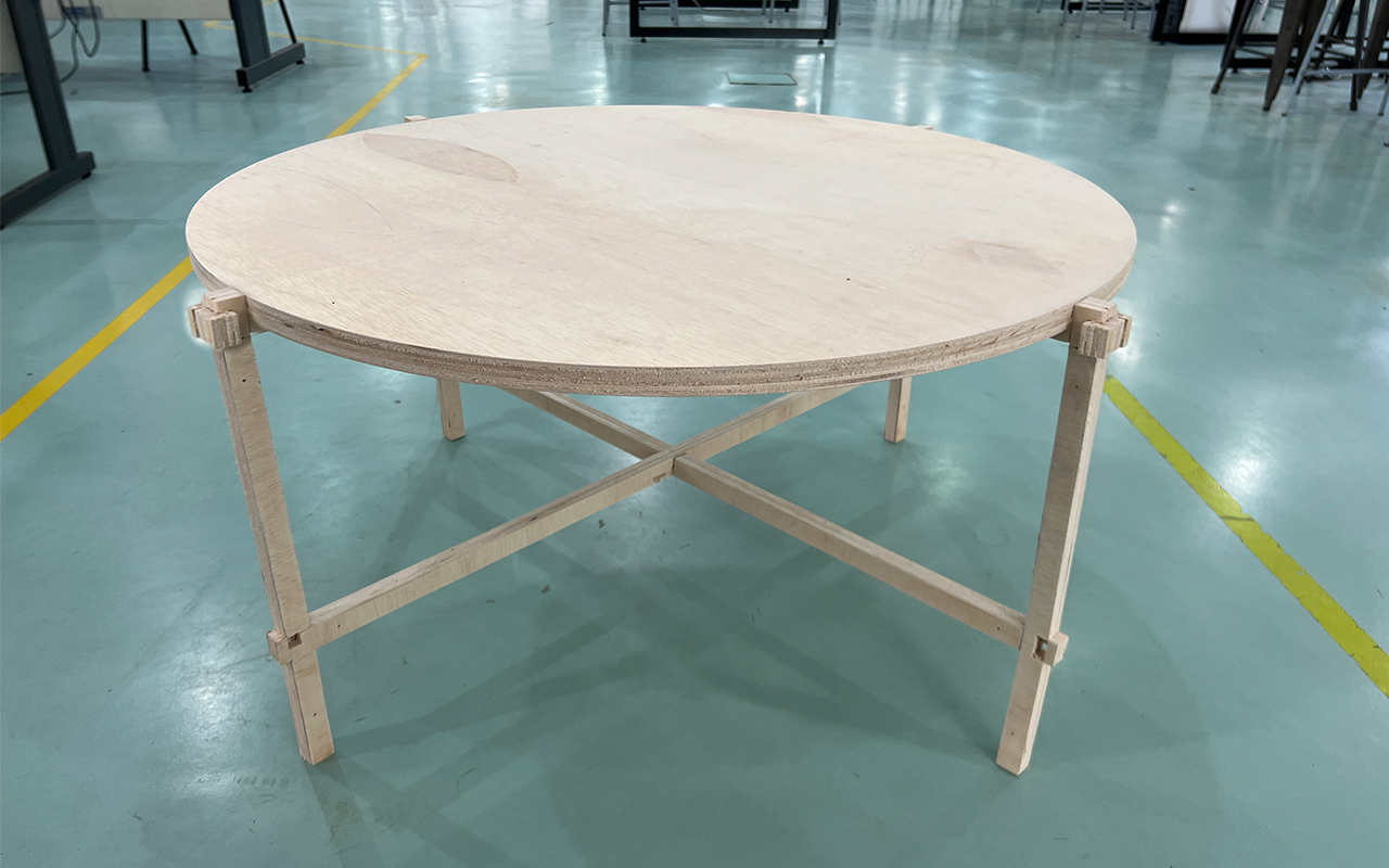
For this week assignment, we are suppose to design, mill & assemble something big (meter-scale) just from using the CNC milling machine. I have an idea to make a furniture, a coffee table using some wooden planks that we have salvaged during the renovation of our Library outdoor area. Also, while i was browsing the internet to look for inspiration of my coffee table, I came across this wooden joint system called Chidori. It is a traditional wood joint technique developed from the joint system of old Japanese toys. I find this Chidori joint very fascinating as it does not employs any screws or fixture to assemble! It is a joint system purely base on traditional craftsmenship, something I like very much as a designer.
But before I begin, I would like to share a problem that I face for the CNC milling of my coffee table. As mention, I am trying to salvage some old planks and to use them as my materials for the coffee table.
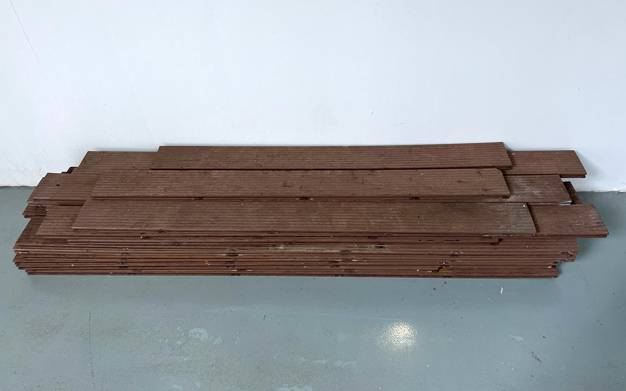
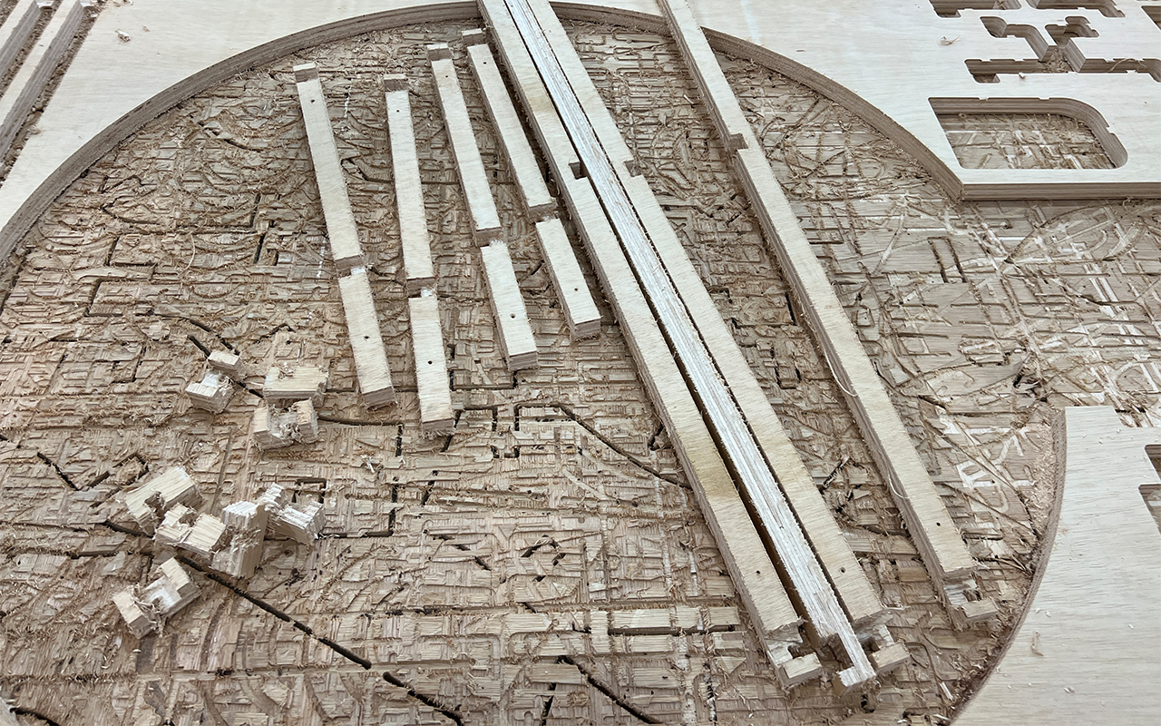
To cut the story short, I went through the entire CNC process (which i will share later on) and manage to get all the parts done which was quite good initially. The finishing was excellent and smooth. However, when I was trying to do some post-processing sanding to the parts, they broke off like a Kit-Kat chocolate bar. That was really disappointing as I thought I could make good use of those old wooden planks to do something nice and useful but somehow the renovation and replacement of these old wooden planks are there for a reason because these planks are already rotting and decaying within itself. They do not possess the strength anymore to be use for any structure. So, in other words, I will need to redo the entire project with another material - Plywood (which is not ideal).
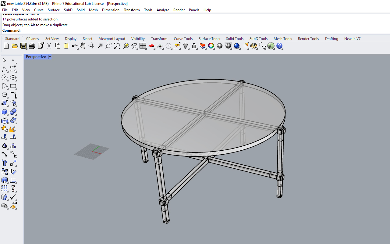
So let us continue with the process of my CNC milling journey: Firstly, I will need to have my design ready therefore, I started to create my coffee table in Rhino 3D with references from Chidori joint system. Prior to this, I have also done a sample model of the Chidori joint system so as to have a better idea and understanding on how the joint system works. I then export the sample model and have it 3D printed to have a feel on the assembly process and to my surprise it was rather easy!
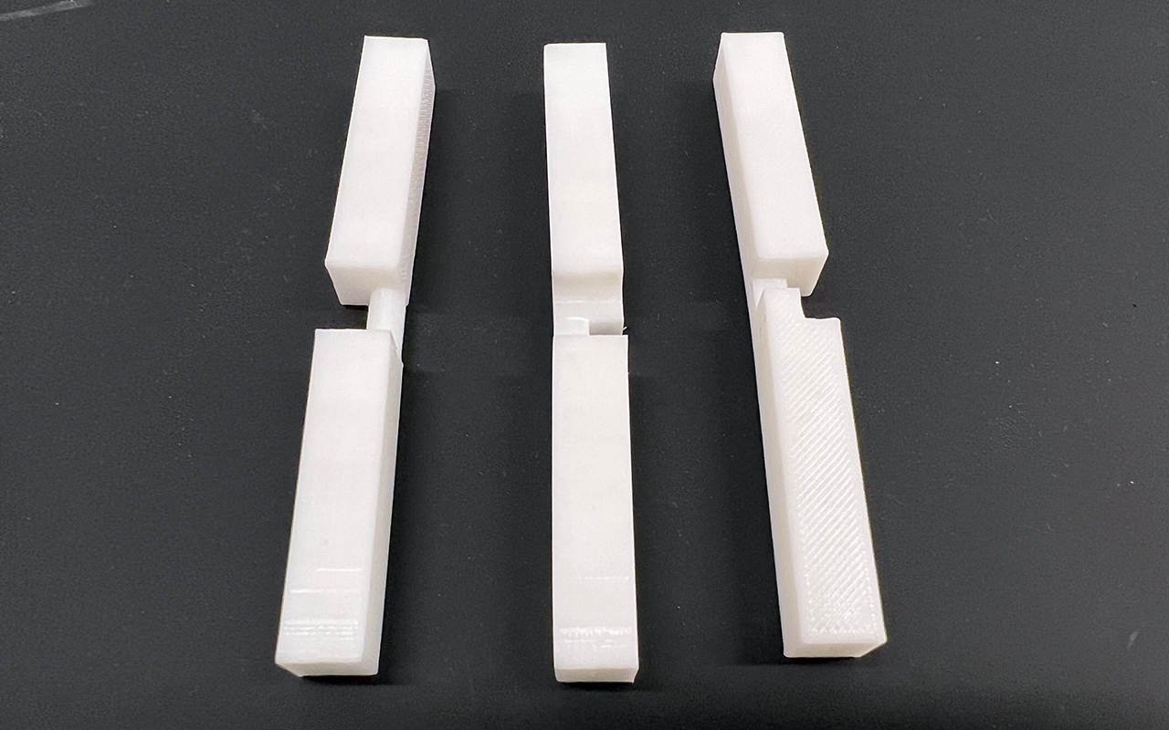
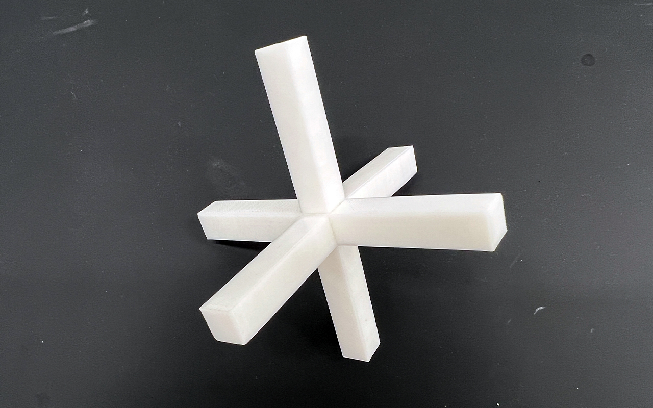
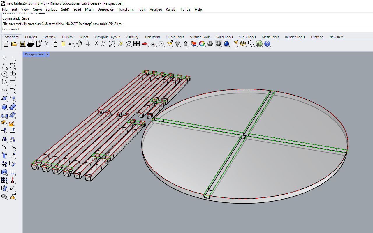
After 3d printing the model sample joinery parts and testing it out to ensure its workability, I then went on to prepare the model files which we will be send to V-Carve Pro to generate the G-codes for CNC milling. As I have experiences in doing CNC milling works before using V-Carve Pro, I am very familiar on its processes and which methods is the best and easiest for me to mill the parts in the shortest time possible. As shown in the image below, there are Green & Red outlines, these outline represents different profile setting that I am going to use for the milling process:
- Green - This is for the Pocket Profile Toolpath, to be use for milling the inner pocket features.
- Red - This is for the 2D Profile Toolpath, to be use for milling the general outline of the parts.
I have also prepare 3D model (in 3dm format) as I have some 3D details which I will then need to use the 3D Roughing & Finishing Profile toolpath to do the job. However, this will be done if I have enough time as there is only 1 large bed CNC milling machine available and I may not have the luxury of time to access the machine as others would need to use the facility as well. Therefore, if I cannot do the 3D Profile Toolpath, I can just do a manual sanding myself with a sanding file.
Next, we will import the 2D Vector file (which I have prepare earlier in Rhino 3D) into V-Carve Pro. Prior to this, we will also need to indicate our Stock Material Size, so in this case, I am working on a 4 x 8 ft x 1 inch thickness plywood hence, my material stock size will be 2440mm in the X axis, 1220mm in the Y axis. and 25.4mm in the Z axis.
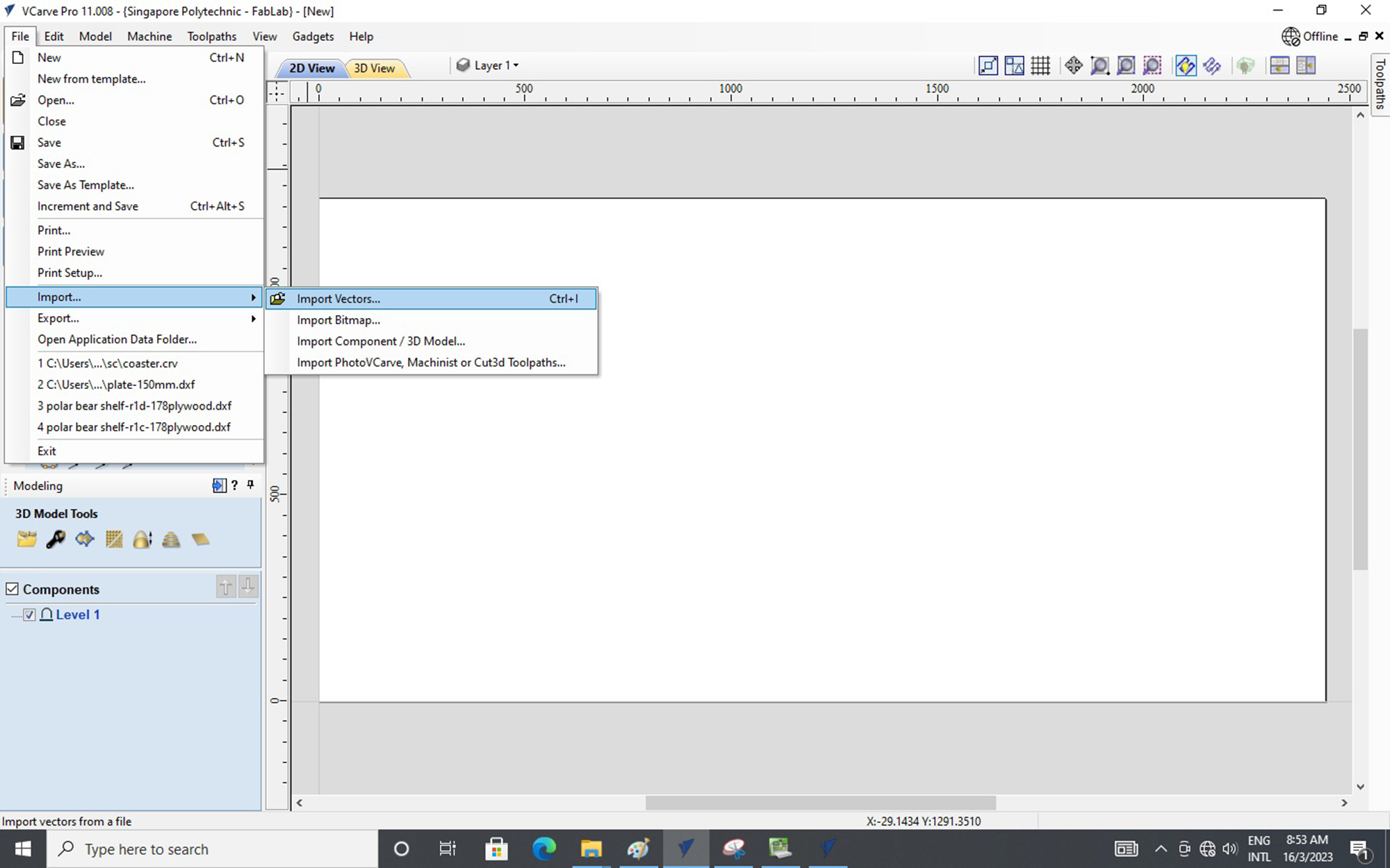
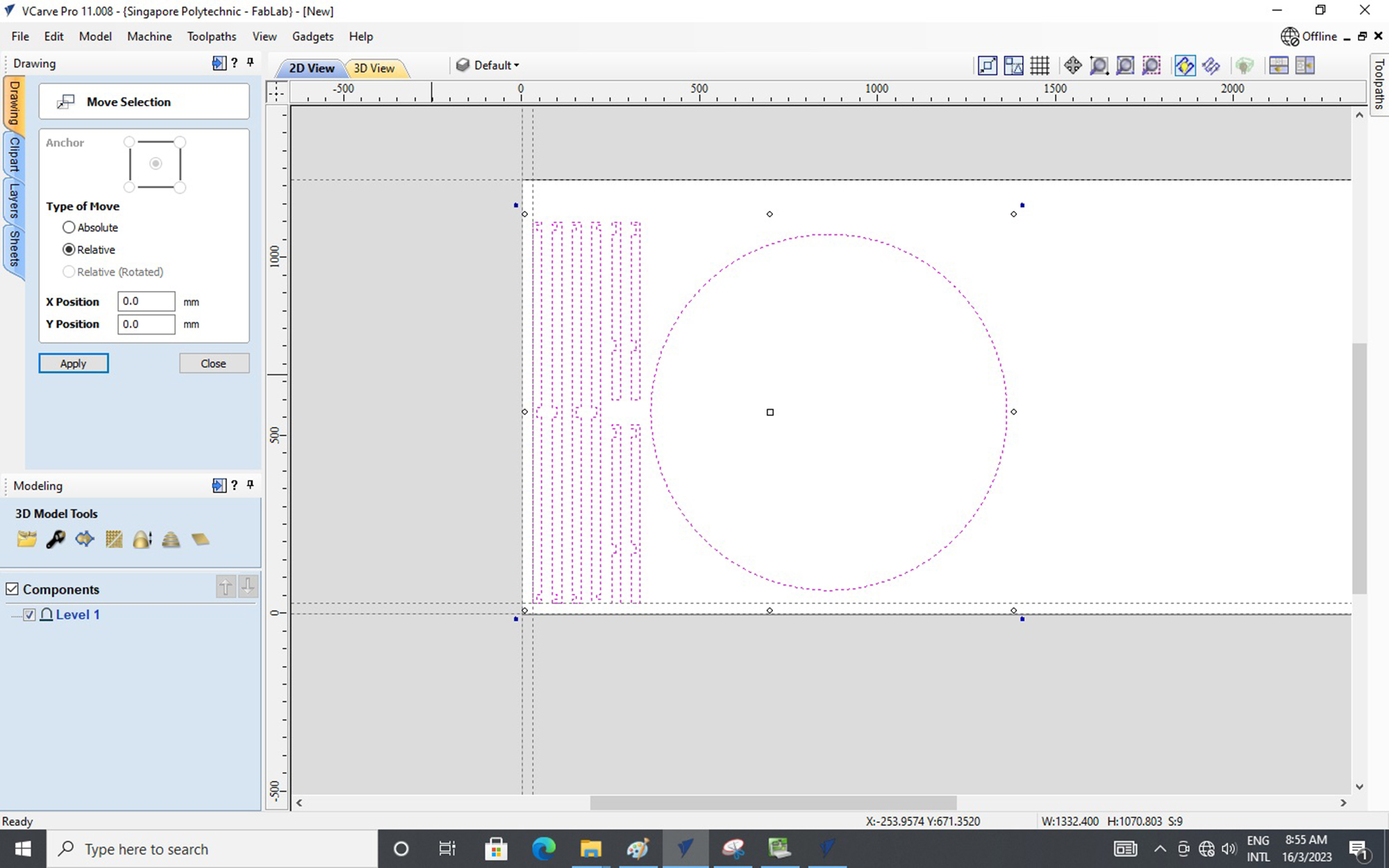
After importing our vector file into V-Carve Pro, we can use the Move Selection tool to shift and move our vector file into the working space (the stock material) and you may also use guidelines to mark references for easy calculation and measurement.
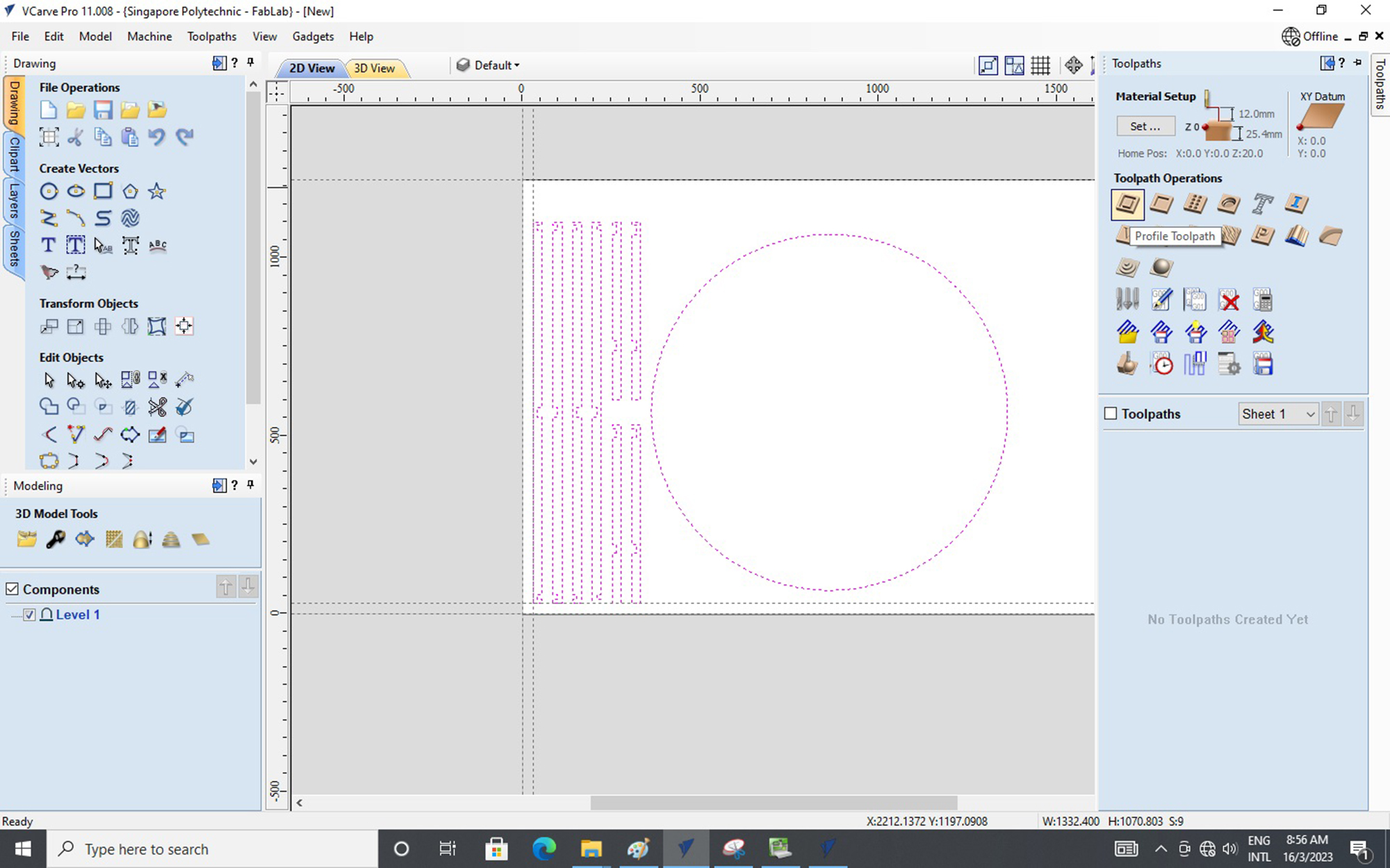
Next, we can go to the Toolpath tab and select the correct toolpath for our job. In this case, we are going to select the Profile Toolpath (2D) to do our outline milling of all the parts.
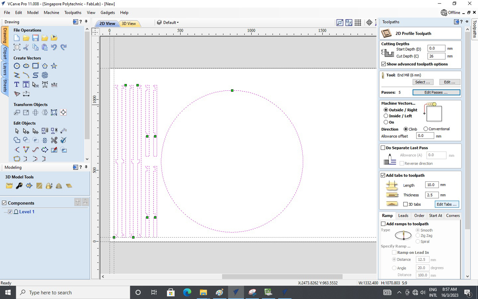
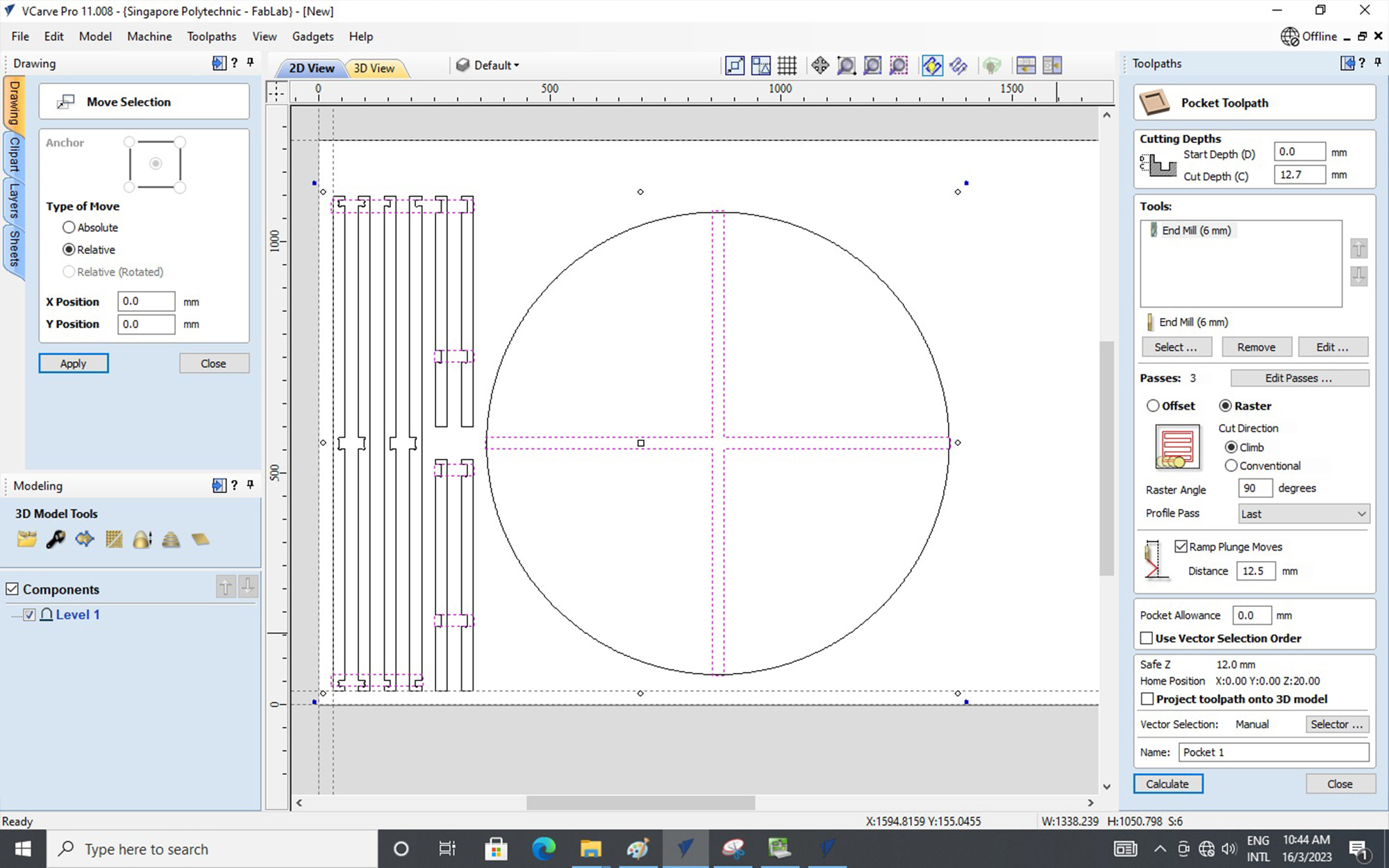
Within the Toolpath tab, we can make adjustment to the parameter settings similar to 3D printing however, some important points to take note of the setting for CNC milling are:
- Start Depth & Cut Depth - This is to indicate where is the milling going to start and the depth that it is milling.
- Selecting Cutting Tool - This is to select the Milling Bits, in this case, we are using the End Mill (6mm) bit.
- Passes - This is to indicate how many times the milling process is going to take to mill the require depth;
(Rule of Thumb is that the milling depth should not be thicker then the diameter of the milling bit.) - Machine Vectors - This is to control the milling path, whether you want it to be Outside or Inside.
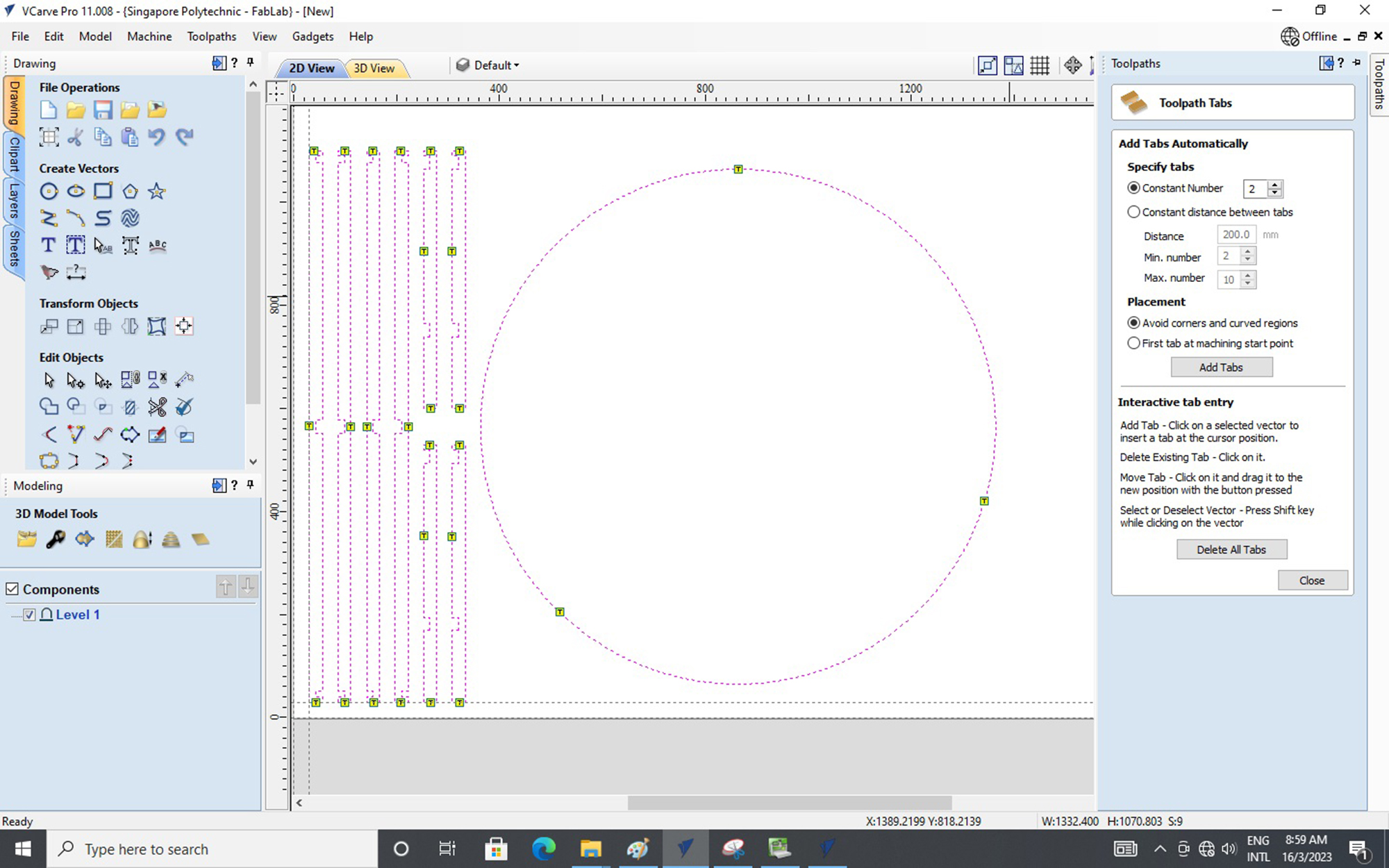
- Tabs to Toolpath - This is to assign Tabs to individual parts so that the parts will not be detach and fly off duing milling;
(This is very useful as Tabs can ensure the accuracy and safety of your parts.) - Ramp & Leads - These are optional features but do have its benefits such as Ramp reduces sudden shock loading on
milling bits by gradually milling in depth while Leads reduces the chance of overheating of the milling bits.
Lets talk abit more on the Tabs as you can assign the tabs to where you want but the Rule of Thumb is that you will need to have a minimum of 3 tabs to ensure stability.
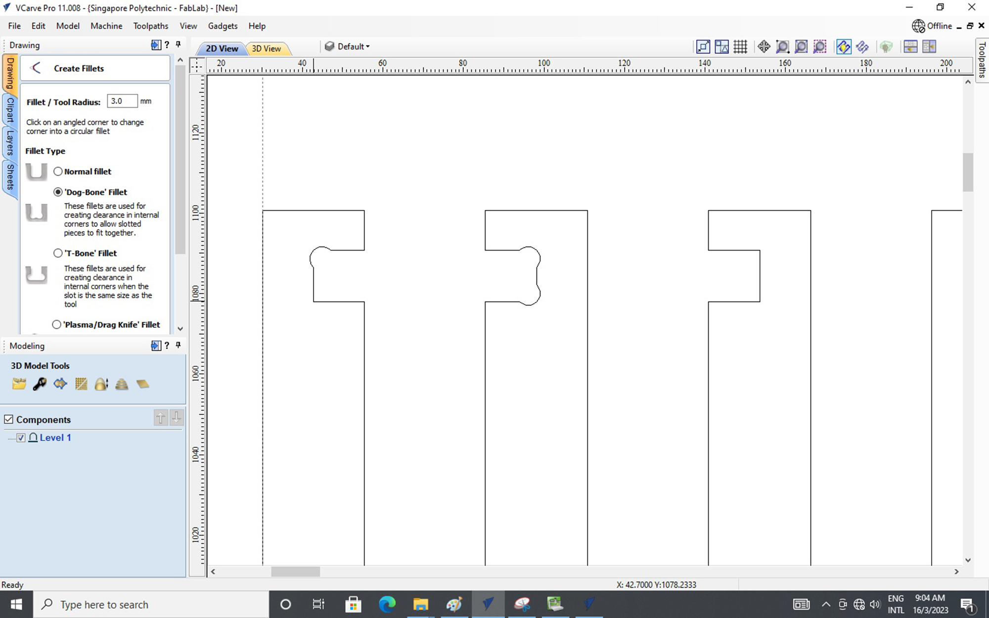
Next, I want to share a useful feature which is Create Fillets - Dog-Bone & T- Bone. These are useful features as we all know that there is a limitation in CNC milling of right-angle feature and usually it will comes with a radius-cut corner so with Dog-Bone & T- Bone Fillets, you will solve the radius-cut corner issue. But of course, it does create some rounded edges to your parts. Some Pros and Cons to take note.
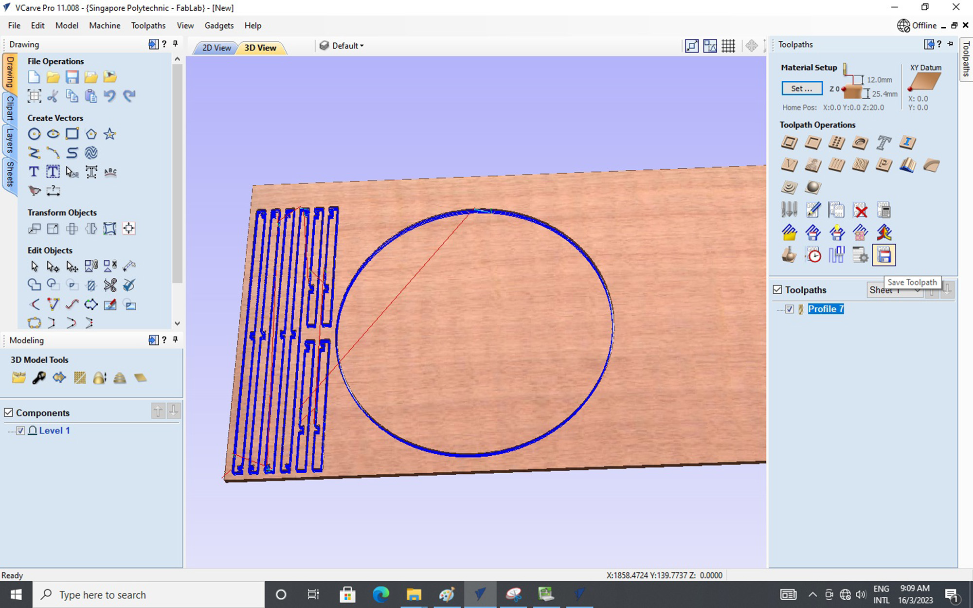
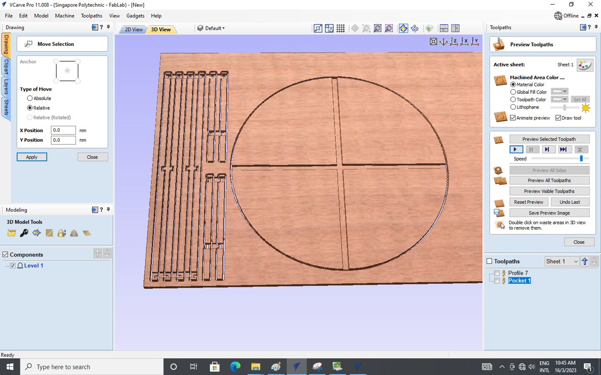
After all the settings are done, you may proceed with the toolpath by pressing the Calculate button. You will then be prompted into a new interface showing a preview of the working path in 3D.
If the preview shows no flaws or issue, we are good to go to save the toolpath into G-Code.
Similarily, We will do the same steps for the milling of the Pocket Profile.
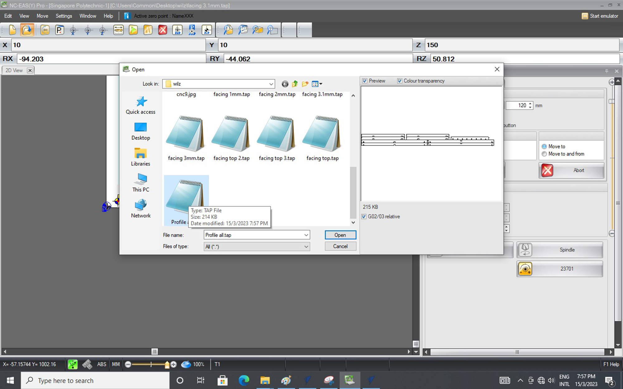
Next, We will launch the NC-EAS(Y) Pro software so that we can open up the G-Code toolpath file to run the CNC milling process.
But before we run the CNC milling process, we will need to do a calibration of the EAS Versatil 2500 CNC milling macine first. The steps to calibrate the machine are as follow:
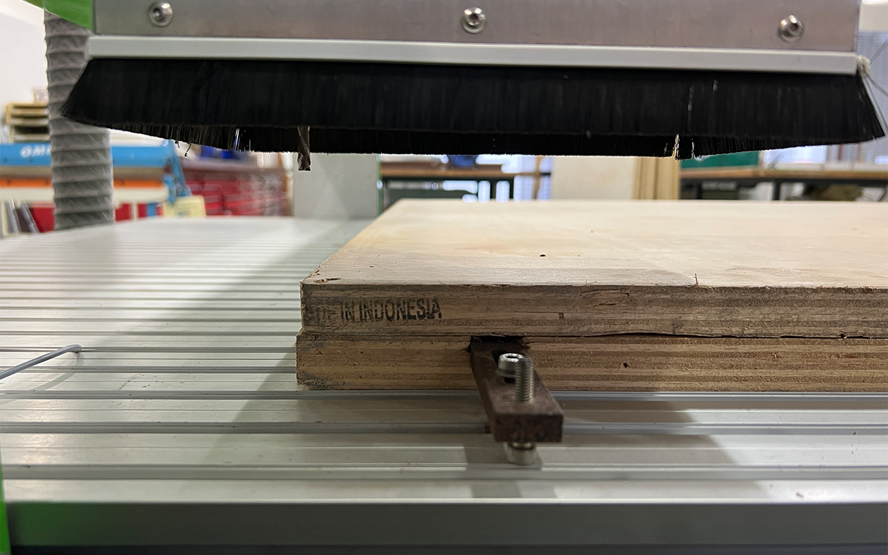
- First we need to place the material on top of the machine and secure it with screws.
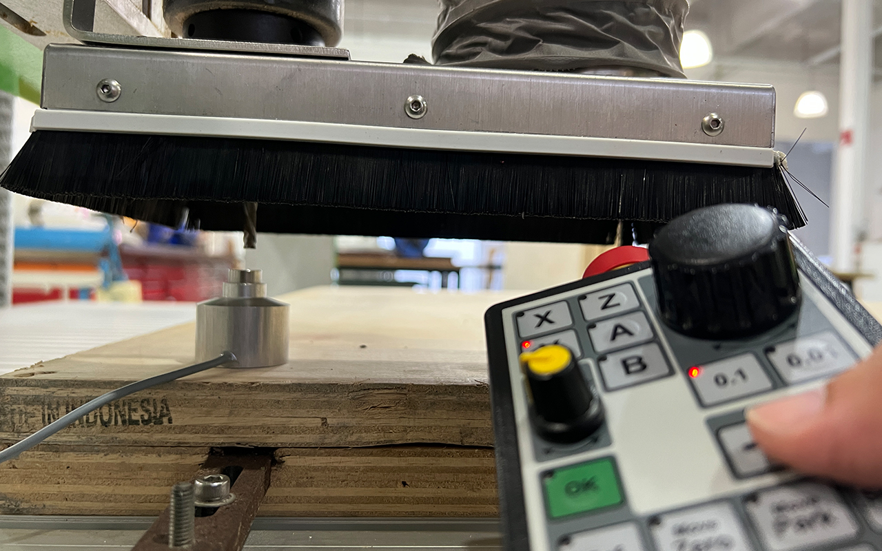
- Next, we will need to ensure that the Tool Sensor is place on top of the material and at the correct place setting.
- Then we do a Z-axis calibration by selecting the Tool Length Measurement button.
- After doing the Z-axis calibration, we will then need to do the X & Y axis calibration too.
- We will adjust the center point of the milling bit to the bottom left hand corner of the material. (Material Reference Point)
- The final step will be to set the X & Y axis by pressing the Set X button follow by OK button, likewise for Y axis.
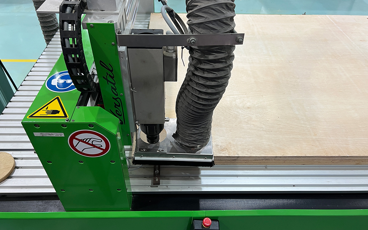
1. Placement of Plywood material on the table top of the EAS Versatil 2500 CNC milling machine.
2. Z-axis calibration using the Tool Sensor.
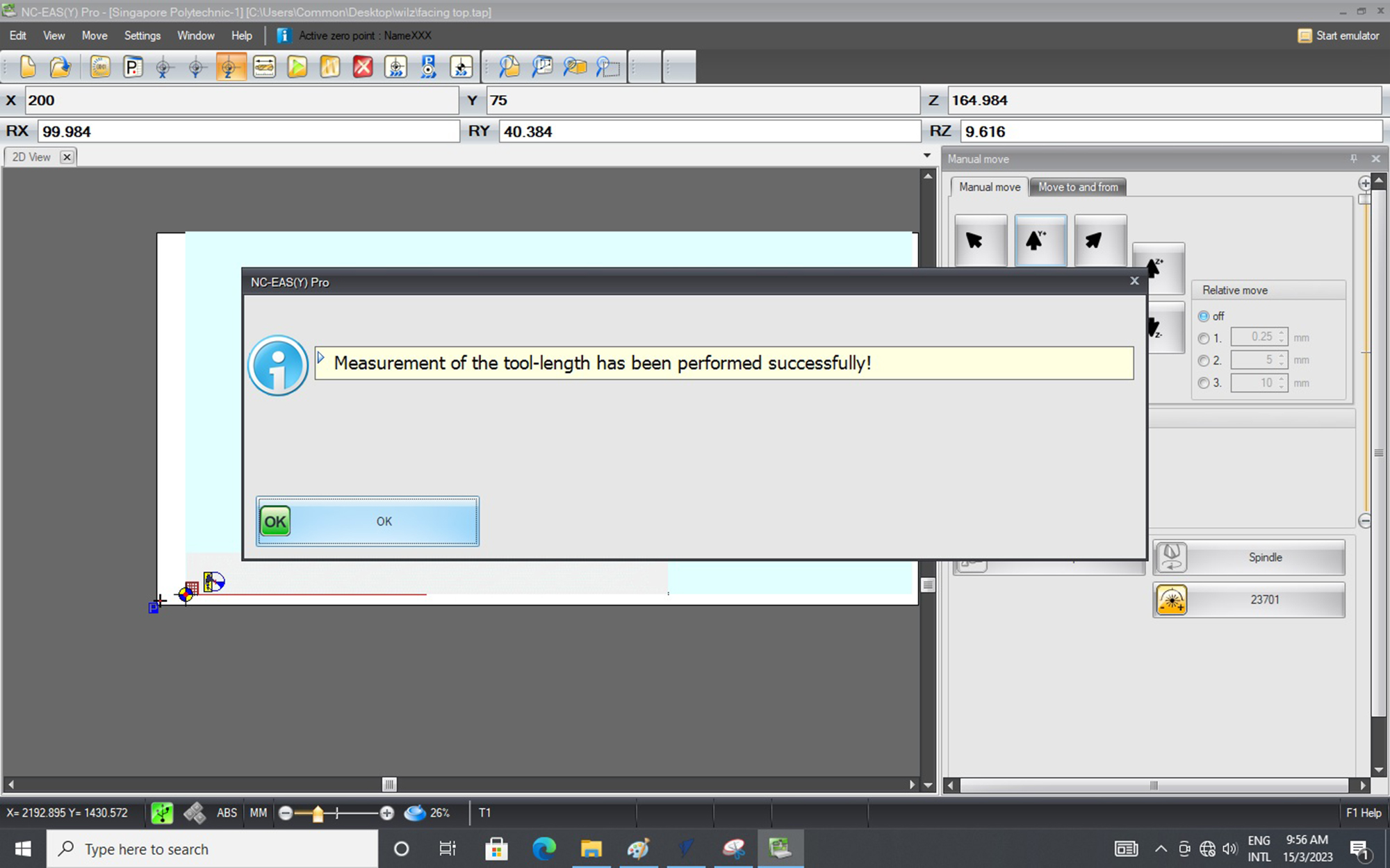
3. Z-axis successfully calibrated using the Tool Sensor.
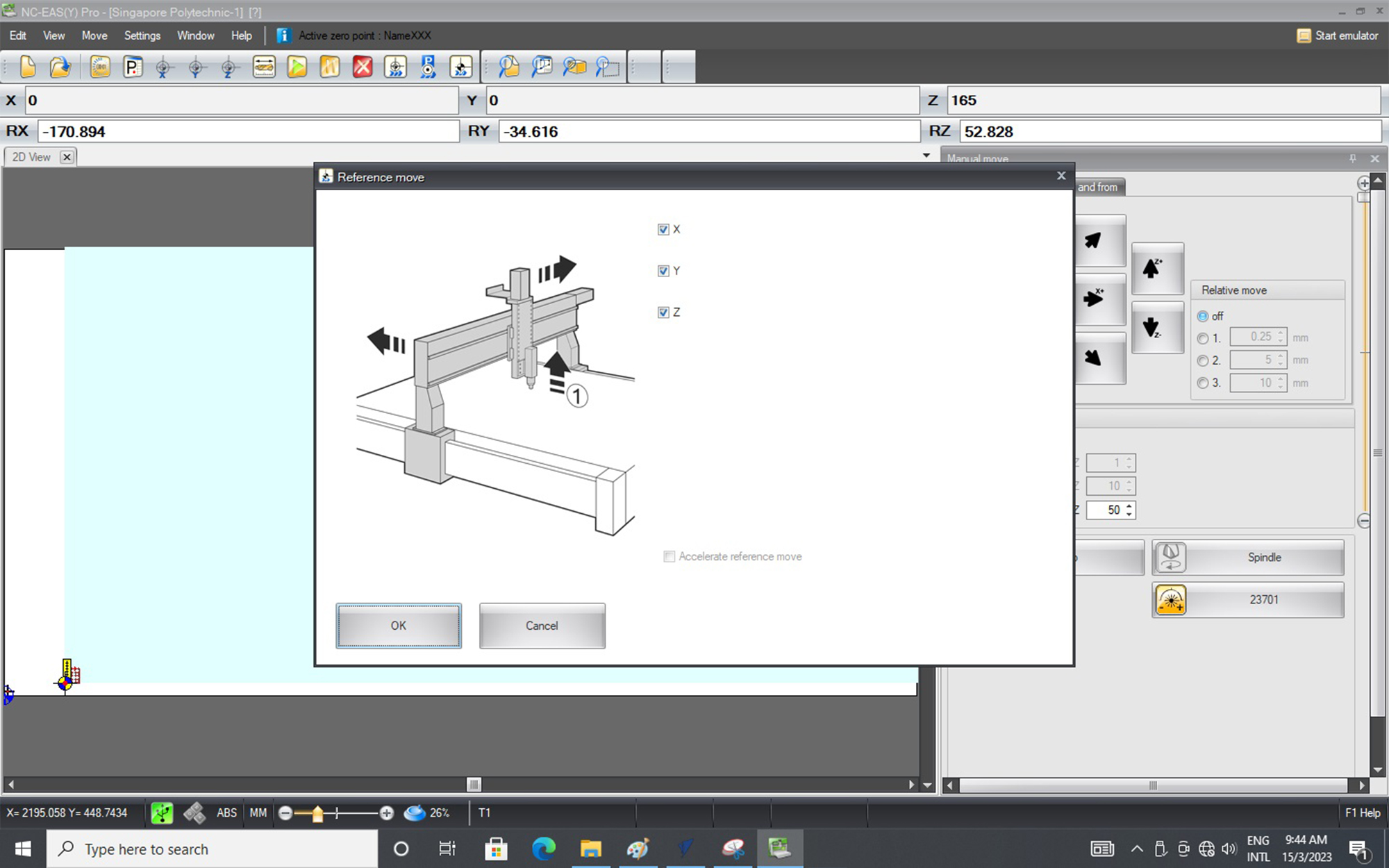
4. X & Y axis manual calibration
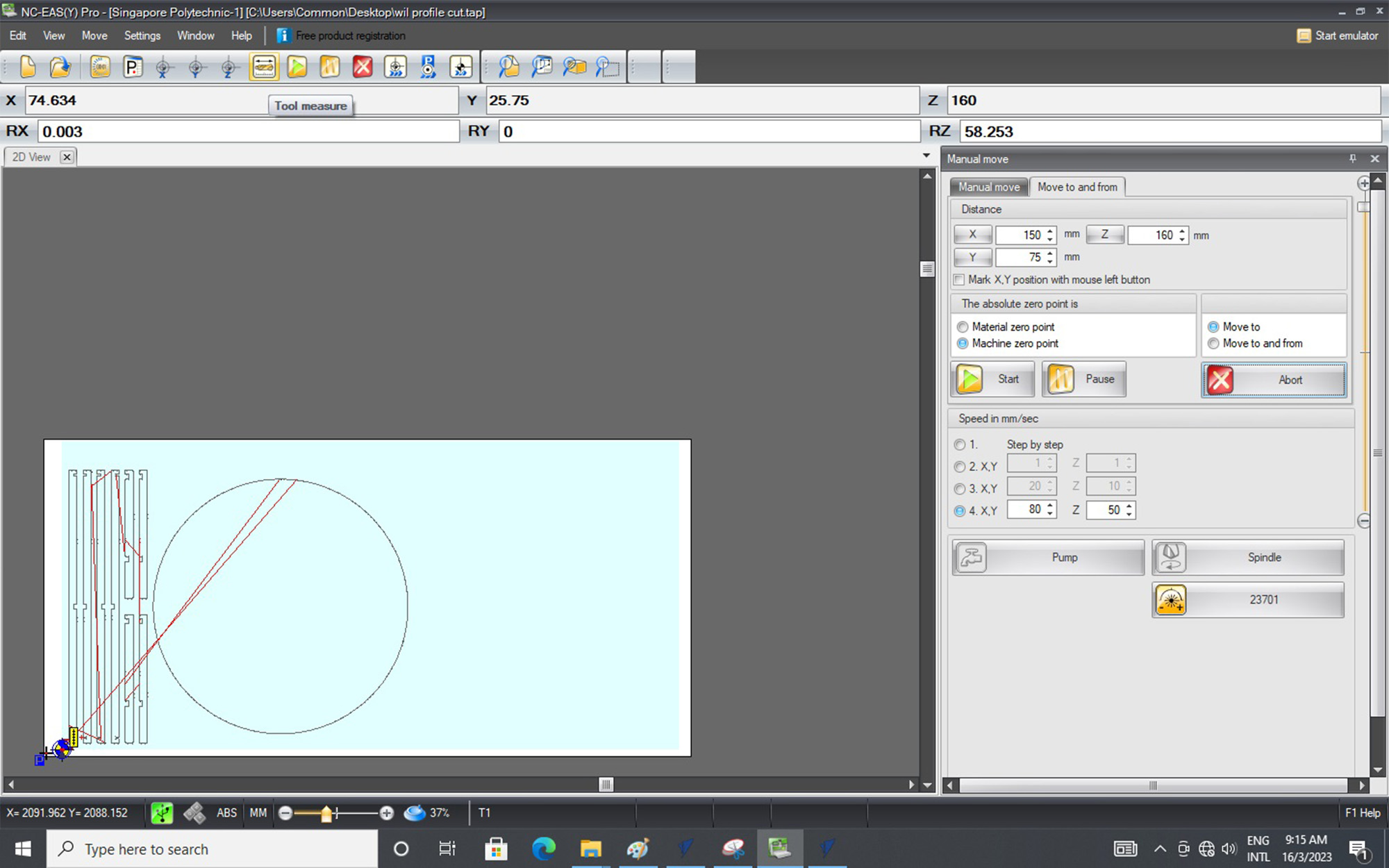
5. X & Y axis successfully calibrated and doing a Reference Move.
6. After all settings are done, we can just select the green Play button to start our CNC milling process!
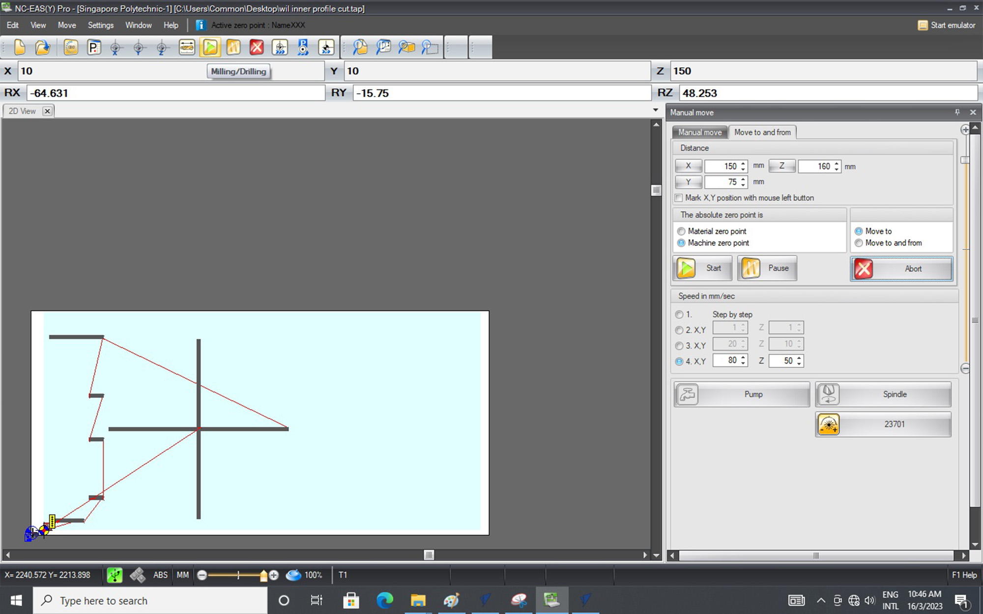
Likewise, we will do the same process to CNC mill the Pocket Profile.
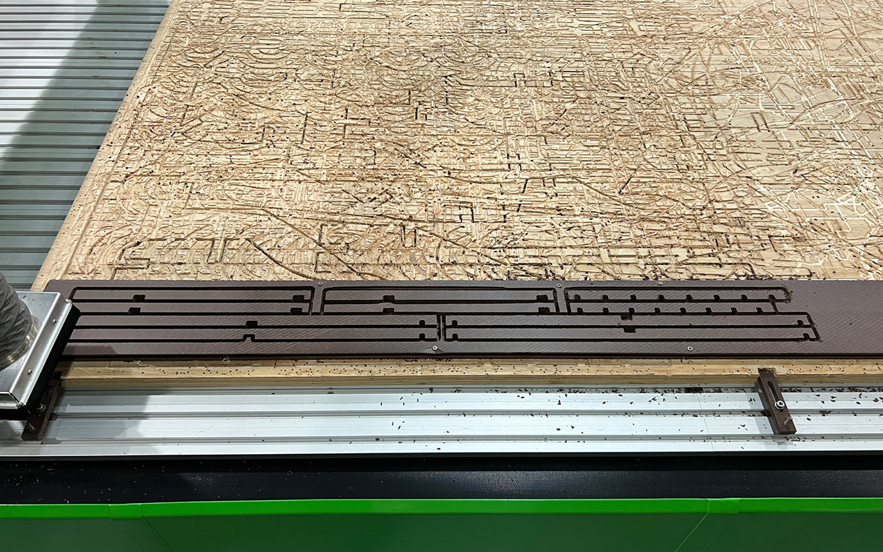
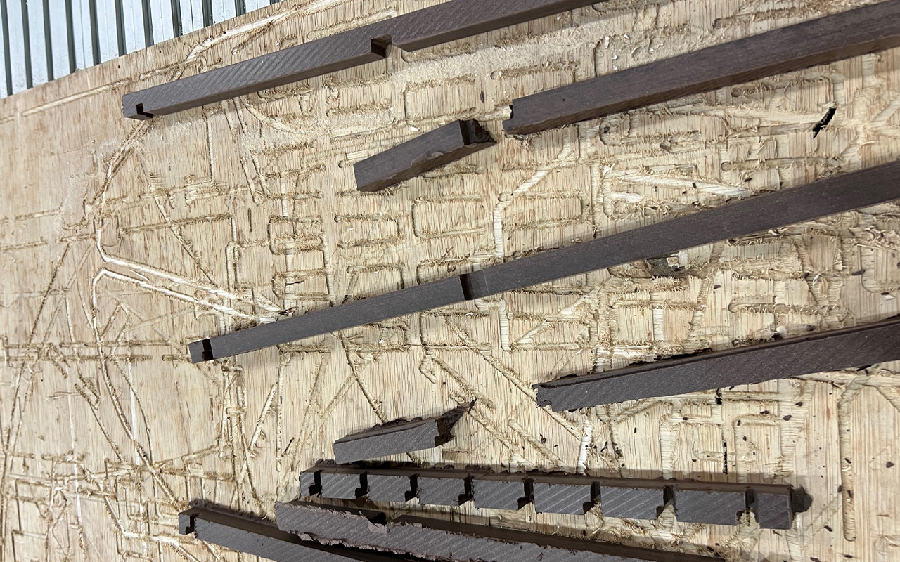
Once the CNC milling process is done, we can use a Chisel to remove the tabs.
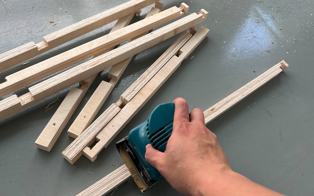
The next step is what I hate the most - Sanding. We will need to use sand paper and portable sander to remove the burrs.
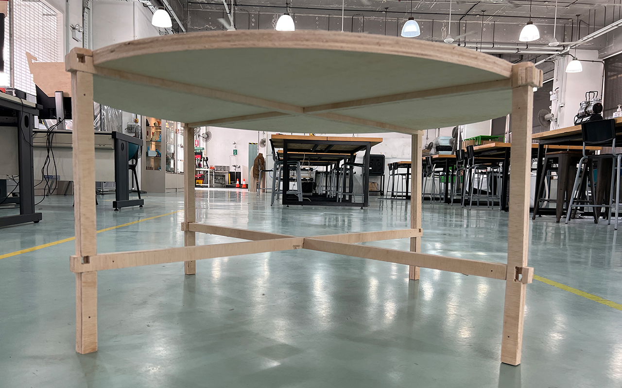
After all the sanding is done, it is time to do the assembling of the coffee table! However, I am now face with another problem because plywood is not a really good material to make the coffee table as it is brittle especially on thin profile, and some of the parts actually broke during the assembling process. Also, some of the parts are unable to be fitted due to accuracy issue. This may be due to the warping of the plywood during cutting that causes some dimensional differences.
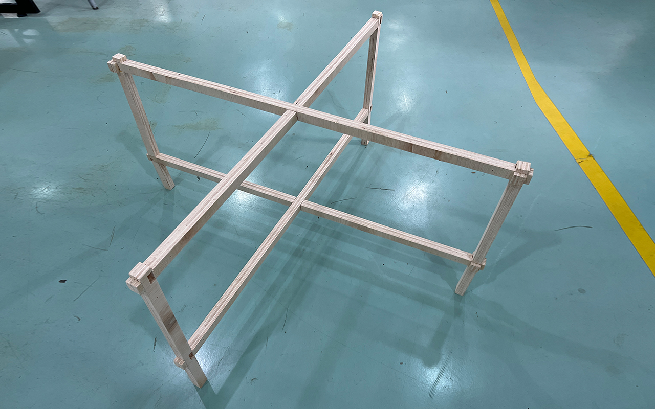
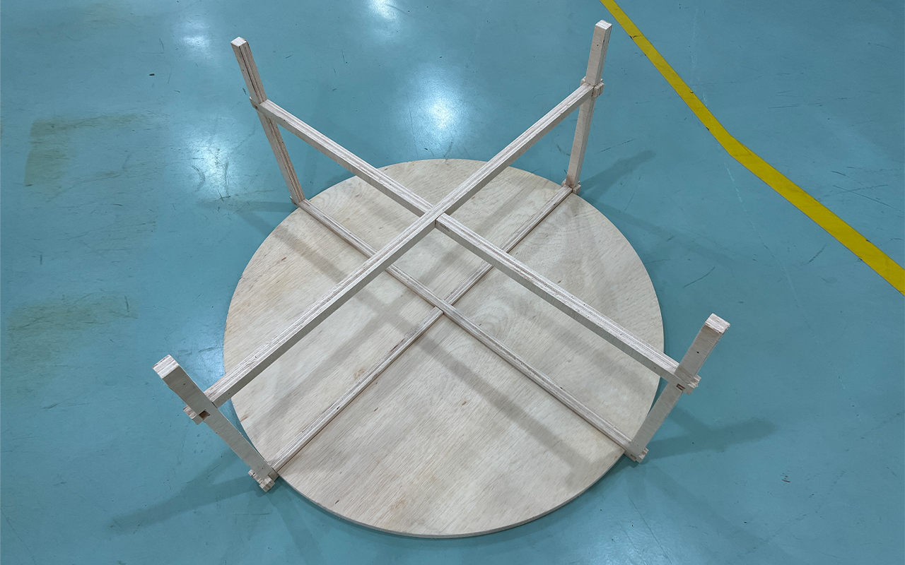
Nonetheless, I try to assemble the coffee table to the best I can and that is how my first attempt of the coffee table design looks like. Overall design looks good but the only disappointment is the material which is kind of a regret.
You may download the 3D model file with the Vectors for CNC HERE.
Below are the setting parameters for the CNC milling of my Coffee Table using V-Carve Pro:
- Cutting Tool - 6mm End Mill
- No. Flutes - 2 Flutes
- Spindle Speed - 12000rpm
- Chip Load - 0.1667mm
- Feed Rate - 4000mm/min
- Plunge Rate - 500mm/min
Actually, the cutting tool (6mm End Mill) is not really the most ideal tool for the CNC milling of plywood as it is an Up-Cut milling bit instead of a Down-Cut milling bit. The reason of using the Up-Cut milling bit is due to the fact that our lab does not have a Down-Cut milling bit of the require diameter so we have to make do with what we have at the moment. I have attached a table of references in terms of the ideal kind of milling bit that is good for its respective application:
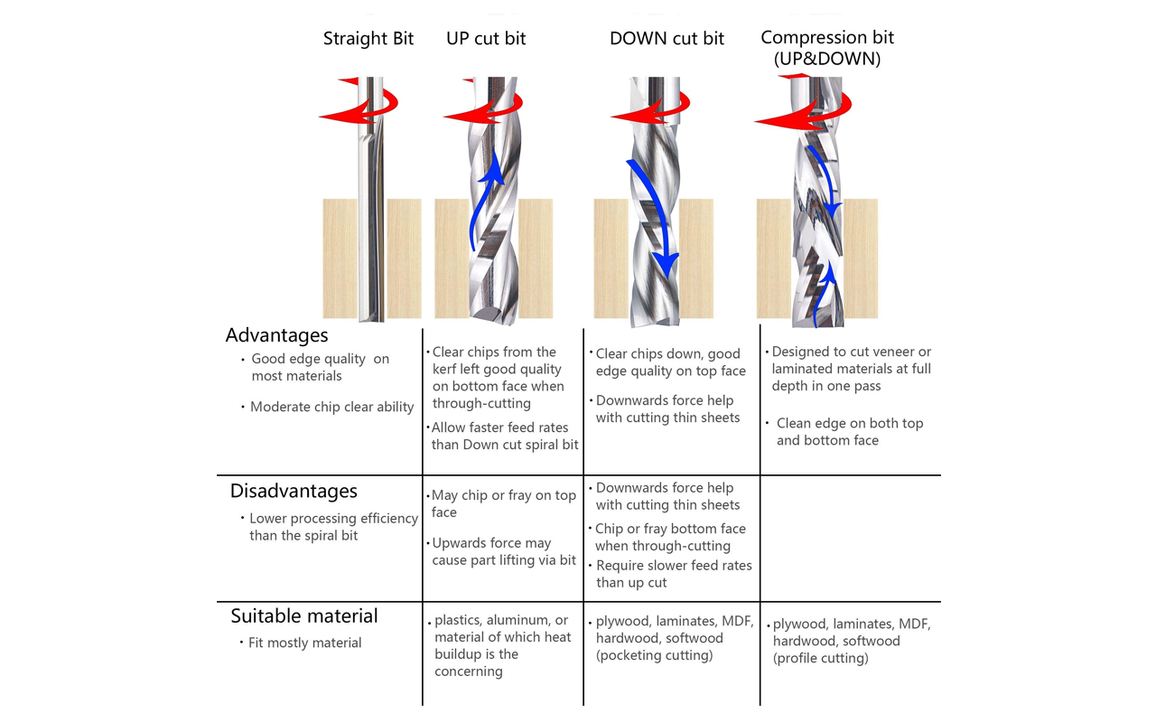
And just to explain a little further on milling bits, the main differences of an Up-Cut and Down-Cup milling bit is the way it removes the chips/waste. For Up-Cut bits, logically by its term, the chips/waste will be remove upwards and vice-versa, for Down-Cut bits, the chips/waste will be remove downwards. Up-Cut bits will give you nice cutting edge at the bottom of the surface but a rough and full of burrs edge on the top surface while Down-Cut bits give you the direct opposite.
Hence, it all boils down to the types of material and thicknesses that we are milling. So in my case, I am using a plywood of 25.4mm, it is most ideal to use a Down-Cut bit since it is only 25.4mm in thickness and it gives us a nice finishing on the top surface without many burrs which will save us time and effort to do post-processing sanding.
But one thing to take note is that for Down-Cut milling, the chips/waste will always be stuck at the bottom since there is not space for the chips/waste to be remove/escape and that is why it is not good for thick material milling as it will create heat and burn within the material especially wood. However, there is a trick to solve this issue which is to ensure that your Cutting-Depth goes beyond the milling thickness of the material i.e for 25.4mm plywood, we should mill it at a Cutting-Depth of at least 26mm or 28mm so that a channel will be milled on the stock material below the plywood and this channel will act as a groove space for the collection of chips/waste during the milling process. So by doing this, you will minimize the build-up of chips/waste during milling and no burning and over heat may occur.
Hopes this tip comes in handy for people who wants to try CNC milling.
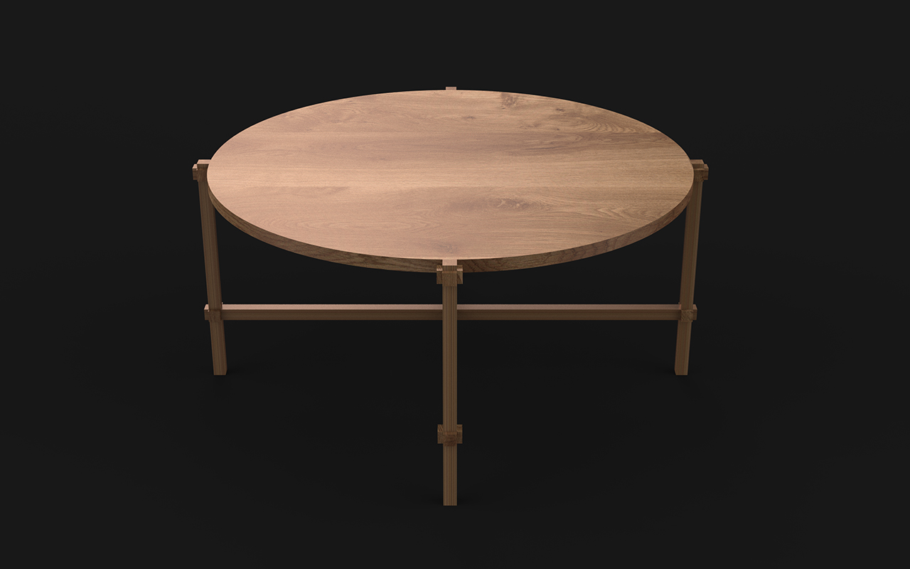
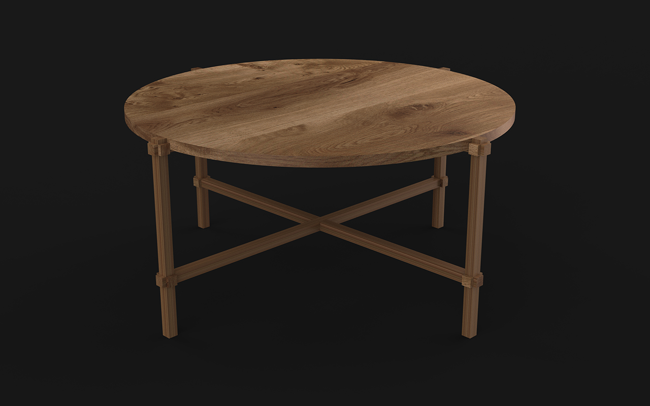
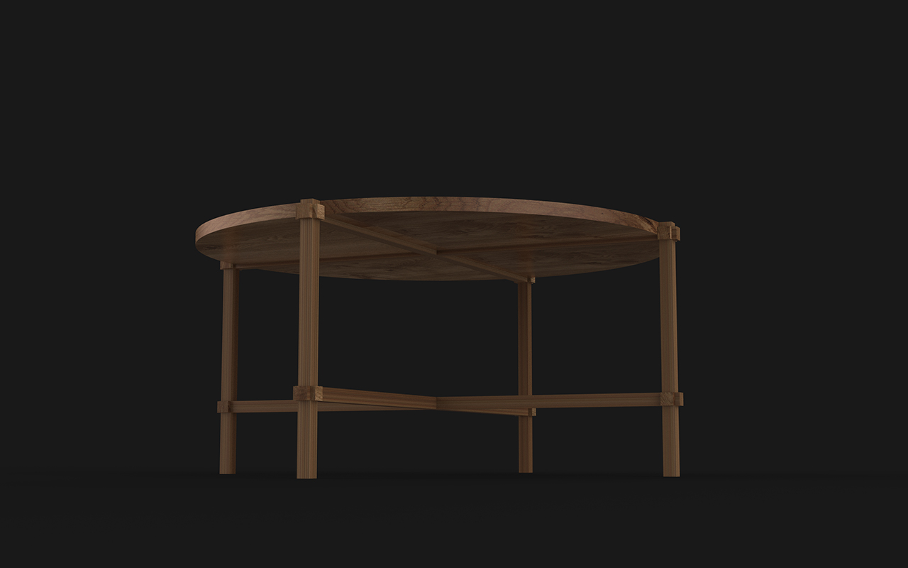
Reflection
It was a fruitful week as I have use the CNC milling machine to fabricate my coffee table. But it is with regret and disappointment that the CNC milling process did not go well due to material issue not once but twice! If I have the time, I will probably get better quality materials such as solid timber like Teak or even Maple wood and I am very sure that it will turn out good. In the meantime, I also did a 3D rendering of my coffee table to see how it will appear in solid wood - Teak. The result of the rendering look amazing and I really hope that I can redo this coffee table again when time allows.