3. Computer Controlled Cutting
This week I started to work on computer controlled cutting that includes using vinyl cutter and laser cutting machine which I am very familiar with. Also starting from this week we will have our group assignment. The group assignement is to characterize the laser cutter's parameters in terms of power, speed, kerf & joint clearance.
Our group members have work together on testing these parameters on an Epilog Fusion Pro laser cutting machine.
You can access the group assignment HERE.
Vinyl Cutting - Silhouette Studio & CAMEO
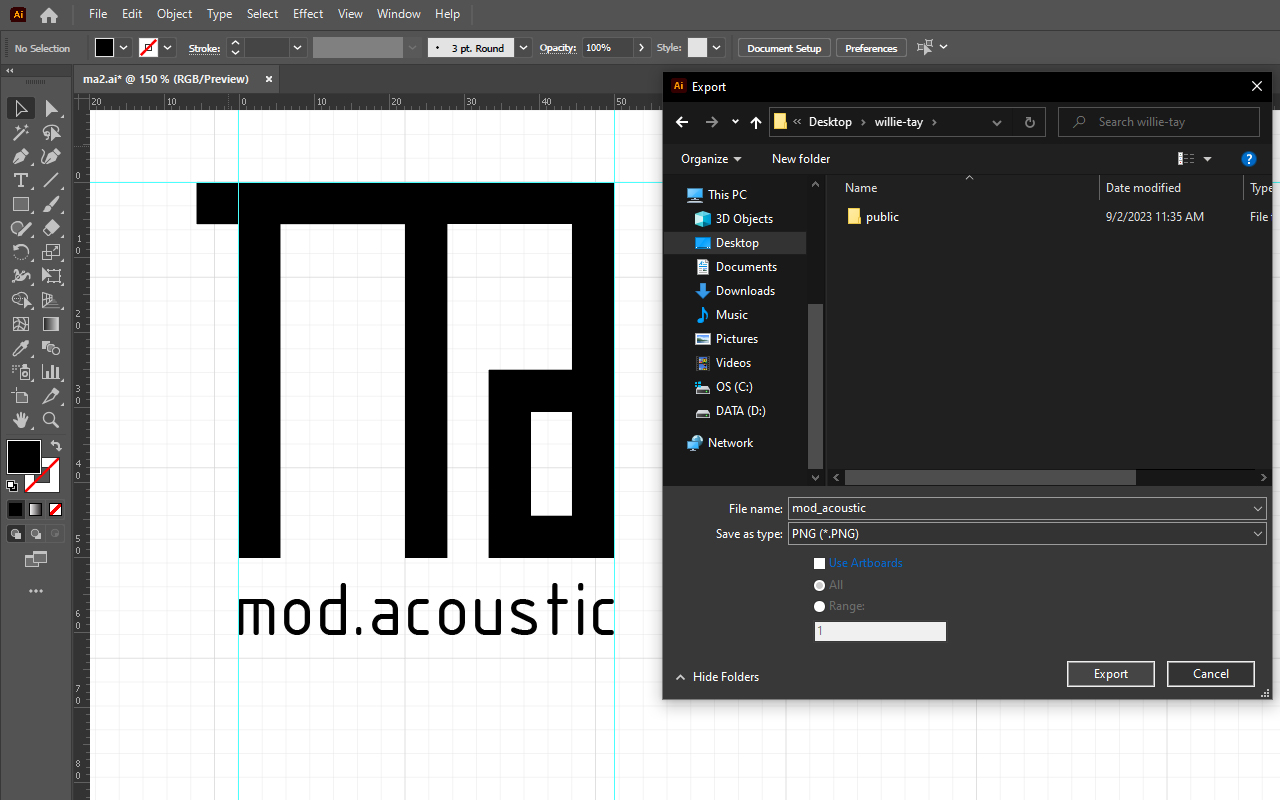
Today I am going to do a test cut of my logo design which was created last week using Adobe Illustrator. Firstly, I need to export my artwork into PNG format as I am using the free version of Silhouette Studio which does not allow me to import SVG (Scalable Vector Graphics).
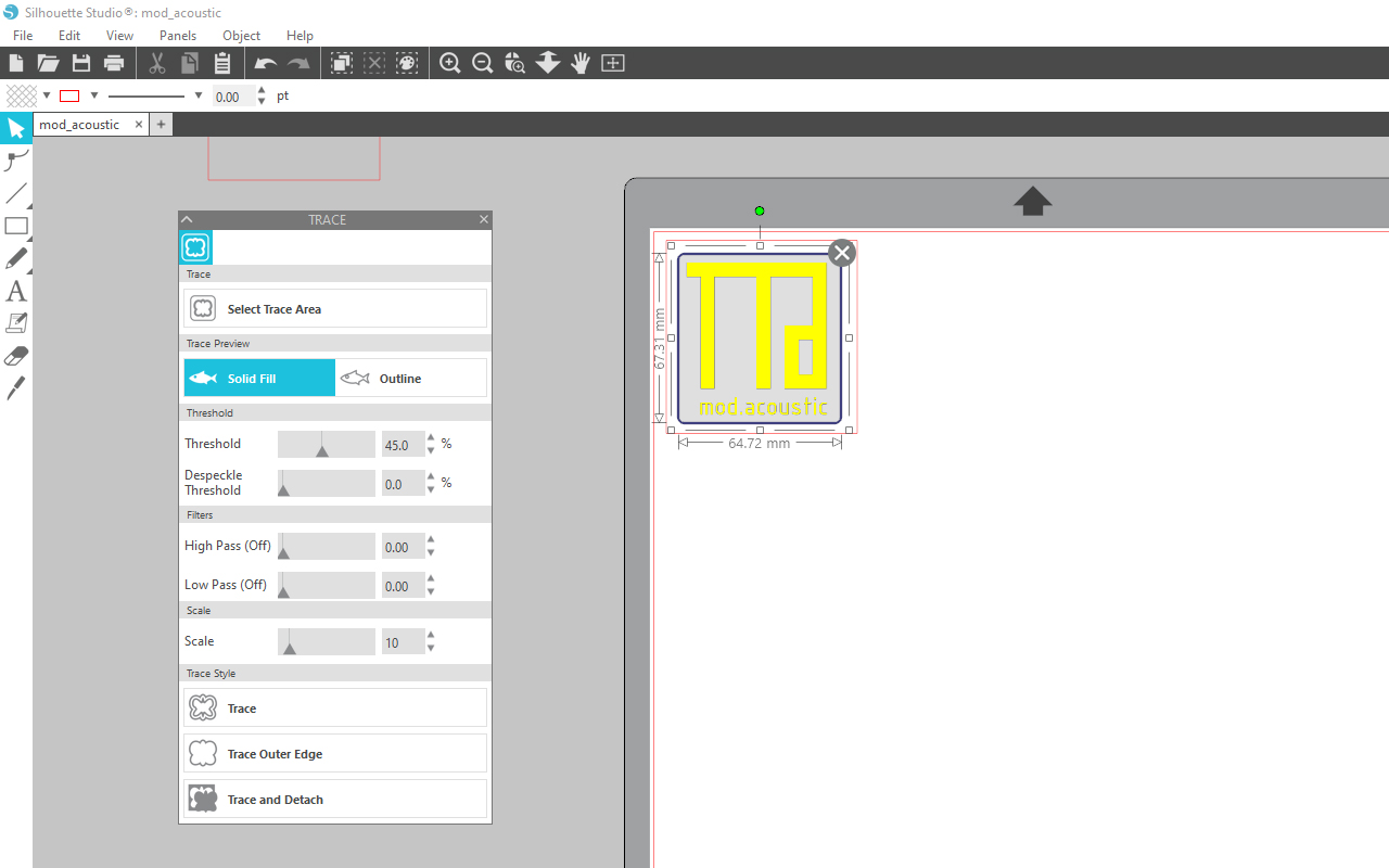
I then need to do a Trace function in Silhouette Studio to create the vector lineworks for cutting.
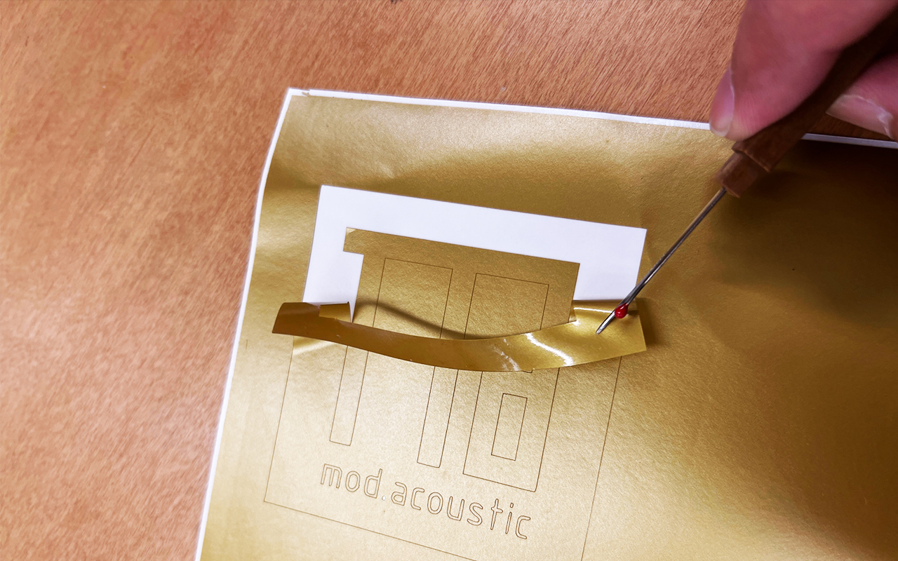
After the linesworks are created, I then link up the CAMEO vinyl cutter to my laptop and proceed to adjust the parameters for cutting. As I have done vinyl cutting before and familiar with the parameter settings therefore, I did not do a test cut which is a recommended step to all who have not done vinyl cutting before.
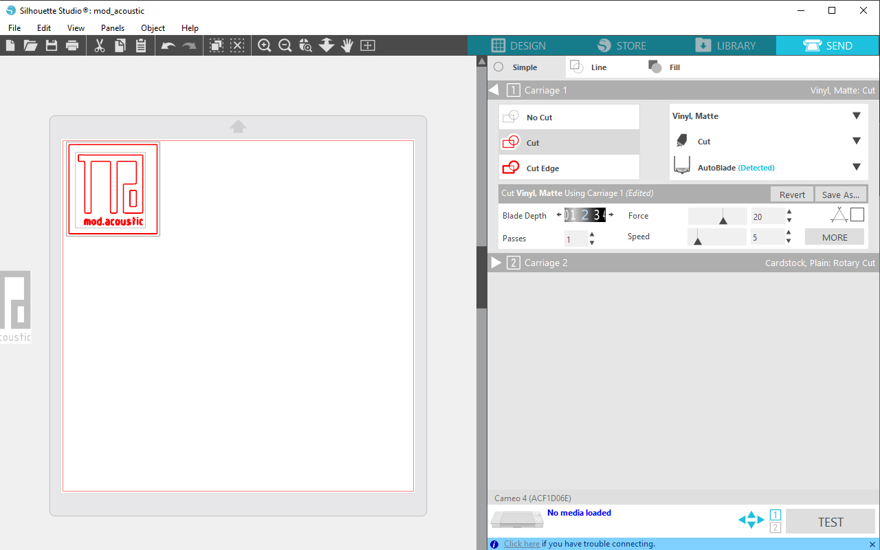
The next step will be pretty straight forward which is to send it for cutting. But before that, I will need to feed in the vinyl paper by pressing the "V" button on the CAMEO cutter located on the bottom left hand corner.
After the cutting is done, the next step is to remove the unwanted layer of the vinyl using a probe tool so that it is easier to remove the vinyl.
After removing the unwanted vinyl layer, we will need to use the vinyl transfer sticker so that we can transfer and stick the vinyl to whichever place we want.
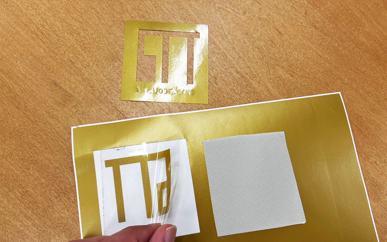
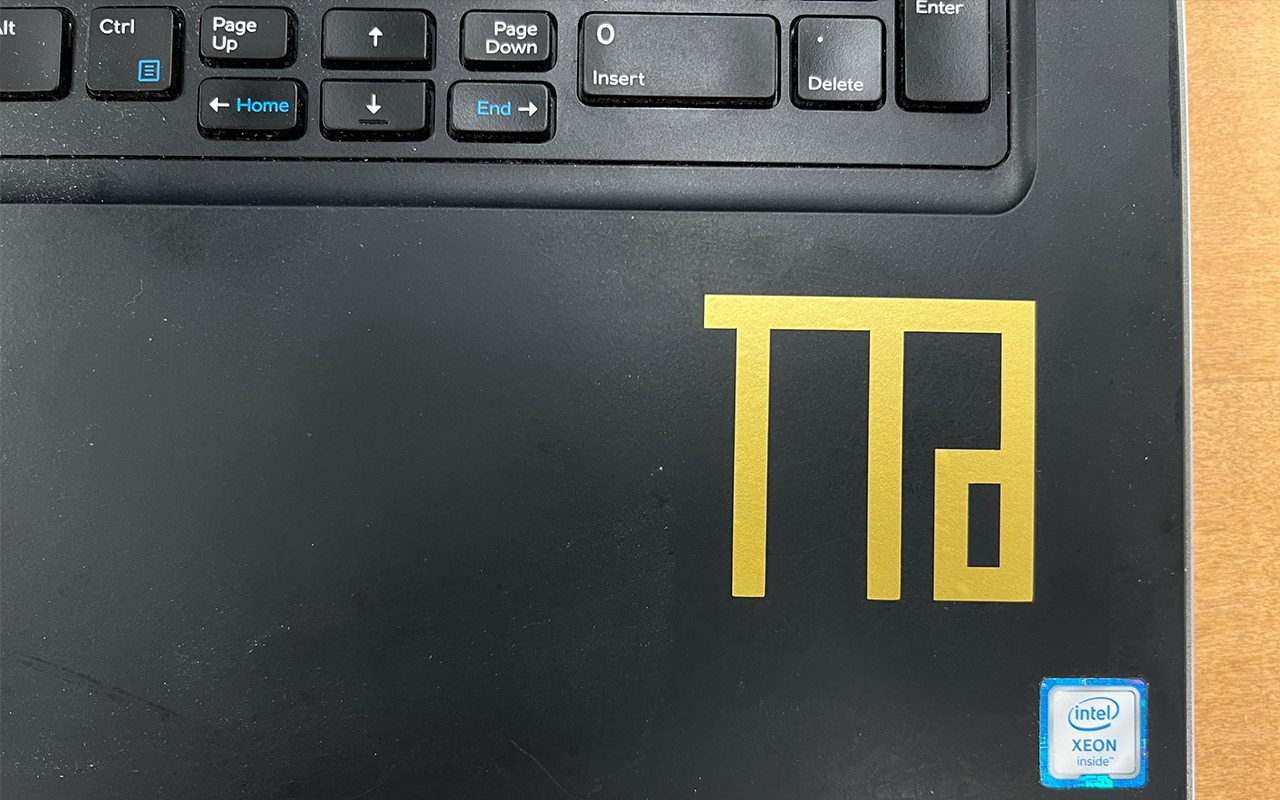
The last step will be to transfer the final vinyl logo to the place I want, in this case, I actually stick the vinyl onto my laptop.
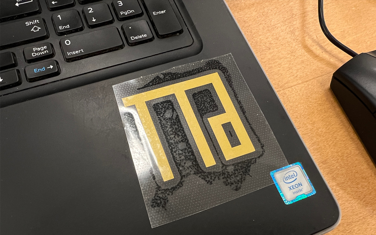
And that is how it goes. So far so good except that during the process I have made a mistake of not accounting the size of my typeface font vinyl cutout as it appears to be too small and it is difficult to be transfer over. Even in the process of cutting, the dot character in the logo was lost even before I actually tried to remove the unwanted vinyl layer. So end of the day, it is still a good practice to always start with a test cut irregardless whether you have experience or not.
You may download the silhouette studio file HERE.
2D Laser Cutting
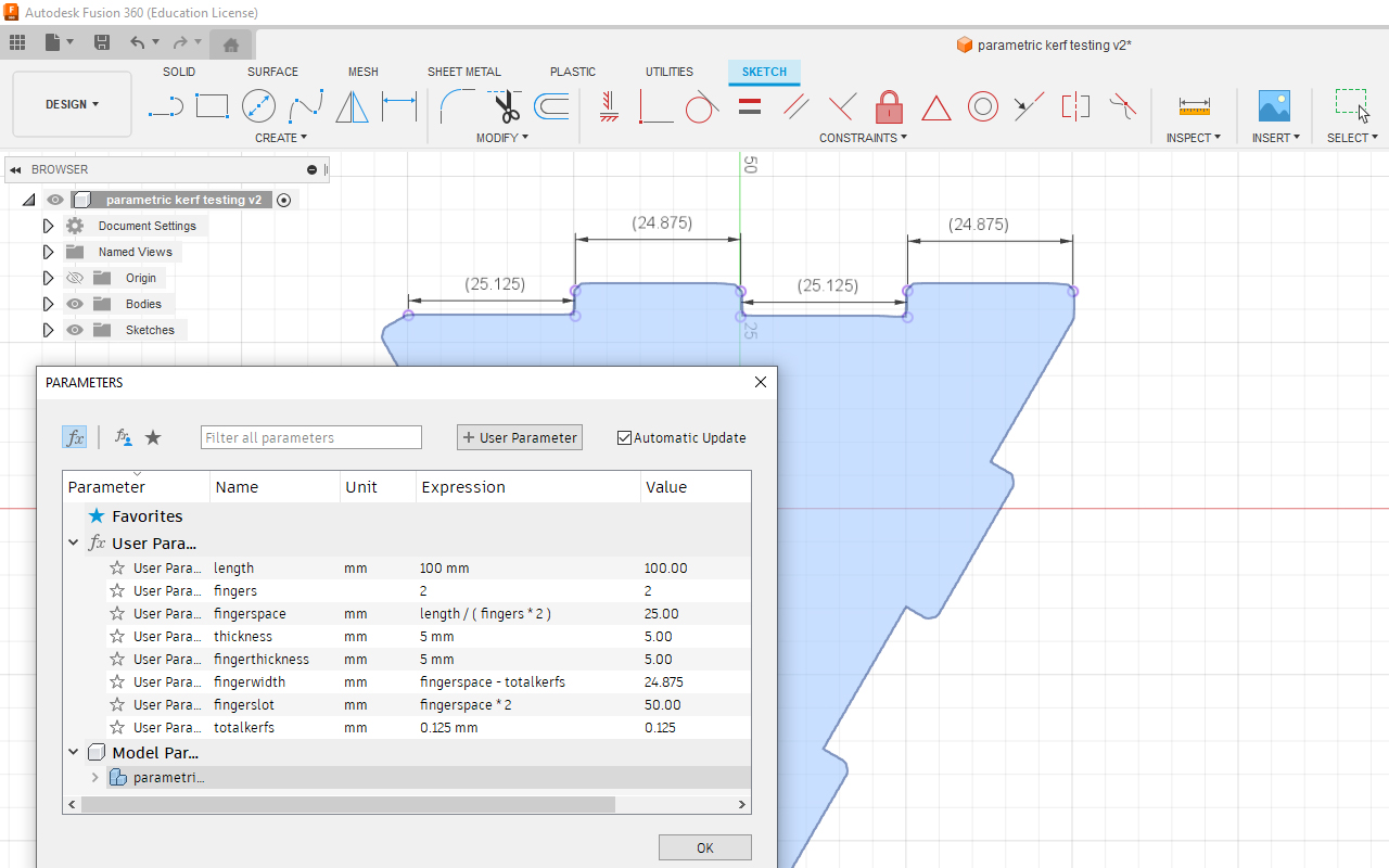
The next exercise is to understand the cutting kerfs of using a laser cutting machine. Laser cutting machine is one of the most versatile and userful fabrication tool for 2D works however it does have its limitation especially when your work requires some sort of assembling and fixing processes. So as a start, I uses Autodesk Fusion 360 to create a parametric model design (taking reference from Platonic Solid Structure Design) that can be assemble to become a pyramid-like structure - Tetrahedron. The reason for using Fusion 360 is because it is easier for me to do dimension changes without the need to redo everything all over again should the kerf allowanace is too small or too big.
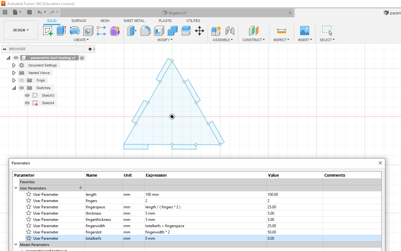
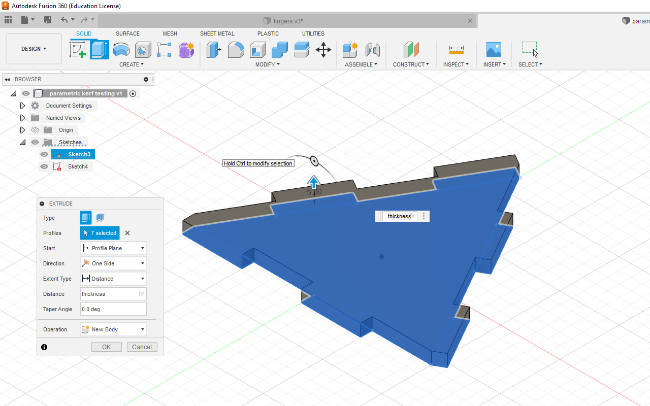
After setting all the parameters using the Parameter Function tool and created the Tetrahedron sketch with finger joints, I then used the Extrude function in Fusion 360 to create the model.
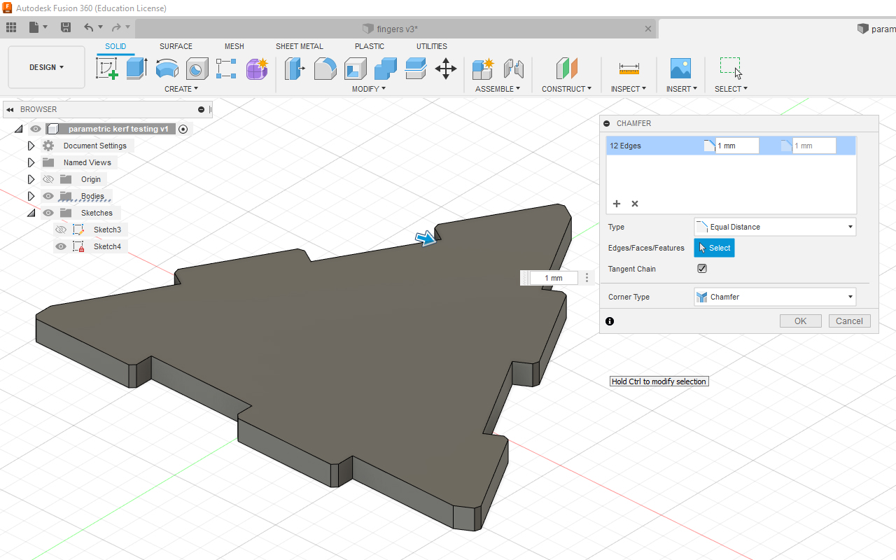
After extruding, I use the Chamfer function in Fusion 360 to create chamfers on all the finger joint edges so that it allows for better slotting.
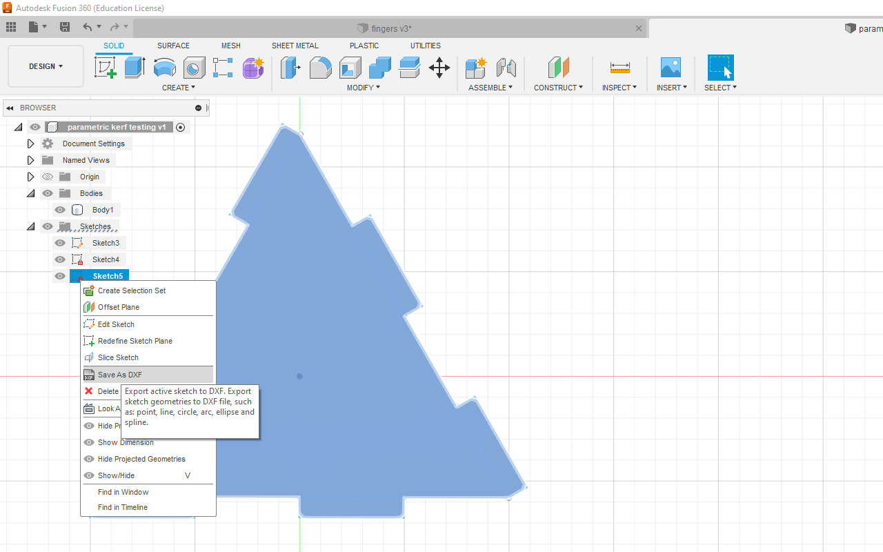
After extruding and chamfering the model, I create another Sketch so that I can export the vector linework in DXF format which then allows me to import the vector linework into CorelDraw for placement and then eventually send for laser cutting.
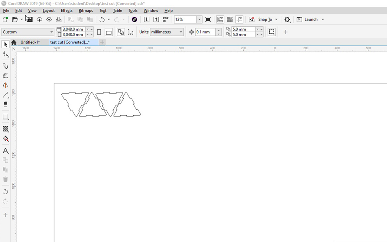
Next, I import the vector linework into CorelDraw and duplicate 3 more copies of the design using the Duplicate fuction and then send it for cutting. In my case, I am using a Universal Laser Cutting System that comes with its dedicated software for laser cutting.
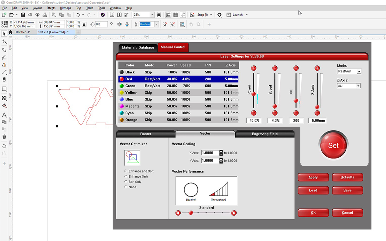
Through the Universal Laser Cutting software, I will need to adjust and select the correct parameters so that I will not burn my work during laser cutting and to create unnecessary fire hazard as the tendency of burning is very high due to incorrect settings. In the software, there is an in-build library of different materials vector cutting and engraving parameter settings which make it easy for anyone to use the laser cutting machine. In this instance, I am choosing the 5mm plywood setting since my model is base on 5mm thickness as shown in the red color vector setting.
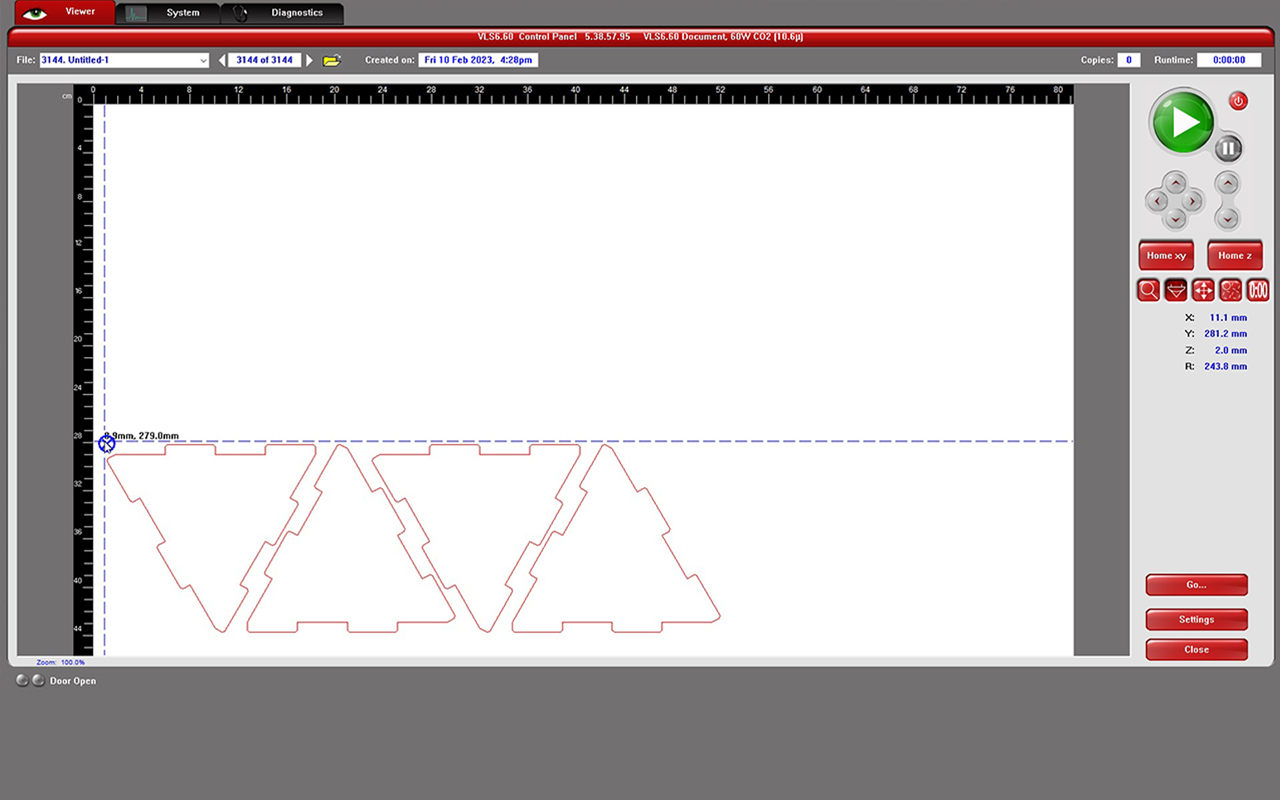
After the settings are done, the last step before cutting is to ensure the placement of your design. Once I have adjust the placement to where I want, I then press the play button located on the top right hand corner of the software UI to start the laser cutting process.
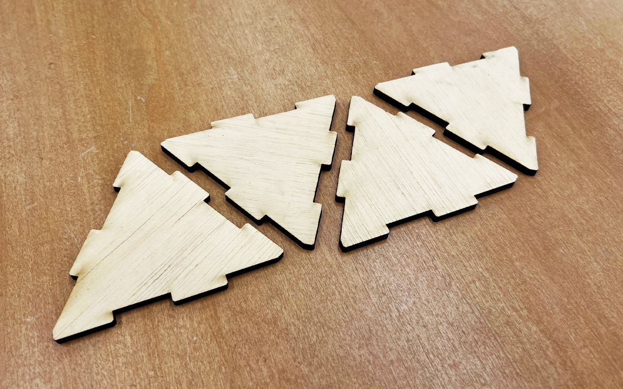
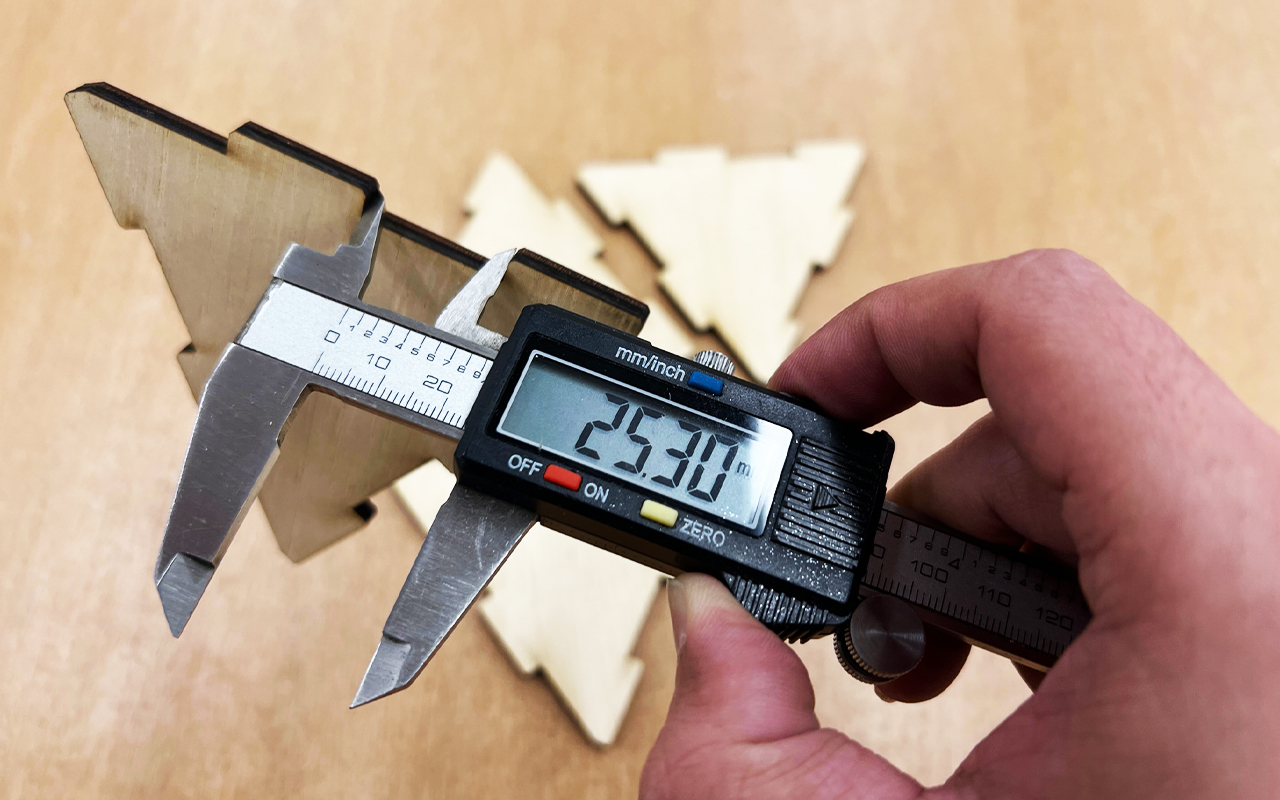
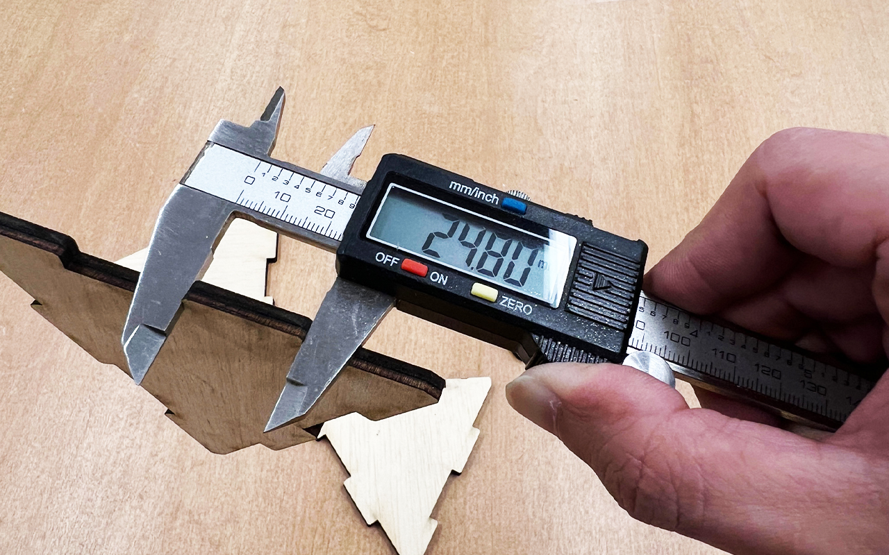
However, due to the kerf effect during the laser cutting process, the finger joints are not fitting together nicely and they are quite loose which make it difficult to be assemble together. The image below shows the Tetrahedron design parts that was being laser cut but because of the kerfs, the joinery are loose and the parts will topple when you tried to move them.
I then need to go back and do some measurement to see how much are the kerfs. I found out that there is a difference of around 500 microns between the finger joint. I then use 500 microns to divide equally to all the edges of the finger joint which is about 125 microns, changed the dimension in Fusion 360 and send it for laser cutting again to test if the allowance is fine.
After changing the dimension, I then proceed with the same steps to laser cut the amended vector linework.
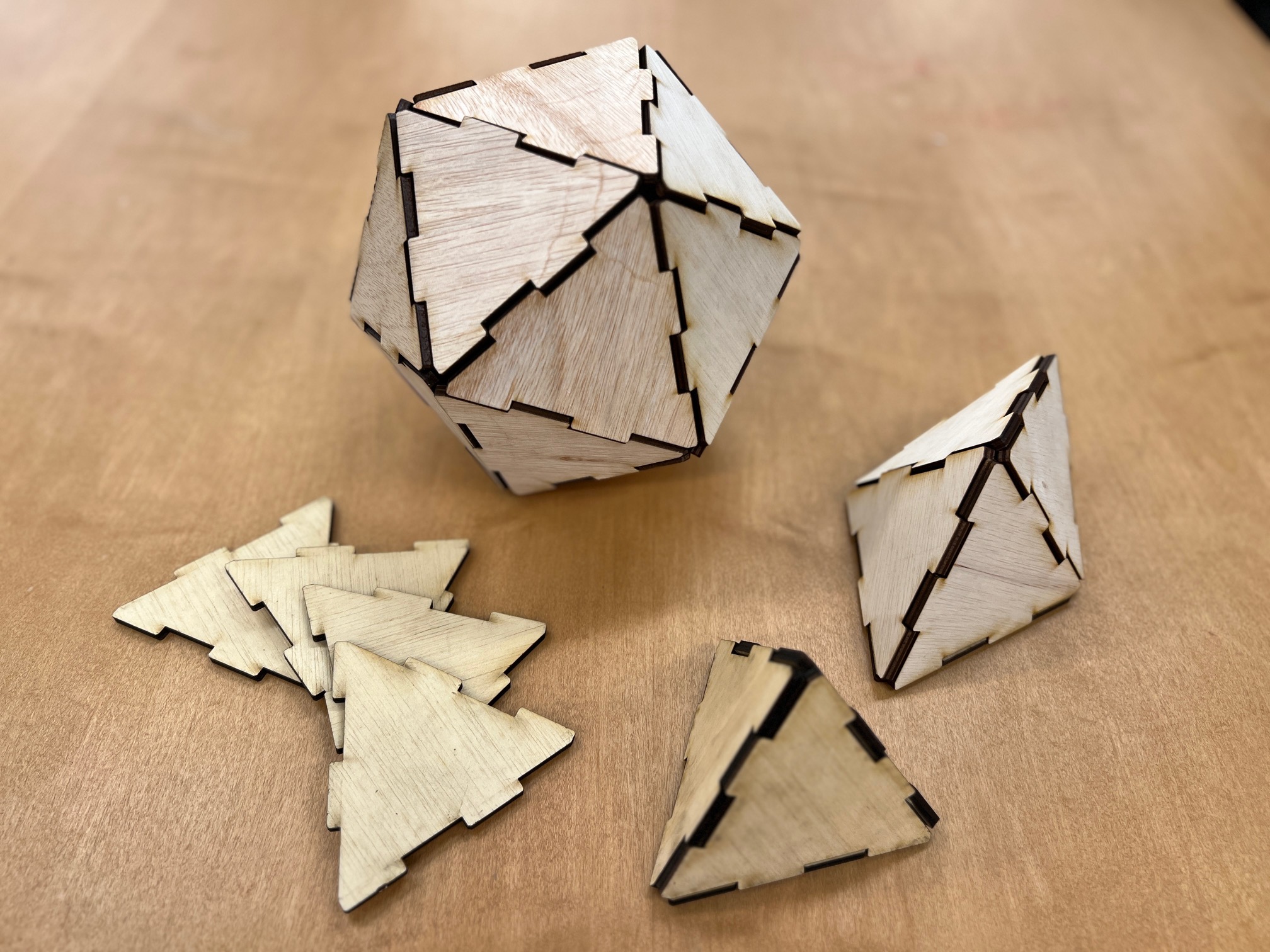
Once the laser cutting is done, I try to assemble the parts again to see if I can acheive a good fit to make the Tetrahedron structure and fortunately, the new dimension with the kerfs measurement works! It is stable and not falling apart even when I try to toss it around.
And with the dimension fixed, the parametric platonic solid structure design can be scaled to different sizes and assemble to different platonic solid structure such as Octahedron and Icosahedron. It can even be assemble to become an even larger modular structure.
You may download the platonic illustrator file HERE.
Reflection
This week is pretty straight forward and I did not experience any difficulties while working on the assignment. However, I did took some time to think about the formula in making the parametric setting in Fusion 360 for making the platonic structure design and maybe I can do a few more test on the kerfs so as to get the perfect measurement.