My Final Project
This is where I will start defining my final project idea!
Design Brief
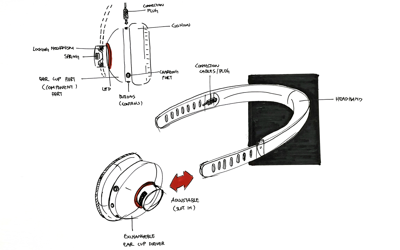
As mention earlier in my assignment 1 documentation, my final project is to design and create a modular headphone that has interchangeable parts and it comes in different materials and design aesthethic styling to accomodate the user's daily style and preferences. Below is a rough sketch concept of what I have in mind for the headphone design:
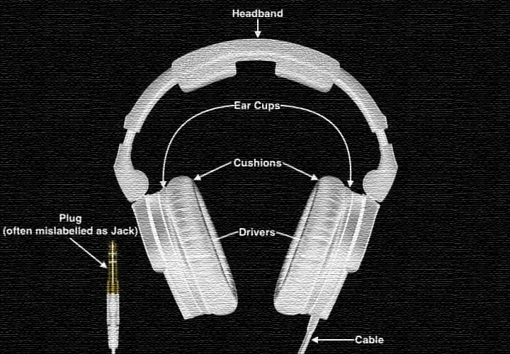
However, for this headphone project to work, I will need to understand what are the main components of a headphone as shown in the headphone anatomy so that I can plan accordingly to get the components and also come up with the schematic of how to link and piece them together. Below is an image of a standard headphone anatomy:
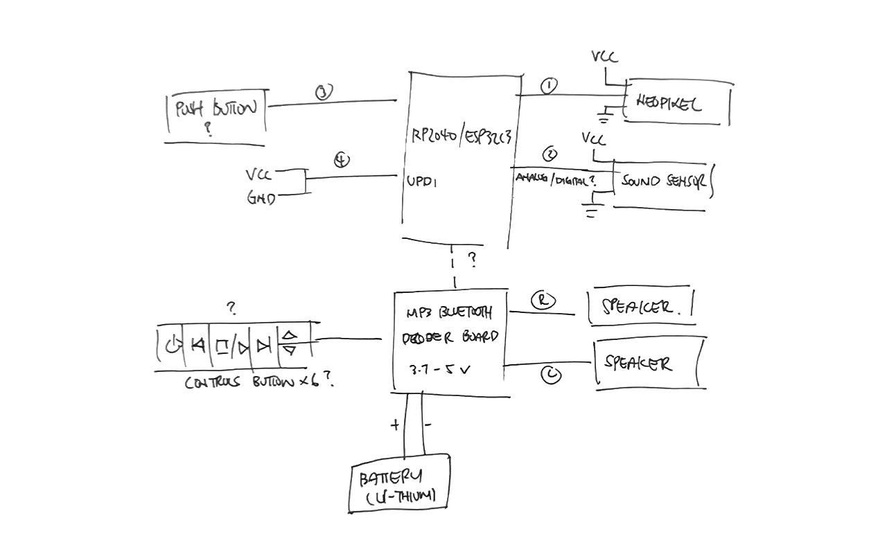
Some of the components are actually quite straightforward such as the speakers, the sound drivers, battery etc. I will need to get these components online as it is kind of difficult to get them locally. The good news is that some of the items are available in our lab so that save me the trouble to source for them. The below image show a draft schematic drawing of the components i need for my headphone design. I was not exactly sure if these are all the components and details I need but it is good start somewhere and seek help later:
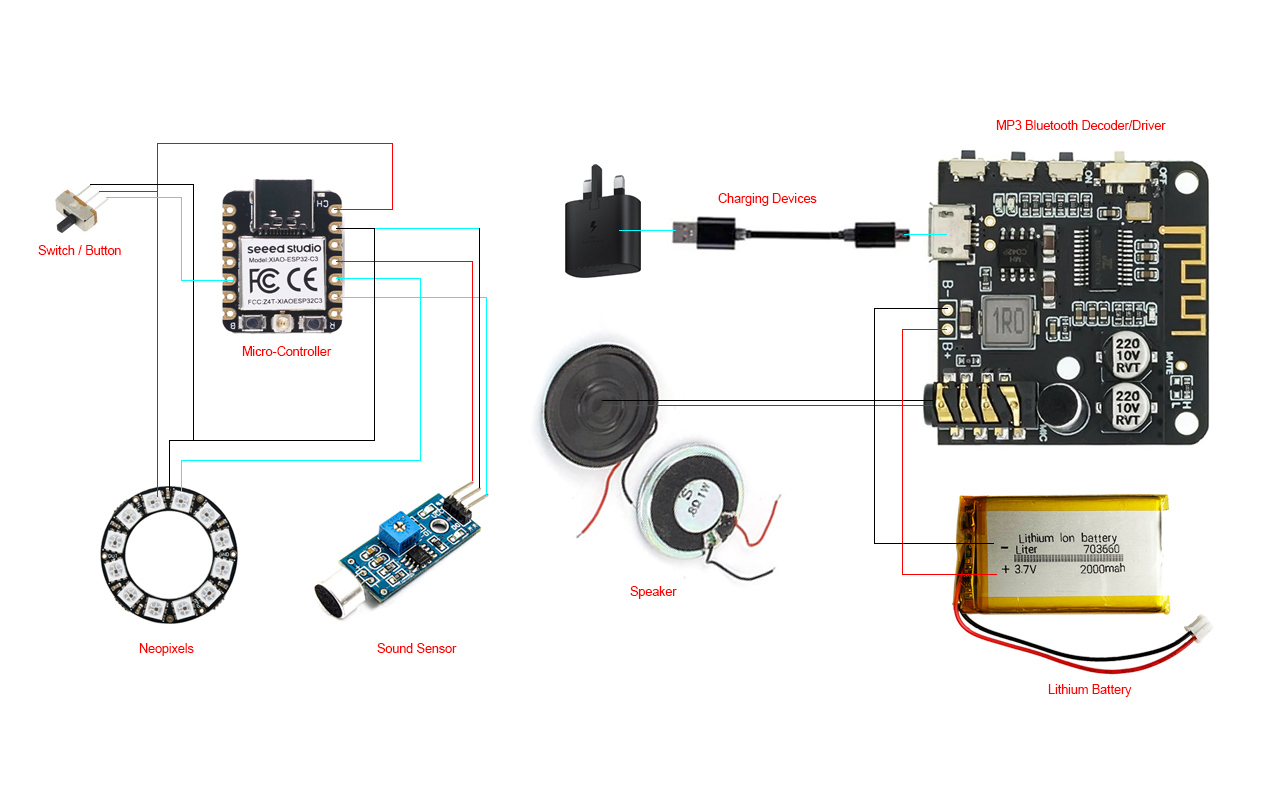
I was then advise by my local Fab Academy Instructor that I may use a MP3 Bluetooth Decorder/Driver Board for the sound system part as it will simplifies my electronic design. Then what I need to do is to create another PCB for my Neopixel and Sound Sensor as one of the main design feature of the headphone design is to create some lighting effects that rhythms according to the music. Below is an image with a clearer picture of what I am going to do in terms of the electronical components and hardware:
3D Modeling & Rendering of Headphone Design
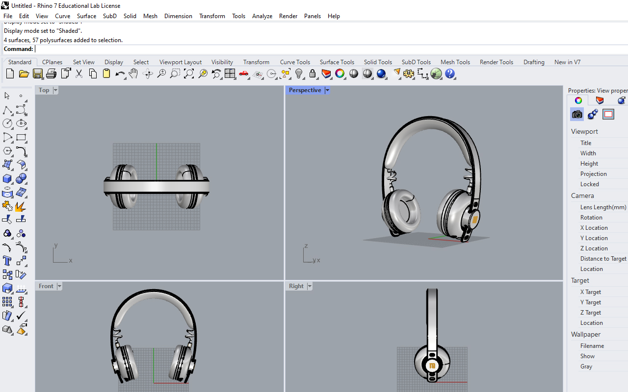
I then created the design in 3 CAD to have a better visualization of my headphone design so that I will know the proportion and dimension that I may need to adjust so as to accomodate all the electronical components within it. Below are some renderings that I have create as part of the CAD assignment:
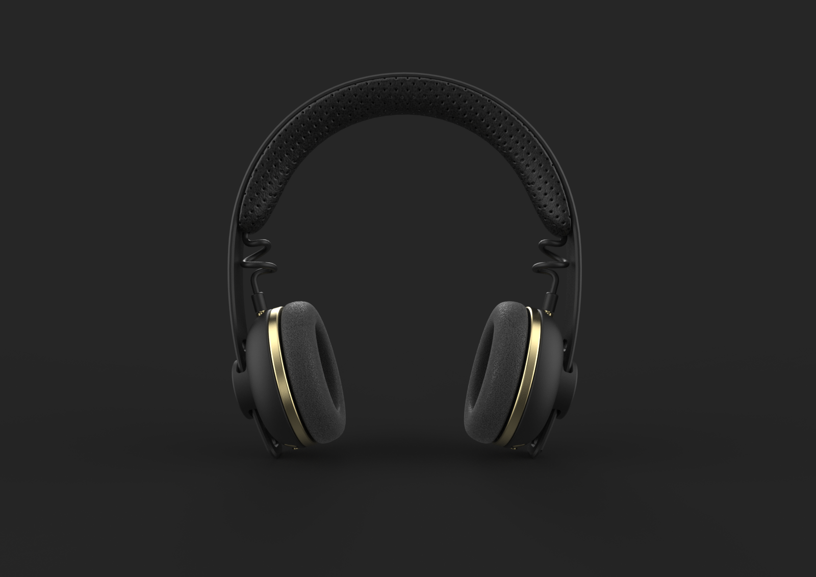
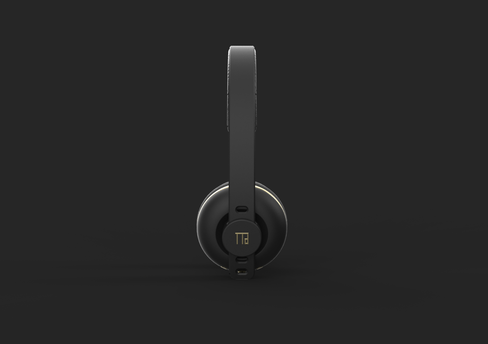
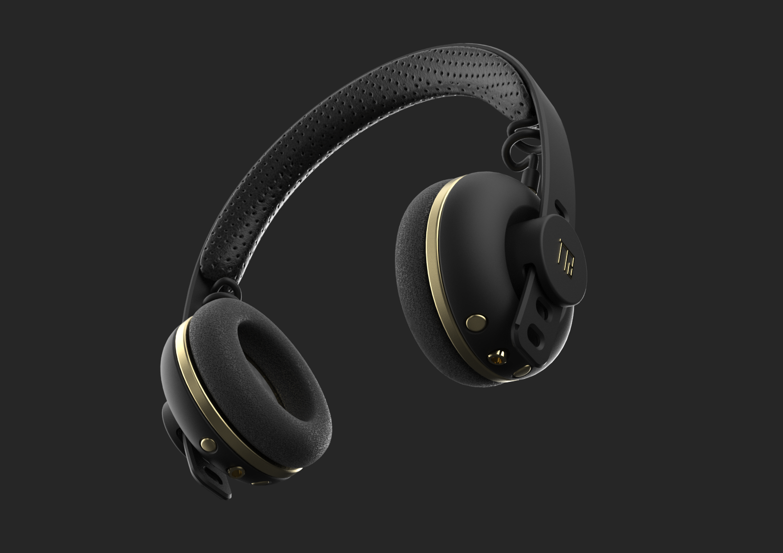
I have also generated a short animation on how the modularity of the headphone design works such that the parts are interchangeble. Just a note that this is just a concept and how I perceive my headphone design may look like. End of the day, the design may change according to the internal component and structure of the assemble process.
Bills of Materials
I have also compile a list of materials with its cost in relation to the headphone project so as to have an idea of how much would the production cost be:
| S/N | Description | Price ($) |
|---|---|---|
| 1 | Xiao ESP32C3 | $7.40 |
| 2 | Speaker (1 W) x 2 | $1.80 |
| 3 | NeoPixels (Ring - 8) x 2 | $4.00 |
| 4 | Lithium Battery (3.7V) | $12.00 |
| 5 | MP3 Bluetooth Decoder/Driver | $2.10 |
| 6 | Sound Sensor (LM393) | $1.80 |
| 7 | Mini Slide Switch | $0.20 |
| 8 | Audio Jack (3.5mm) x 2 | $3.20 |
| 9 | Audio Jack Socket (3.5mm) x 2 | $3.85 |
| 10 | Buttons (6mm) x 3 | $1.65 |
| 11 | Voltage Regulator (AZ1117CH) | $0.60 |
| 12 | Pin Head | $2.00 |
| 13 | Capacitors (1μF and 0.1μF) x 2 | $0.40 |
| 14 | Ear Pad Cushion | $19.00 |
| 15 | Headband Cushion | $13.00 |
| - | Total | $73.00 |
The total component cost of my headphone design is about SGD$73, which is kind of affordable if you were to compare them to other headphone brands that will easily cost you more than SGD$150. The next step for me to do is to wait for all my components to arrive as most of the components are coming from oversea and that takes a little bit of time.
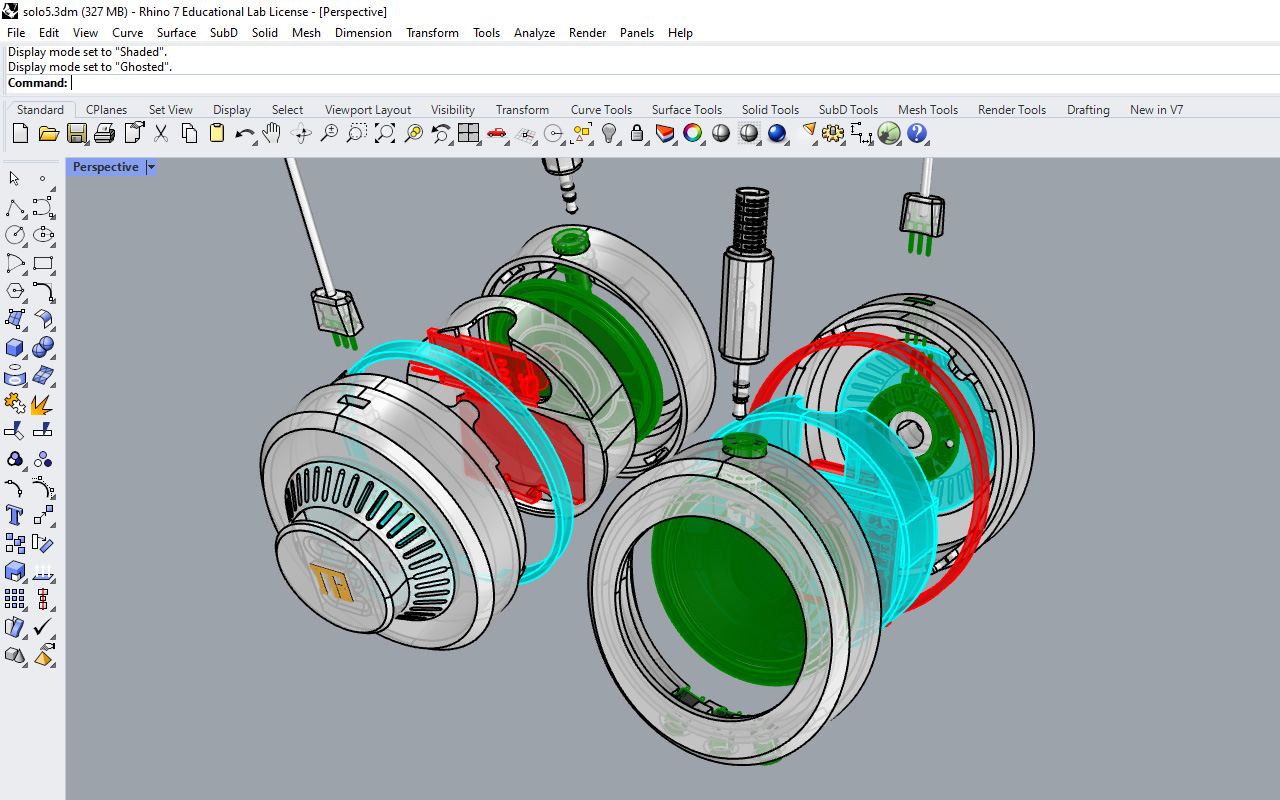
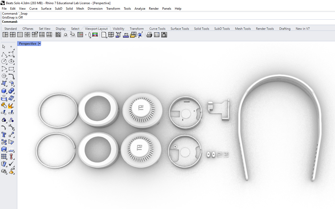
3D CAD
While waiting for the components to arrive, I began to start my 3D CAD of the headphone design. I have tried to modelled out every single components that I am using so as to get the exact dimension of my parts and to ensure that everythings will fit at the assembly stage.
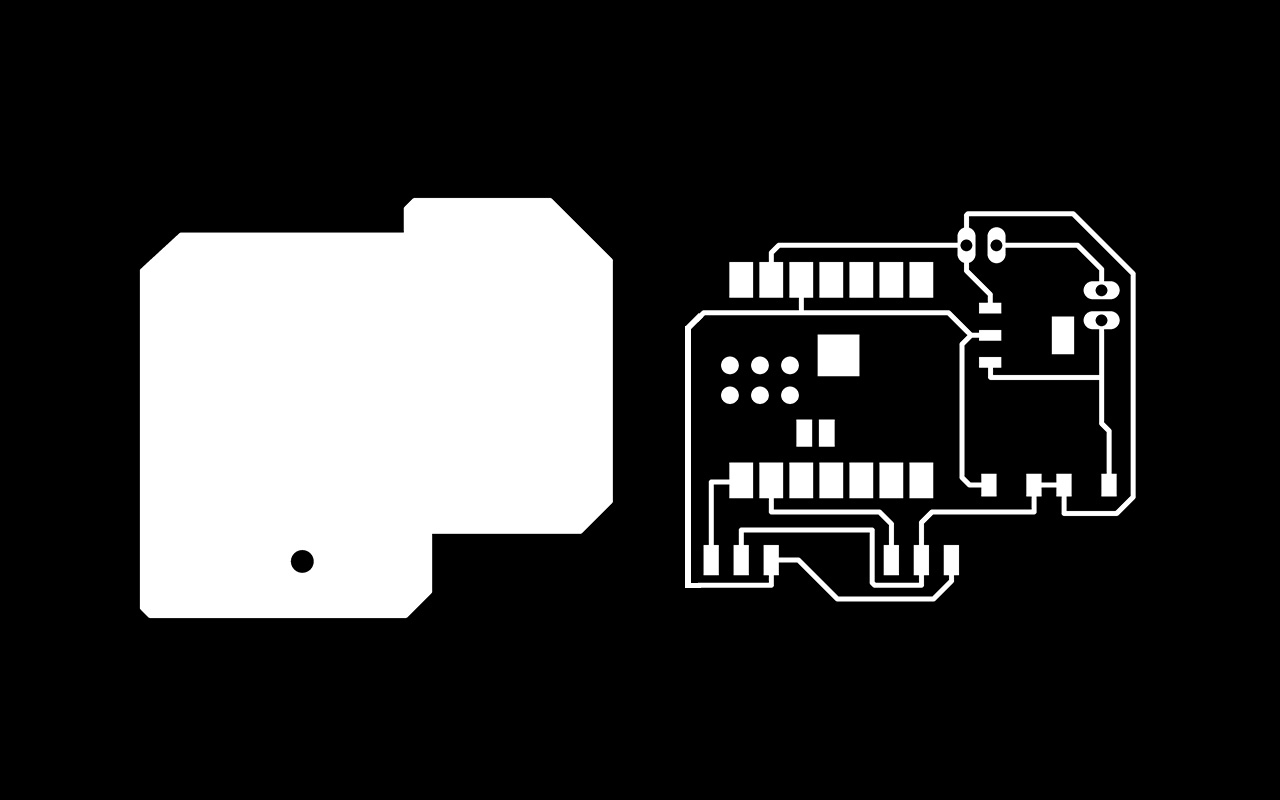
PCB Design
After creating the CAD, I went to create my PCB design using Autodesk Fusion 360/Eagle. As I am going to create a board that communicates with a Sound Sensor LM393 and 2 pcs of Ring-8 NeoPixels, I need to have the following component in place as shown in the schematic drawing below:
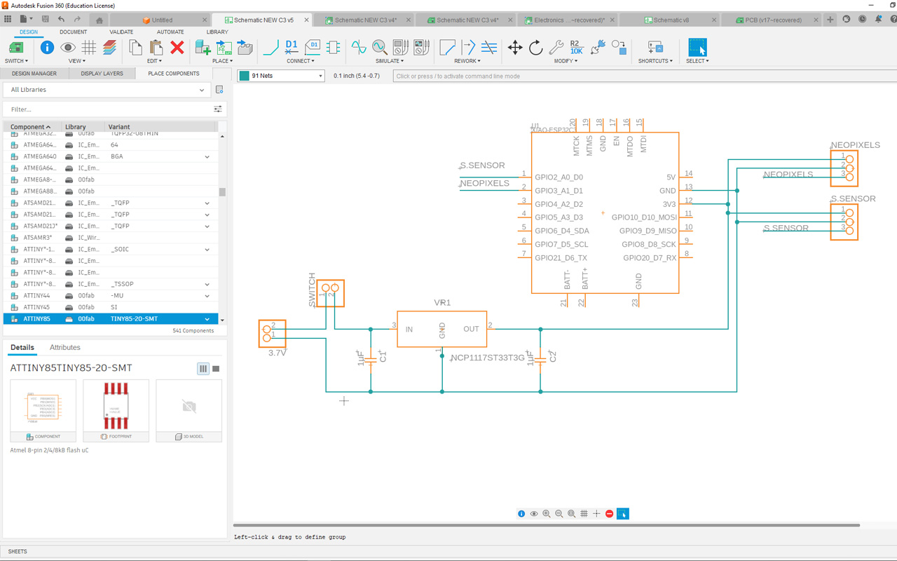
I am using a Xiao ESP32C3 micro-controller and the reason for using it is because initially I was thinking to use the build in bluetooth feature for the communication between the device to headphone. However, it seems that Xiao ESP32C3 micro-controller does not have a audio codex in place at the moment so in other words, I will have to rely on an external Bluetooth MP3 Decoder Board to take care of the MP3 player and connection function. Also, I will need to link all the components to be powered by a 3.7V Lithium Battery and control by a switch slider for the LED pixels. One thing to note is that as I am using a 3.7V lithium battery, I will need to do a voltage regulator so that it will not burn my micro-controller which works on 3.3V. So I will need to use a Voltage Regulator (AZ1117CH) with capacitors (1μF and 0.1μF) to lower the voltage as seen in the image below.
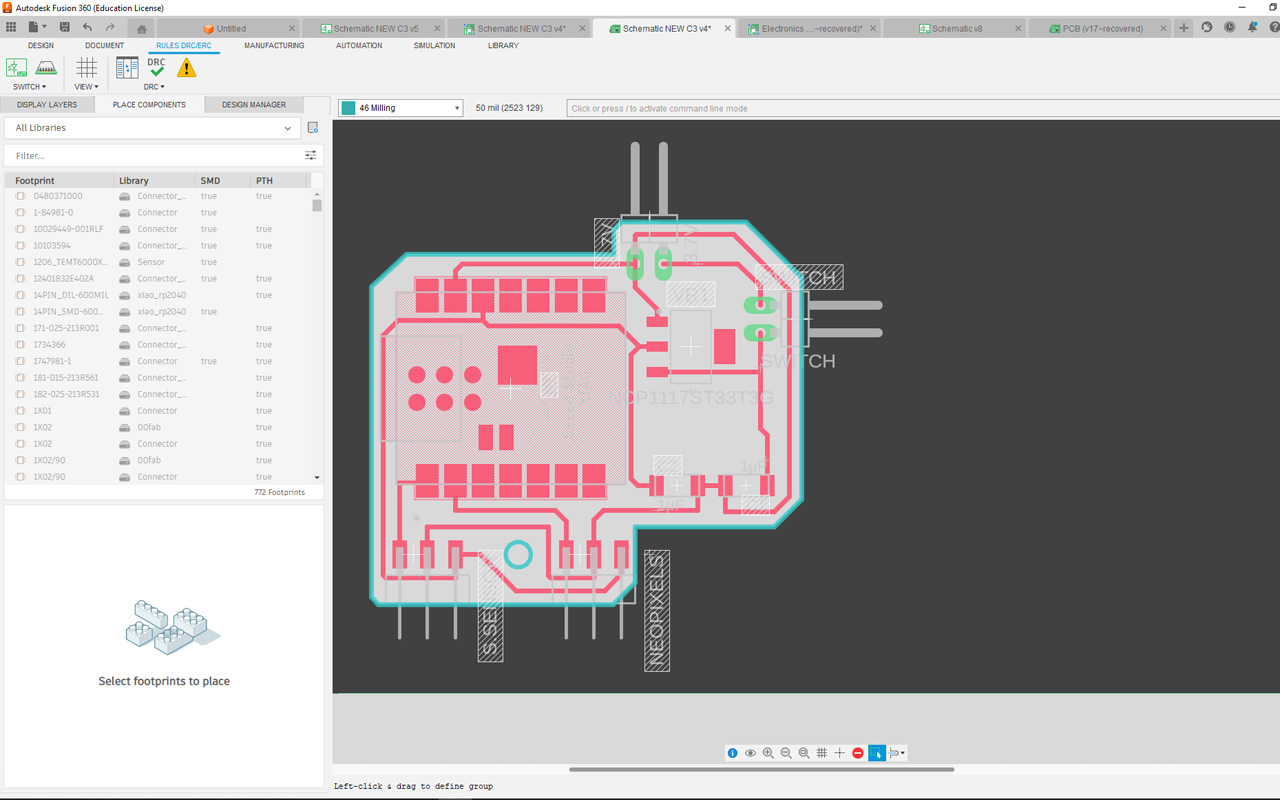
After finishing my PCB Design, I then export the file to the MOD software to generate the G-Code for CNC milling.
Then I proceed to do a 3D print on my 3D CAD parts for test fitting. Below is the video of the 3D printing using a MK3 Prusa FDM Printer:
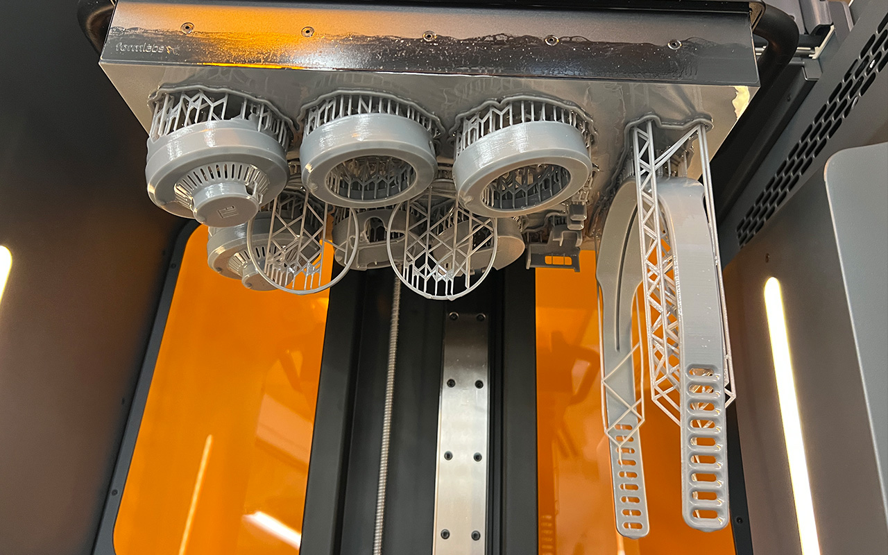
After multiple testing of the fitting doing the relavant changes to the dimensions and allowances for tight fitting, I then use Formlabs 3L to 3D print my final CAD model. The reason for using Formlabs is because it has by far the best finishing of all 3D printing techniques which is crucial for my headphone design. Below is an image of the finished printing process using Formlabs. The total printing time is around 16 hrs which is not very long, consider the amount of parts that it was printing.
After printing, it is again the tedious part of the job, post-process sanding as shown in the image below. The good news is that with Formlabs printing, sanding is very minimal and only on areas where there are supporting structure.
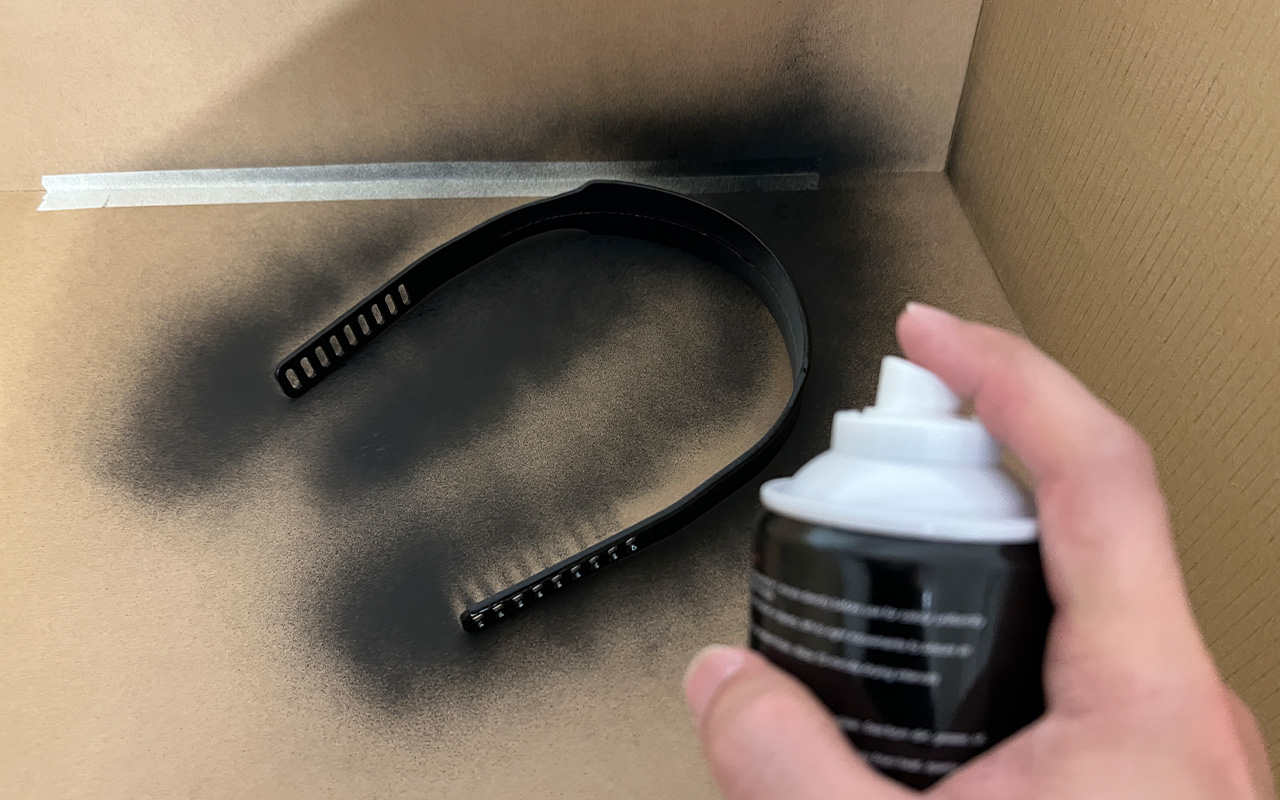
When I am done with the post-processing sanding, I then send all my parts to be spray painted in matte black color so as to acheive a minimalist design outlook.
While waiting for all my parts to dry, I proceed with my PCB fabrication using Stepcraft. Below is a short video clip of the PCB CNC milling process:
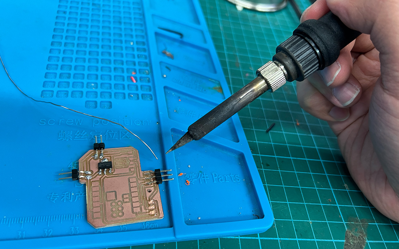
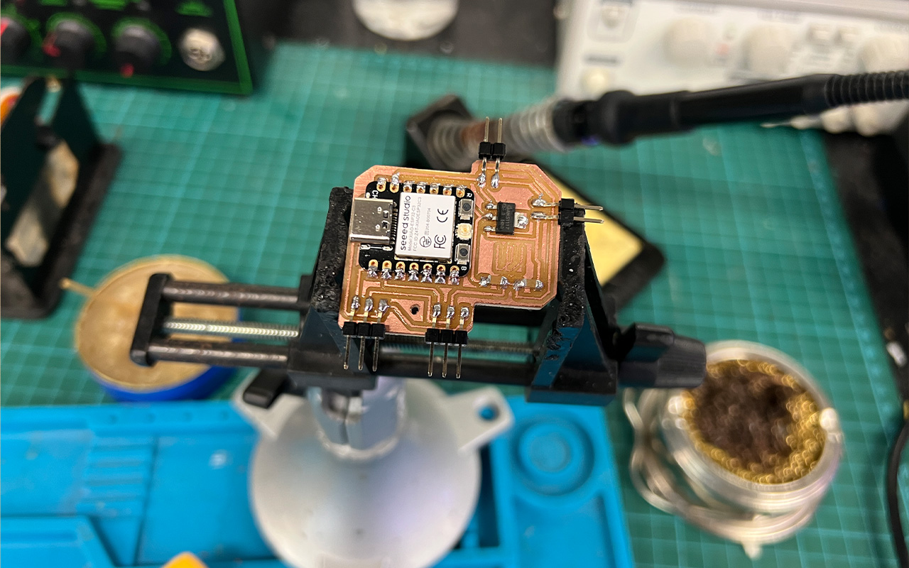
After CNC milling of my PCB, it is time to do the next most tedious work, Soldering. It took me long enough to solder my components together to acheive this:
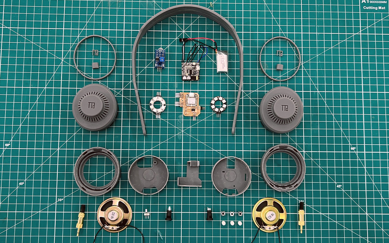
I then decided to layout all my parts (before spray painting) and components and get ready for the final system integration.
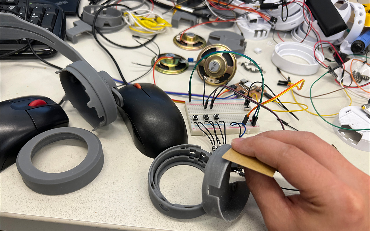
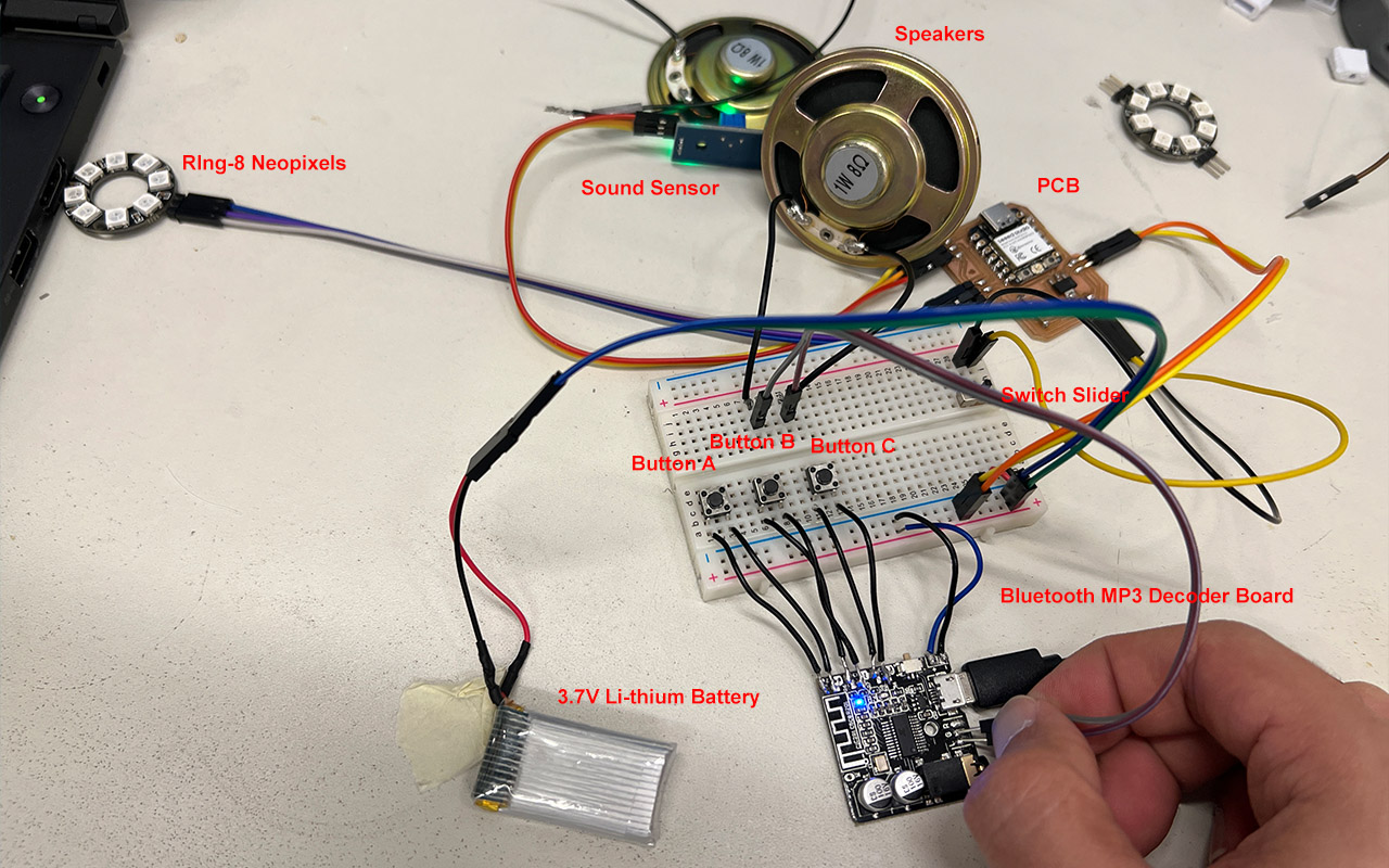
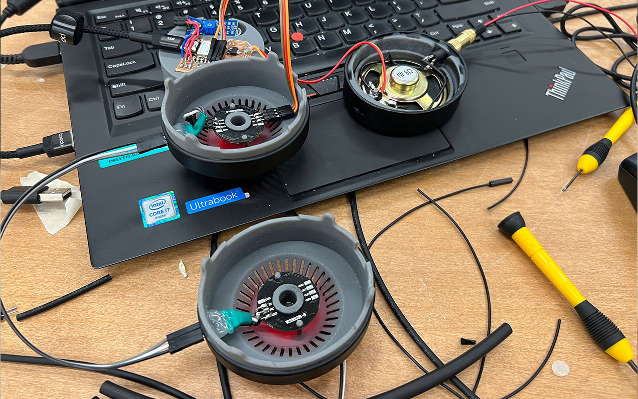
The system integration was quite straight forward as what I need to do is to link them according to the schematic that I have created. But before that, it is neccessary to do a test run on all my components and circuit board as I have no idea if my PCB and components are working well or in good condition. I then link up all my circuit using jumper cables and breadboard for a quick test and below is the video of the outcome:
In this quick bare run test, all components were link up according to the schematic circuit drawings and was powered by just the 3.7V li-thium battery. Basically, there are 2 PCB, one is the external bluetooth MP3 decoder board that communicates with any bluetooth devices and it comes with 3 basic button control of the following:
- Single Press of Button A - Forward Track
- Press and Hold of Button A - Increase Volume
- Single Press of Button B - Play/Pause
- Single Press of Button C - Backward Track
- Press and Hold of Button C - Decrease Volume
The other PCB (fabricated in-house) will be for the Sound Sensor, NeoPixels as well as the connection to the power source which is the 3.7V Li-thium battery. it was tested using 2 bluetooth devices, one using iphone and the other through bluetooth connection to a laptop. Both are working fine. The quick test video shows the music was played from the connected speaker and it can play and pause by pressing button B. As the song was played using youtube, the forward and backward track button does not work in this case however, it does work on Apple music app or Sportify. As I am using my phone to do the recording, I am not able to take the video of how it works in my iphone and showcase it here. This can be done in the future when the project may be further develop as mention in Week 18. Project Development Week.
After testing, I was glad that my project really works! I was actually quite worry that my PCB may not work due to my bad soldering skills and luckily, it was fine this time round. So it was down to the last step which is to do the final system integration with all the parts and components. Below is a video of testing the circuit and components of the Neopixels and Sound Sensor:
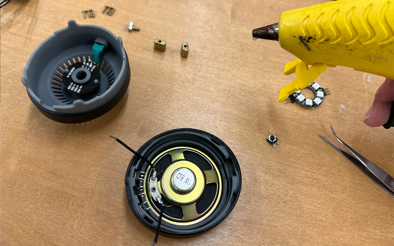
Eventhough I have measure the dimension of every component accurately and I have no problem in installing and fixing the components together, it will be better to enforce the fixture with hotglue so that the connection are stable and will not fall off.
After that I continue my system integration but I had some issue because of the soldering and cables. Eventhough I have delicated enough space for the wiring, it is still a hassle to put them in place. As I am trying to put them in place, the soldering came off! So I have to redo everything again, from removing every components to resoldering of the parts. All these took up an entire day of work as I have lost count on the number of times that I have to resolder the components. Below is an image of the system integration process:
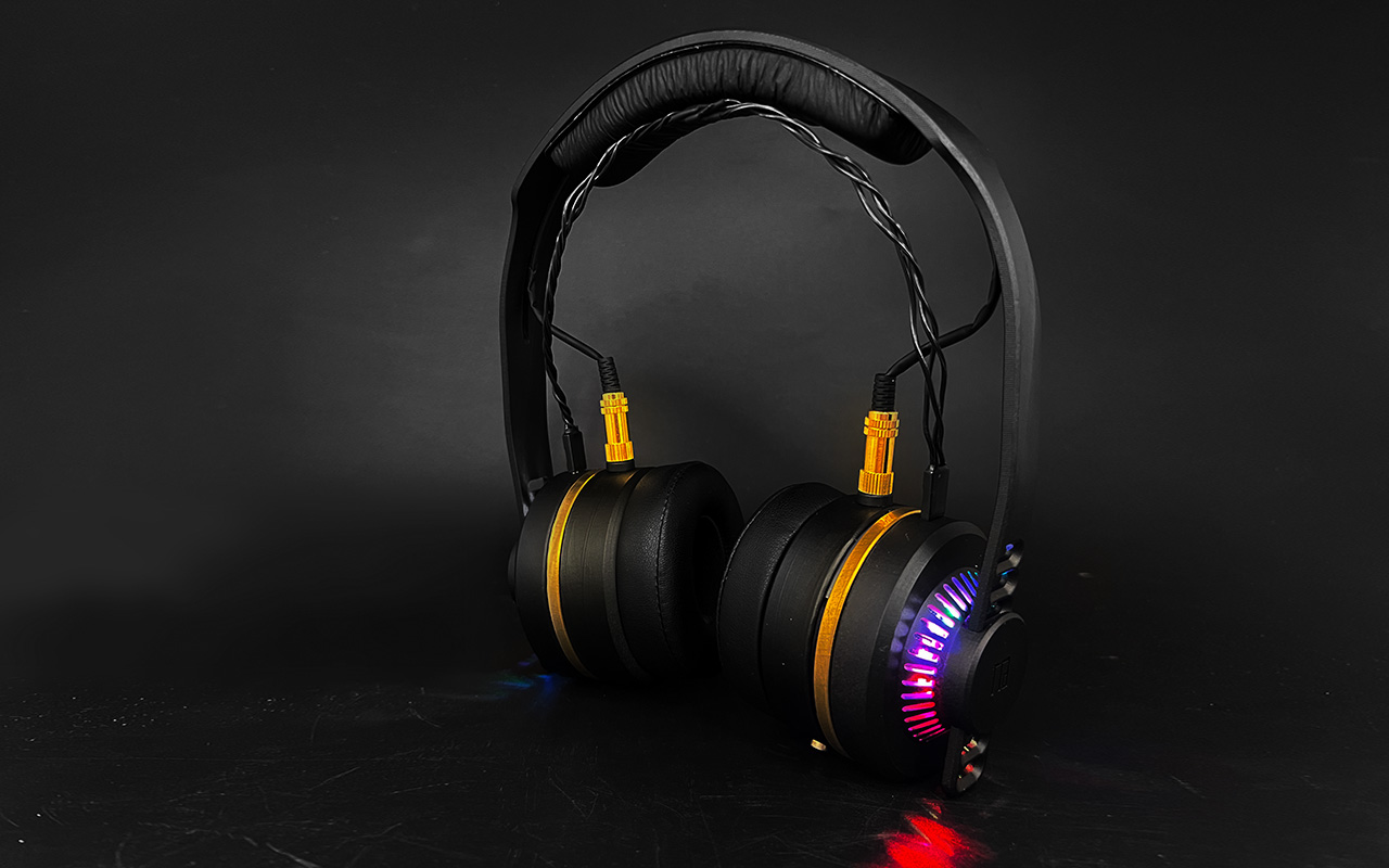
Finally, after a hard day of work, I finally got my headphone fully assembled. But there is a problem as my Li-thium battery runs flat from constant testing and due to a shortage of time to allow it to fully charge, I decided to connect it to an external 5V power supply to do the final run of testing and also for video recording. Below is the hero shot of my final headphone design as well as showcasing its performances!
You may access the Final CAD HERE.
You may also download the Code of the Programming HERE
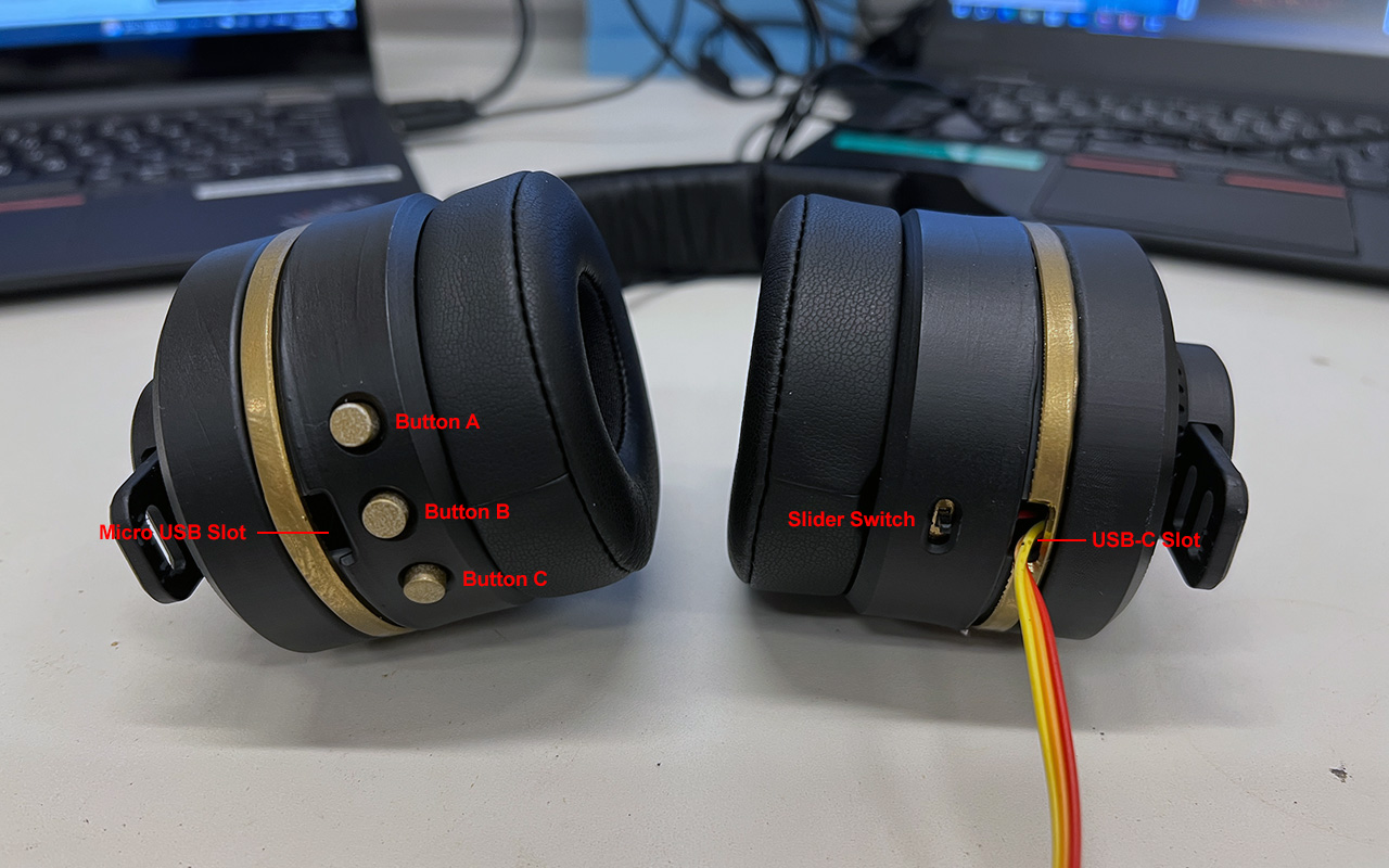
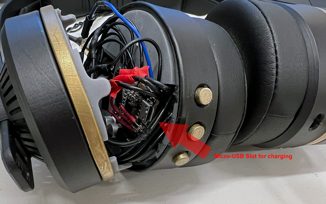
I have also added images to showcase where the buttons are and also the mode of recharging. Basically, at the bottom of the headphone, there is a slot for a Micro-USB cable for recharging of the 3.7V li-thium battery as well as another slot on the other side for PCB board programming using USB-C cable. There is another Slider Switch to On/Off the LED Pixels so that it allows user to choose if they want it to be running all the time or off it to save power.
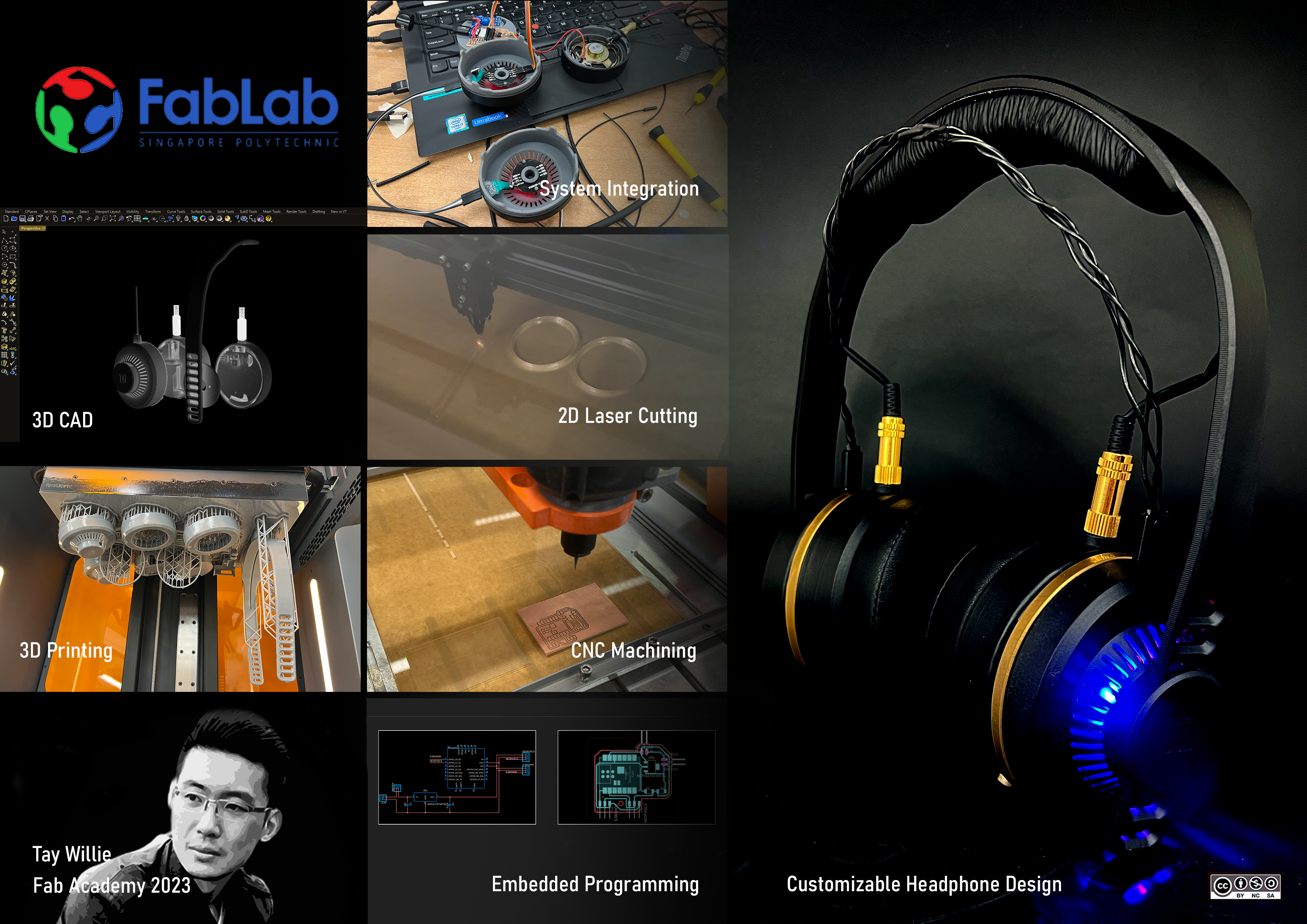
Last but not least, below are the final presentaton board and 1 min video for the final presentation!
Reflection
It was a long and fruitful journey in creating the headphone design. During the process, there were many hiccups and luckily with our local Fab Lab instructors, things eventually got sorted out. I would like to take this opportunity to thank Neil, all Global instructors that gave me inputs and advises and last but not least, our local instructors for meeting us day in day out and supporting us throughout the Fab Academy Journey. It was really a good learning experience and I really have learnt alot from this course. I am very sure that what I have acquired from Fab Academy will be put into good use in the near future.
Last but not least, this project will be license under:
CREATIVE COMMONS ATTRIBUTION-NON COMMERCIAL-SHAREALIKE 4.0 INTERNATIONAL LICENSE
This project is still undergoing refinement at a later stage and is open for collaboration with anyone who may have an interest in it to make it even better.