W12 INPUT DEVICES
We decided to use a potentiometer to detect an analog signal and a motion sensor to detect a digital signal.
MOTION MOVEMENT SENSOR, DIGITAL INPUT
We used the RCWL-0516 Microwave Doppler Radar Motion Sensor, these are the component Features:
This Doppler RADAR module supports repeat triggers and a 360-degree detection area with no blind spot; the best sensitivity is the component side.
Supports: Output On-Off, with adjustable repeat trigger time and detecting distance by adding the SMD components to the corresponding Pads.
The input Voltage is 4-28 VDC, it can detect movement in a range of 7m.
See the technical data HERE.
A MOTION DETECTOR, is a device that contains a motion sensor that detects moving objects and transforms the detection of motion into an electric signal. A sensor is basically a device that receives a stimulus and responds with an electrical signal. The process of receiving stimuli and giving a response is referred to as sensing.
Sensing activities may include a collection of values for temperature, vibration, pulse, humidity, and other health-related information and data.
It is often integrated as a component of a system that automatically performs a task or alerts a user of motion in an area. Motion detectors form a vital component of security, automated lighting control, home control, energy efficiency, and other useful systems.
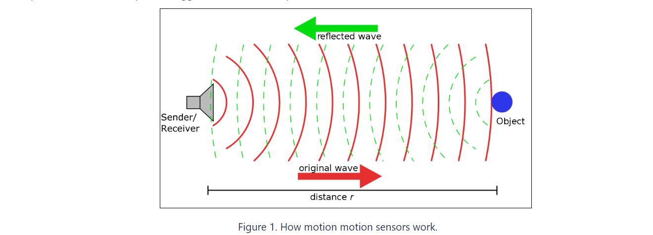
The RCWL-0516 module uses a type of radar called "Doppler Radar" to detect motion and activate proximity alerts. This radar works by emitting a microwave signal toward a target, then measuring the frequency of the signal that bounces back. By analyzing how the target's movement has affected the frequency of the returned signal.
A sensor's response can be measured using an OSCILLOSCOPE, which observes the waves or pulses generated when the sensor detects moving objects and triggers a pulse. When a high wave appears, it indicates that movement has been detected, while a low wave indicates no movement. This digital input provides logic-level information in the form of high and low signals.
Using the RCWL-0516 Sensor as a Standalone Unit we did an experiment based in this example web page, that does not requires a microcontroller or board for it, just a bread board.
Setting up the experiment requires only a few simple steps. We connected the Power supply bench to the sensor'sVIN and GND. Then, connected a small red LED to the output pin, ensuring that a 220Ω current limiting resistor is also included in the circuit. Then we connected a cable Jumper from the output pin to the Oscilloscope through a Probe set that had a Ground connection.

By observing the oscilloscope, we could see the pulses generated when movement was detected. A high pulse indicated that movement had been detected, while a low pulse indicated the absence of movement. Typically, the high pulse lasted for 2 seconds before transitioning to low, unless continuous movement was detected.


POTENTIOMETER, ANALOG INPUT
To detect the analog signal, we assembled a simple potentiometer circuit using the microcontroller board of one of our team member, Bartholomew Ting

Below was the sketch that we used:
#includeServo myservo; // create servo object to control a servo int potpin = D0; // analog pin used to connect the potentiometer int val; // variable to read the value from the analog pin int val1; int val2; int servo = D4; // D0 to D9 are PWM pins, D10 is NOT PWM pin int servo2 = D5; // void setup() { Serial.begin(9600); myservo.attach(servo,500,2400); myservo2.attach(servo2,500,2400); // attaches the servo on pin (servo2) D9 to the servo object, min pulse width, max pulse width // min (optional): the pulse width, in microseconds, corresponding to the minimum (0 degree) angle on the servo (defaults to 544) // max (optional): the pulse width, in microseconds, corresponding to the maximum (180 degree) angle on the servo (defaults to 2400) } void loop() { val = analogRead(potpin); // reads the value of the potentiometer (value between 0 and 1023) Serial.println(val); val1 = map(val, 0, 1023, 100, 30); // scale it to use it with the servo (value between 30 and 100 degree) val2 = map(val, 0, 1023, 30, 100); myservo.write(val1); myservo2.write(val2); // sets the servo2 position according to the scaled value delay(15); // waits for the servo to get there }
We connected the signal pin of the potentiometer to pin D0 of the microcontroller board. We then connect two servo motors to pin D4 and D5 resepctively (the D4 servo is attached to the mouth of the cardboard panda while the D5 servo is attached to the arm). The microcontroller will read the analog signal from the potentiometer at D0 and mapped it to the servo motors accordingly. We also hooked up D0 to the oscilloscope to observe the signal received.
We then powered the circuit and can observed from the oscilloscope the analog signal changing according to the turning of the potentiometer. We also observed thatthe servo motors moved according to the signal received at D0: when the signal was at the minimum, D4 servo was at maximum angle 100° (i.e., panda's mouth was closed) and D5 servo was at minimum angle 30° (i.e., panda's arm was lowered). As the signal increased to the maximum, D4 servo's angle value started to decrease to the minimum angle 30° (i.e., panda's mouth gradually closed), while D5 servo's angle value gradually increased to the maximum 100°(i.e., the panda's arm gradually went up):
The observation was consistent with the sketch.