Week 13: Networking and Communications
Assignments
The assigments for this week are:Group Assignment
Send a message between two projects
Individual Assignment
Design, build, and connect wired or wireless node(s) with network or bus addresses
Group Assignment
For this week's group assigment, we were supposed to send a message between two projects. Therefore, we attempted to establish an I2C Bus Communication between us by using Arduino UNO Microcontrollers. Together with the rest of the team, I helped set up the initial network circuit and was doing some of the troubleshooting. After some hiccups, we eventually got the network to work. This is my first time setting up a network circuit and I find it an interesting experience. Full documentation can be found on the group assignment page.Individual Assignment
Using the experience from the group assignment, I decided to use the same Instructables project that we used for the group assignment for my individual assignment. In my case, I initially planned to send a message between the Xiao board I fabricated during electronics production week and the board I fabricated for my final project.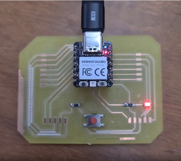
Details
Basically, the project involves setting up an I2C bus between two boards. One will be the main board, while the other board will be the peripheral board. An instruction will be keyed in via the serial monitor to the main board, which will then send a message to the peripheral board to switch an LED connected to it on or off.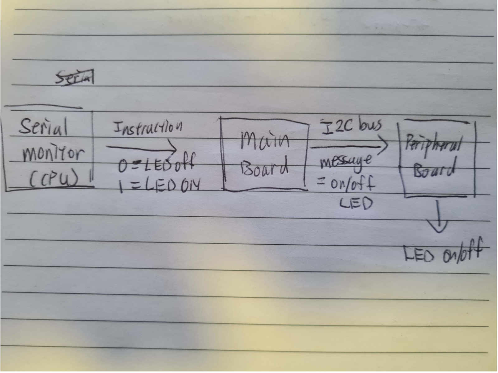 The code for the main board is as below:
#include <Wire.h>
String readString;
byte I2C_OnOff;
void setup()
{
  Wire.begin();
  Serial.begin(9600);
  Serial.println("Type On to turn on the LED and Off to shut it down!");
}
void loop()
{
  while (Serial.available())
  {
    delay(2);
    char c = Serial.read();
    readString += c;
  }
  if (readString == "BlueOn" or readString == "BLUEON" or readString == "blueon")
  {
    I2C_OnOff = 1;
  }
  else if (readString == "BlueOff" or readString == "BLUEOFF" or readString == "blueoff")
  {
    I2C_OnOff = 0;
  }
  if (readString.length() > 0)
  {
    Serial.println(readString);
    readString = "";
  }
  Wire.beginTransmission(1);
  Wire.write(I2C_OnOff);
  Wire.endTransmission();
}
The code for the peripheral board is as below:
#include <Wire.h>
int DO_Blink = 13;
byte I2C_OnOff;
void setup()
{
  pinMode(DO_Blink, OUTPUT);
  Wire.begin(1);
  Wire.onReceive(BlinkLED);
}
void loop()
{
delay(100);
}
void BlinkLED(int Press)
{
  I2C_OnOff = Wire.read();
  if (I2C_OnOff == 1)
  {
   digitalWrite(DO_Blink, HIGH);
  }
  else if (I2C_OnOff == 0)
  {
   digitalWrite(DO_Blink, LOW);
  }
}
Issues
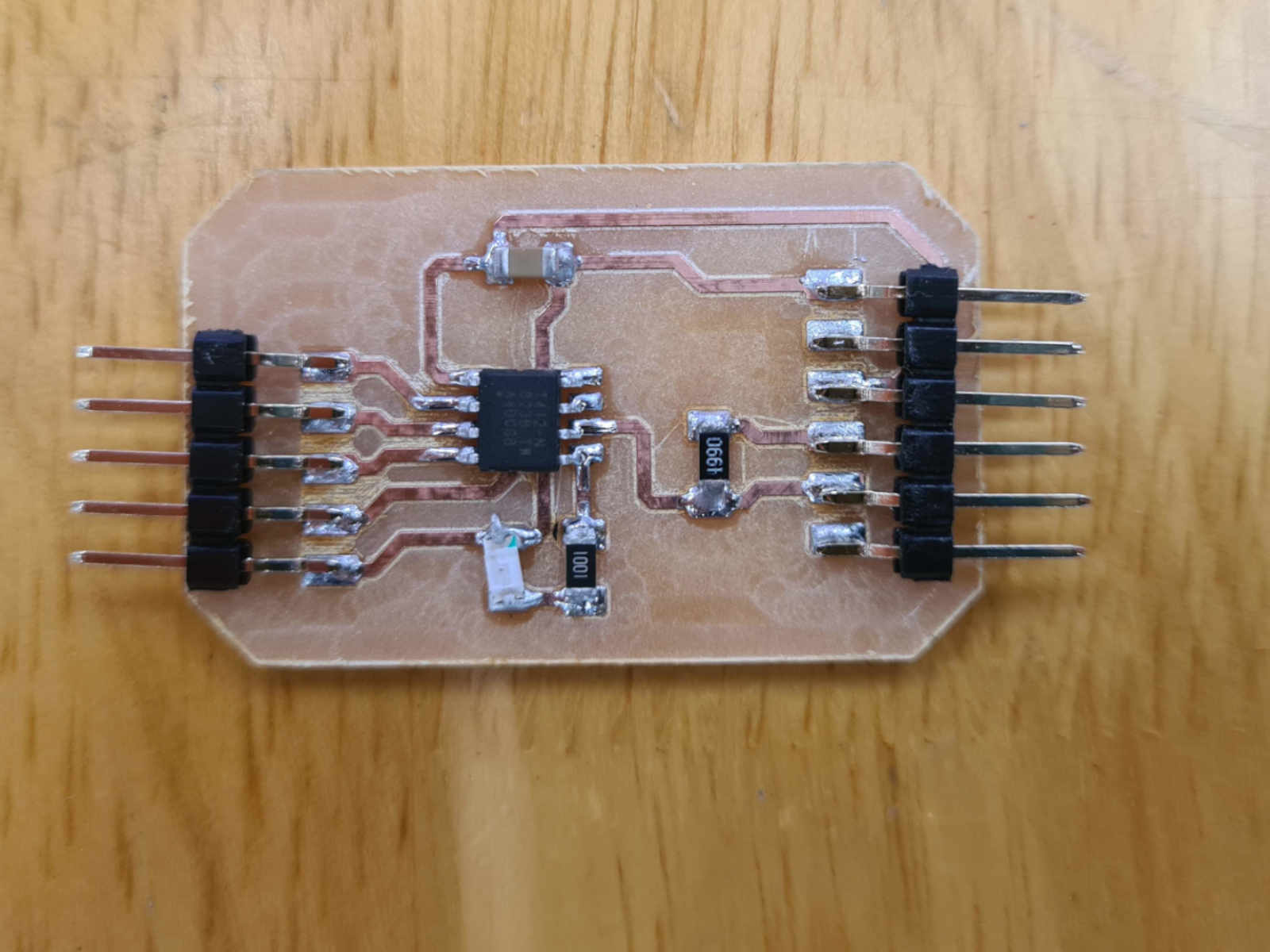
I encountered a few hiccups for this project. The first hiccup was that I found out my final project board could not be used to set up the I2C bus required as I did not pin out the SCL pin. Therefore, I fabricated a network board, which pinned out both the SDA and SCL pin. I also included the pull-up resistors for the I2C bus into the circuit.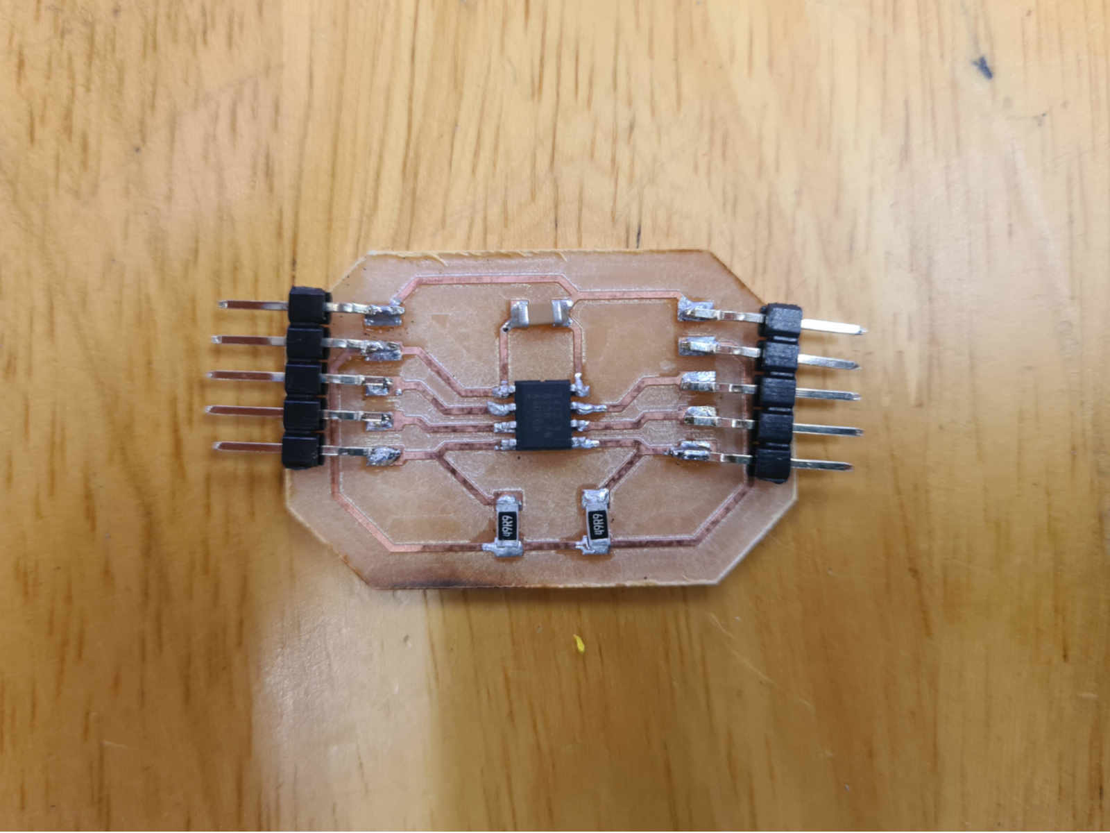 Using the new network board and the Xiao board, I setup the the boards according to the instructions, but still I was unable to send a message from the Xiao board (as the main board)
to the network board (as the peripheral board). I thought it might be a hardware issue since my course mate Juliana
succeeded by following the same instructions with her boards. However, I checked my board - and the wires - and found no issues.
I tried changing the boards - including connecting to the Xiao directly and using a Arduino Nano - and switching the main/peripheral rolea around between the boards,
but I still was not able to send a message between one board to another.
I then consulted my instructor Steven. He saw that the resistor I used for the I2C bus has too low a value (it should be 4.99K Ohm instead of 4.99 Ohm). This is the third hiccup for this assignment.
I immediately changed the resistors to the correct value.
Using the new network board and the Xiao board, I setup the the boards according to the instructions, but still I was unable to send a message from the Xiao board (as the main board)
to the network board (as the peripheral board). I thought it might be a hardware issue since my course mate Juliana
succeeded by following the same instructions with her boards. However, I checked my board - and the wires - and found no issues.
I tried changing the boards - including connecting to the Xiao directly and using a Arduino Nano - and switching the main/peripheral rolea around between the boards,
but I still was not able to send a message between one board to another.
I then consulted my instructor Steven. He saw that the resistor I used for the I2C bus has too low a value (it should be 4.99K Ohm instead of 4.99 Ohm). This is the third hiccup for this assignment.
I immediately changed the resistors to the correct value.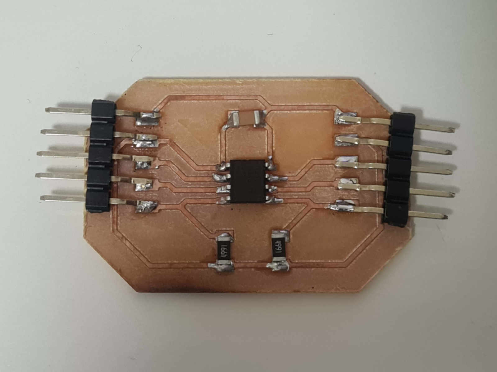 With the resistors changed, I tried to network the boards again. However, I was still unable to send a message through the boards.
Solution
Finally, the breakthrough came when I fiddled with the code. I decided to directly investigate whether the I2C bus is working, so instead of reading the value from the serial monitor for the wire.read() function, I wrote the value directly into function for the main board to send (i.e. writing wire.read(1), where 1 is the to turn on the LED at the peripheral board). To my relief, the LED lit up. So from this I knew the I2C bus was working, and there might be some issue with the serial monitor. To further confirm the issue was with the serial monitor, I added a serial.println(I2C_OnOff) function to the code to read the serial monitor. The printout was only showing 0 (the value to turn off the LED) and didn't change to 1 even when I typed the instruction to do so.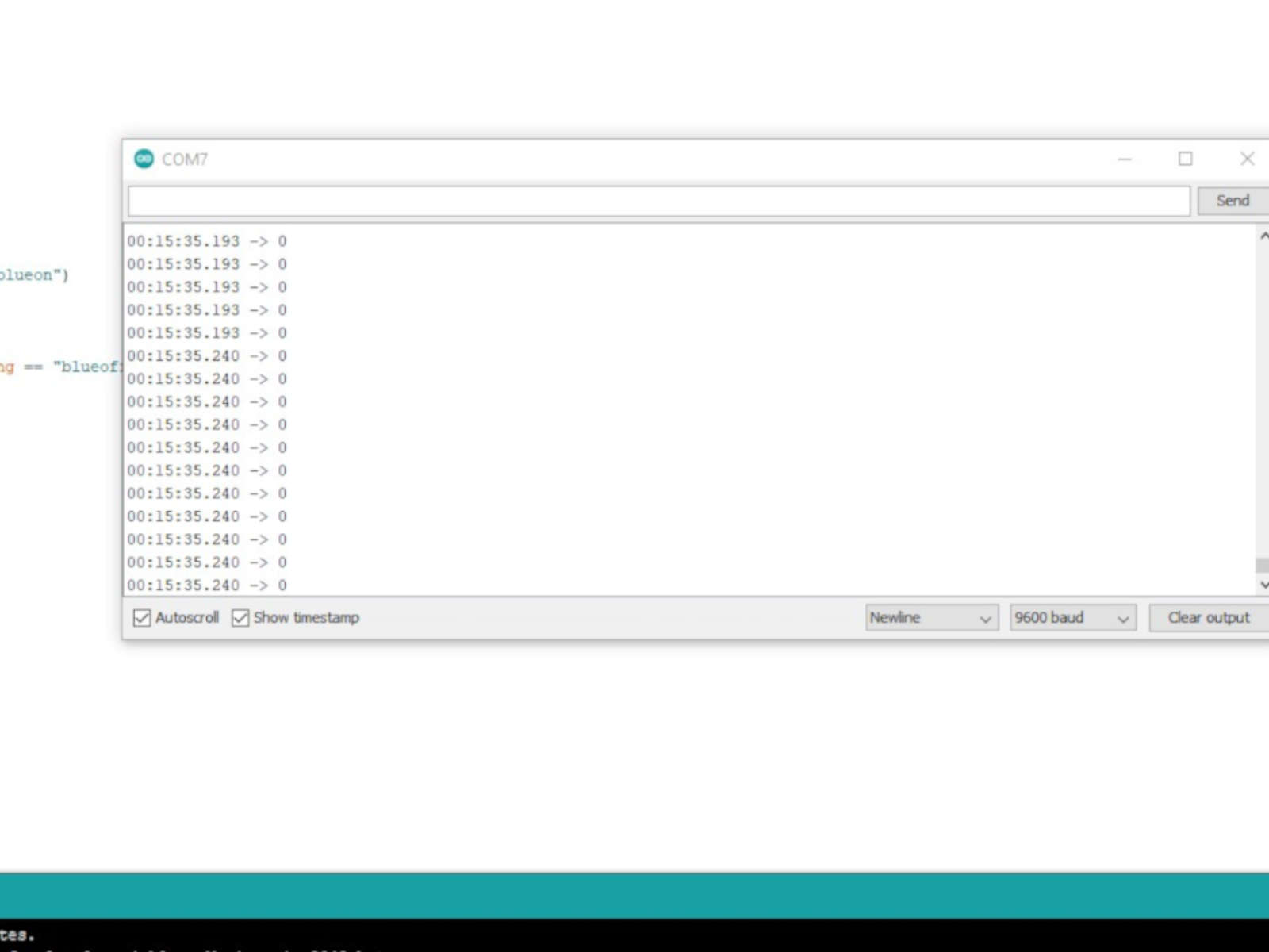 So I decided to modify the code for the main board and changed the input device from the serial monitor to simply shorting two jumper wires. This time round, the message to control the LED was sent through.
The boards I eventually used to set up the network are the Arduino Nano (main) and my network board (peripheral). The modified code had the serial monitor section replaced by the code I used for the input device week. The code for the peripheral board remained the same.
#include <Wire.h>
String readString;
byte I2C_OnOff;
int read_high;
int read_low;
int diff;

void setup()
{
  Wire.begin();
  Serial.begin(9600);
  Serial.println;
  pinMode(10,OUTPUT);
}
void loop()
{
   digitalWrite(10,HIGH);              //Step the voltage high on conductor 1.
   read_high = analogRead(A6);        //Measure response of conductor 2.
   delayMicroseconds(100);            //Delay to reach steady state.
   digitalWrite(10,LOW);               //Step the voltage to zero on conductor 1.
   read_low = analogRead(A6);         //Measure response of conductor 2.
   diff = read_high - read_low;       //desired answer is the difference between high and low.


  delay(100);

  if (diff > 500){
    I2C_OnOff =1;
  }
  else {
    I2C_OnOff =0;
  }

  Wire.beginTransmission(1);
  Wire.write(I2C_OnOff);
  Wire.endTransmission();
  Serial.println(I2C_OnOff);

}
Conclusion
There are a couple of learning points from this week’s assignment. Beside learning about networking, I had also learned a lesson on troubleshooting. It is important to approach troubleshooting in a more organised manner and to try and isolate the different part of the system as much as possible to test and troubleshoot. That way, a lot of time can be saved.Design files
Document files related to the network board. (Includes .brd, .png, .dxf)Source codes for the main board (both original and modified) and the peripheral board.