Final Project
Initial Research
I gathered some relevant information for my final project from the following sources:Observation and internet search on commercial PMDs
From here I found out about the differnt types of PMDs (e.g. electric scooter, electric wheelchairs, hoeverboard, etc.) and how they work. I also found out about the parts and technical specifications of the PMDs. DIY Electric Powered Wheelchair
This project on Instructables has clear documentation, except the electronics and programming part is missing.
The electric wheelchair being built here was made of metal beams and machined parts.
The wheelchair was controlled by joystick
The motor used was 24V DC brushed motor Open Wheel Chair
This website provides instructions (and some parts) for building electric wheelchair for children using PVC pipes.
The wheelchair was controlled by joystick
The motor used was 12V DC motor.
An experimental prototype electronics board was used to control the wheelchair Press Fit Go Kart
This project is from the 2014 class of the How To Make (almost) Anything class at MIT's CBA, which the Fab Academy is based on.
The go kart chassis was made from plywood and assembled together with press fit joints.
The go kart was controlled by an improvised steering mechanism.
The wheels were chain driven by two 24V DC motor using commercially available controller.
Electronics for monitoring the battery pack voltage were added.
Design
My first idea is a basic design of a box with 4 wheels, with the PMD control by foot pedals, as described in week 1 assignment.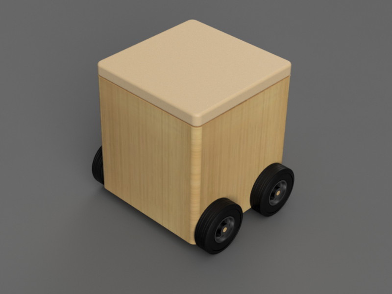 This first idea was more of a conceptual design, so it did not factor in much technical details such as the drive system, the positioning of the motors, or even the dimensions.
Upon further research, I came up with a 2nd design:
This first idea was more of a conceptual design, so it did not factor in much technical details such as the drive system, the positioning of the motors, or even the dimensions.
Upon further research, I came up with a 2nd design:
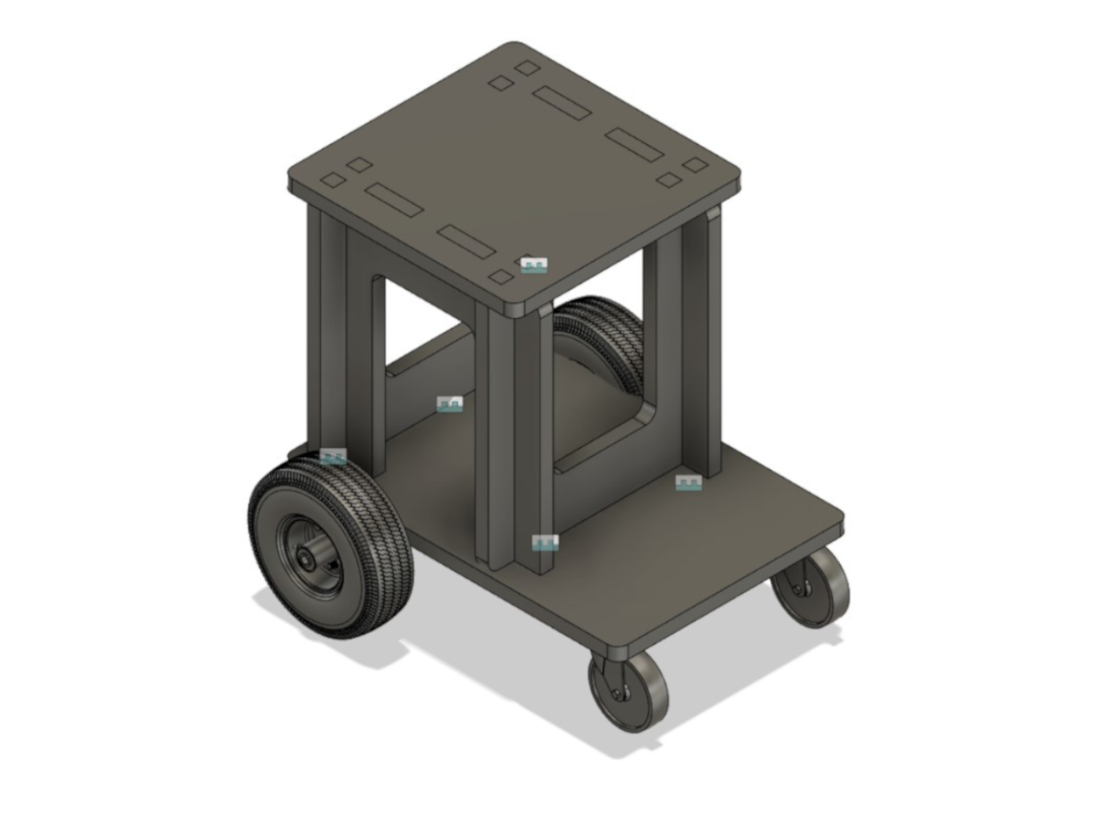 The 2nd design came about after the overall dimensions were taken into account, as well as the size of the main parts (e.g. the motors and the wheels).
As the compactness of the design was the top priority for me, I decided to forgo the storage space and had the motors and battery unit fit underneath the seat.
For the chassis, as I had some success with press fit joints during the Computer Controlled Machining week,
I decided to keep with a press fit design and took reference from Ajith Kumar M G's design
from the 2017's class of Fab Academy.
As for the navigation, the initial idea was to do it by differing the speed and direction of the two rear wheels - i.e., to move left, the right wheel moves faster/forward, while the left wheel moves slower/backward, and vice
versa for moving right. To achieve this, there will be two foot pedals, each controlling the speed and direction of the a wheel.
However, upon further discussion with instructor Steven, I found that controlling direction of the PMD this way might be too challenging. Therefore, I decided to make a modification to the design by adding a handlebar and
changing the PMD from having 4 wheels to 3 wheels, with a single wheel at the front.
The 2nd design came about after the overall dimensions were taken into account, as well as the size of the main parts (e.g. the motors and the wheels).
As the compactness of the design was the top priority for me, I decided to forgo the storage space and had the motors and battery unit fit underneath the seat.
For the chassis, as I had some success with press fit joints during the Computer Controlled Machining week,
I decided to keep with a press fit design and took reference from Ajith Kumar M G's design
from the 2017's class of Fab Academy.
As for the navigation, the initial idea was to do it by differing the speed and direction of the two rear wheels - i.e., to move left, the right wheel moves faster/forward, while the left wheel moves slower/backward, and vice
versa for moving right. To achieve this, there will be two foot pedals, each controlling the speed and direction of the a wheel.
However, upon further discussion with instructor Steven, I found that controlling direction of the PMD this way might be too challenging. Therefore, I decided to make a modification to the design by adding a handlebar and
changing the PMD from having 4 wheels to 3 wheels, with a single wheel at the front.
Fabrication
Material
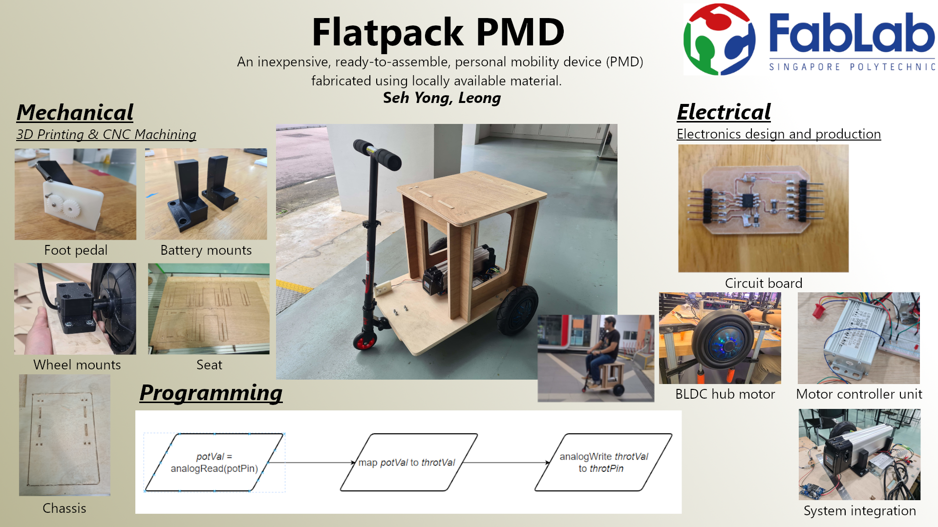
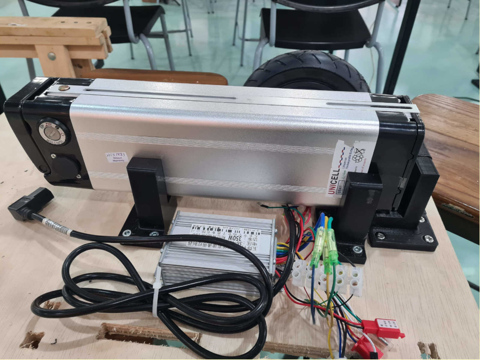
The bill of material were mentioned in the assignment for Application and Implication week. The original plan was to use DC brushed motors for the PMD. However, due to issues with the oversea supplier, I had to switch to brushless DC (BLDC) hub motor at the late stage of development. Fortunately, the PMD design is flexible enough to accommodate the change in the type of motor used. Additonally, since the BLDC hub motors are on the wheels, there was no longer a need to factor in space on the chassis to install the motors. This allows the PMD to be remain compact while affording more allowance to install other parts and components on the chassis.Electronics
The electronic circuit of the PMD were wired according to this schematic: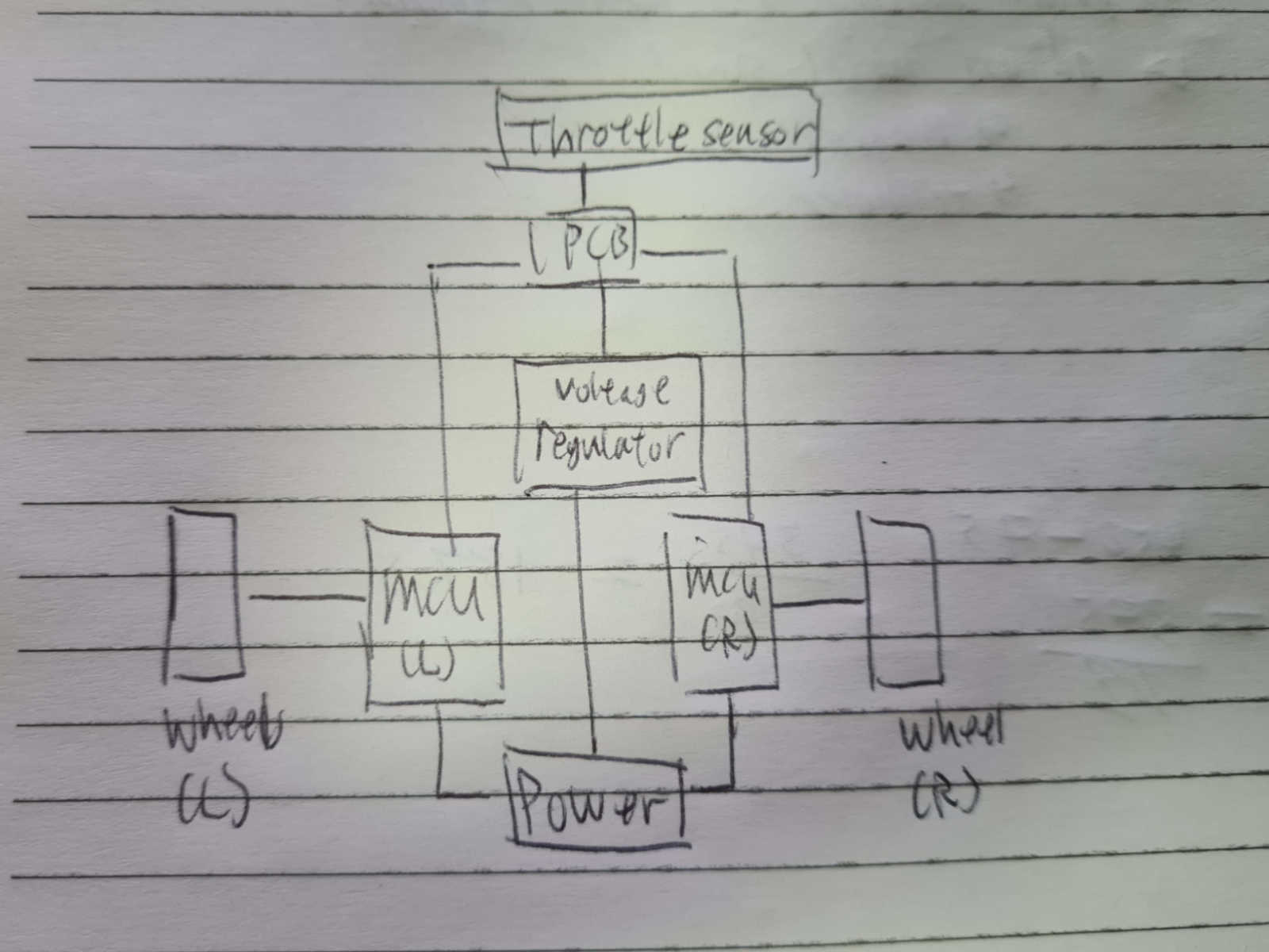 Basically, the battery power was connected to two motor controller units (MCUs) and a voltage regulator. Each MCU was then connected to a BLDC hub motor wheel, while the voltage regulator was connected to the circuit board.
The circuit board controls the throttling of the wheels by being connected to a sensor and the MCUs.
Circuit board
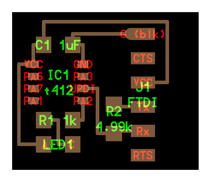
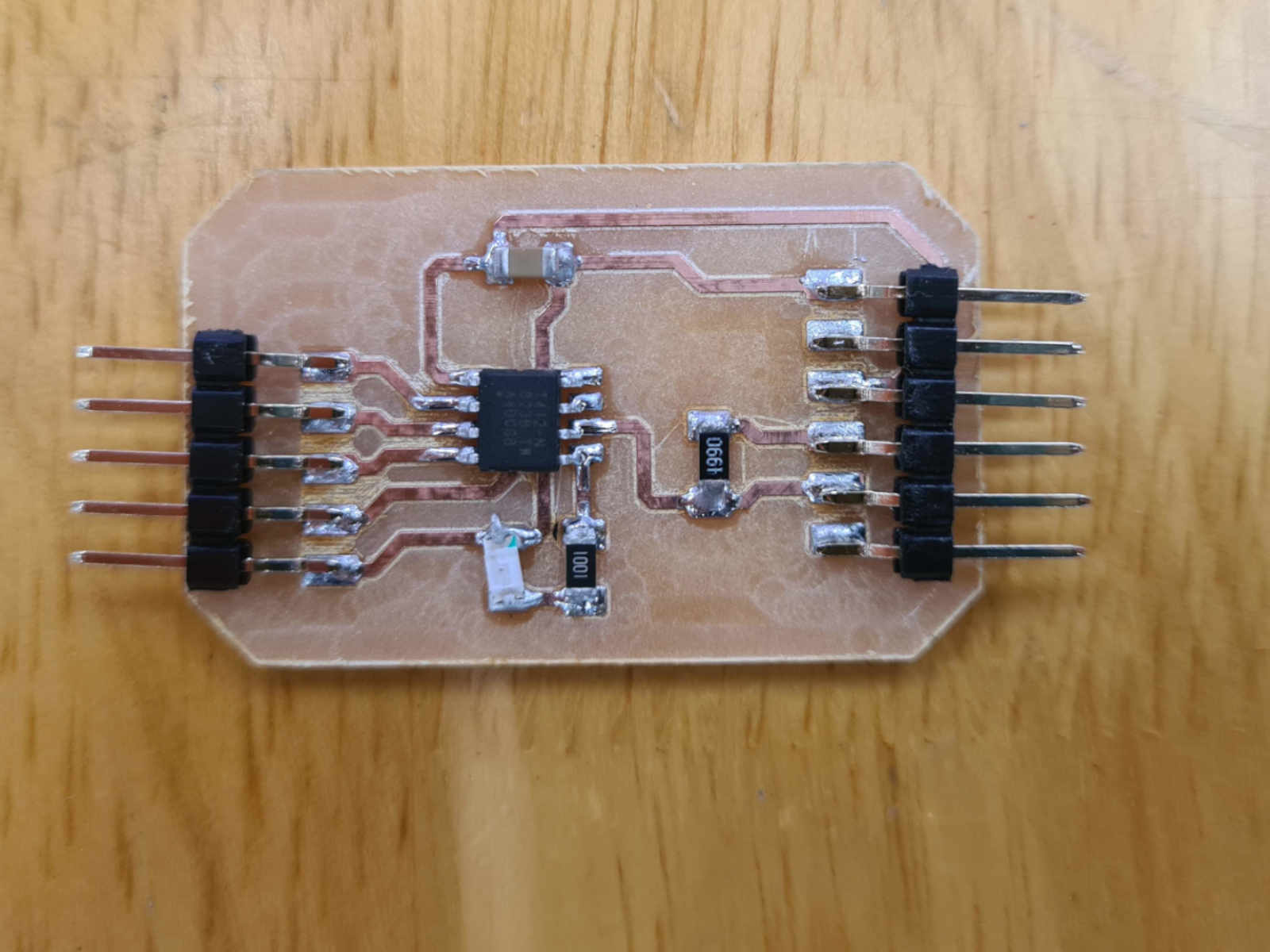
The design of the board was based on the Neil's AtTiny412 blink-2 pin board..
The difference is that I pinned out 3 of the pins. The original intention is to use PA6 sensor as the sensor pin as it has a DAC (digital to analog converter).
Basically, the battery power was connected to two motor controller units (MCUs) and a voltage regulator. Each MCU was then connected to a BLDC hub motor wheel, while the voltage regulator was connected to the circuit board.
The circuit board controls the throttling of the wheels by being connected to a sensor and the MCUs.
Circuit board
The design of the board was based on the Neil's AtTiny412 blink-2 pin board..
The difference is that I pinned out 3 of the pins. The original intention is to use PA6 sensor as the sensor pin as it has a DAC (digital to analog converter).
 Sensors
With the throttle being controlled electronically by the circuit board, it is possible to use a wide range of sensors. However, as a first model, I decided to stick to the potentiometer as it is simple to implement.
Testing The Wheels
The BLDC hub motor wheels are the key parts of the project. Therefore, it is the first to be tested to make sure it works.
The wiring of the BLDC to the MCU is shown in the diagram below.
Sensors
With the throttle being controlled electronically by the circuit board, it is possible to use a wide range of sensors. However, as a first model, I decided to stick to the potentiometer as it is simple to implement.
Testing The Wheels
The BLDC hub motor wheels are the key parts of the project. Therefore, it is the first to be tested to make sure it works.
The wiring of the BLDC to the MCU is shown in the diagram below.
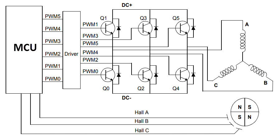
Photo from Electronics Hub As shown in the diagram, A, B and C are the coils, or phase, of the BLDC motor. When current are applied to these coils, it will generate a magnetic field that will rotate the rotor (which is a permanent magnet), thus turning the motor. Thus, there are three phase wires coming out of the motor for the stators. Each wire will be connect to two of the six MOSFET (Q0 to Q5) in the MCU. By activating the appropirate MOSFET, the MCU can control the movement and speed of the motor. To determine exactly which MOSFET to activate, the Hall effect sensors (Hall A, B, C), which are embedded in the stators and 120° apart fromeach other, are wired to the MCU as well. First, the three phase wires from the wheels are connected to the MCU. The order or sequence of connection is not important here.
 Then, the Hall effect sensor wires were connected. In this case there are fivce wires, with the red wire for power, black wire for GND.
Exepct for the red and black wires, which must be connected accordingly, there is no specific order or sequence of connection for the remaing 3 wires of the hall-effect sensors.
Then, the Hall effect sensor wires were connected. In this case there are fivce wires, with the red wire for power, black wire for GND.
Exepct for the red and black wires, which must be connected accordingly, there is no specific order or sequence of connection for the remaing 3 wires of the hall-effect sensors.
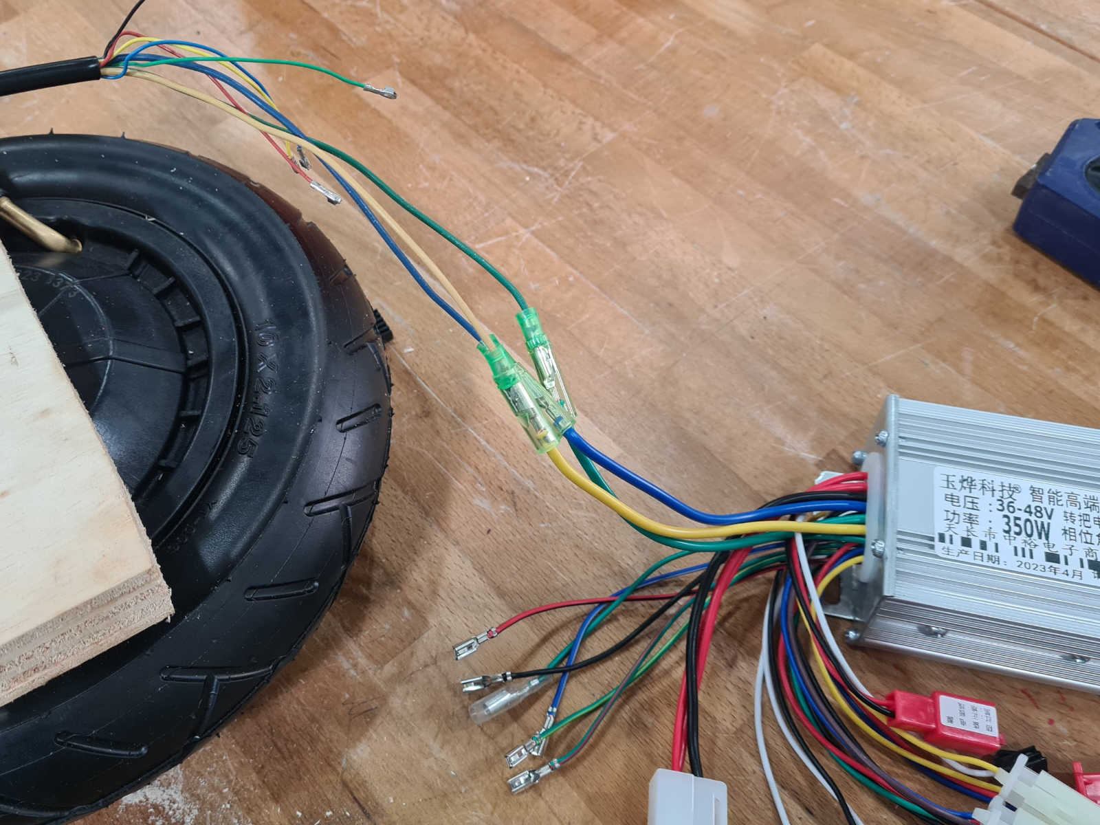
 I began by testing one of the wheels by wiring it and a hand throttle to the MCU. The expected outcome was that the hand throttle will control the turning speed of the wheel. However, this was not the case as the wheel
did not turn at all.
I began by testing one of the wheels by wiring it and a hand throttle to the MCU. The expected outcome was that the hand throttle will control the turning speed of the wheel. However, this was not the case as the wheel
did not turn at all.
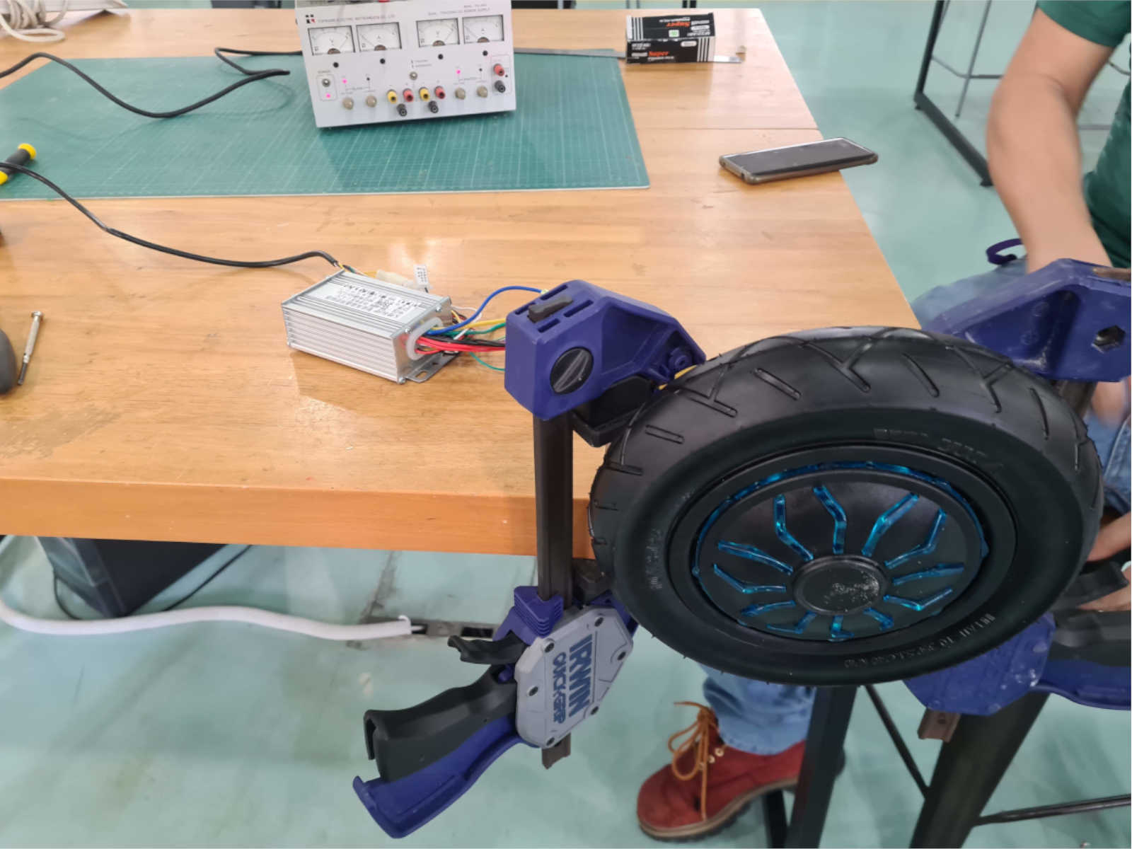 The BLDC wheel was rated 36V and it was supplied with 30V from a power supply. It was observed there was there were no current when the power supply was switched on, suggesting that the circuit was not drawing any power.
After trying out a a few possiblities, the breakthrough came when the the learning wires on the MCU were connected. The learning wires are used to set the turning direction of the wheel and when it was connected, the wheel
started turning.
The BLDC wheel was rated 36V and it was supplied with 30V from a power supply. It was observed there was there were no current when the power supply was switched on, suggesting that the circuit was not drawing any power.
After trying out a a few possiblities, the breakthrough came when the the learning wires on the MCU were connected. The learning wires are used to set the turning direction of the wheel and when it was connected, the wheel
started turning.From this we know the wheel was in working order and perhaps the power supplied to it was not enough. Therefore, the supplied power was increased to 36V. This was done by connecting the wheel two both output of the power supply, each supplying 18v. With this incease to 36V, the wheel started turning without issue. Wiring After the first wheel was successfully tested, the second wheel was wired up and connected to the power supply. The wheels were then tested separately.
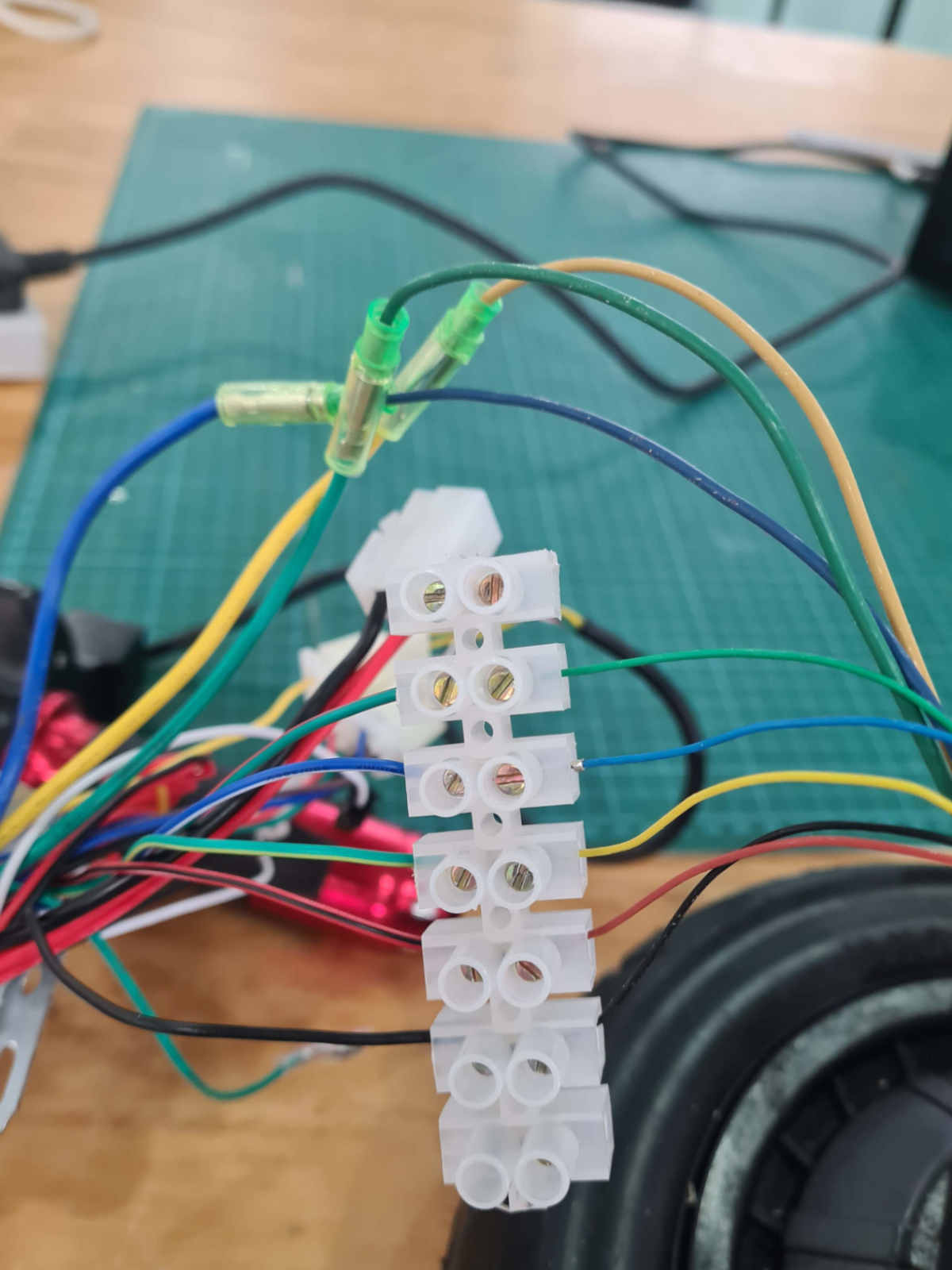
The wheels were powered by a 36V battery, which will be the eventual power source for the PMD. I had also changed the throttle control to the potentiometers, as it made testing of the wheels easier and it was also the sensor that will be used. Next I connected the signal wire of both wires to the same potentiometer, to control both wheels with a single input device: Next I wired the voltage regulator to the power supply and tuned it's output voltage to 5v. The circuit board was then wired to the regulator and tested. Finally, to complete the wiring of the PMD, the potentiometer is connected to the circuit board as the Input device. Wiring complete.
Programming
A simplified of the throttle circuit is as shown below: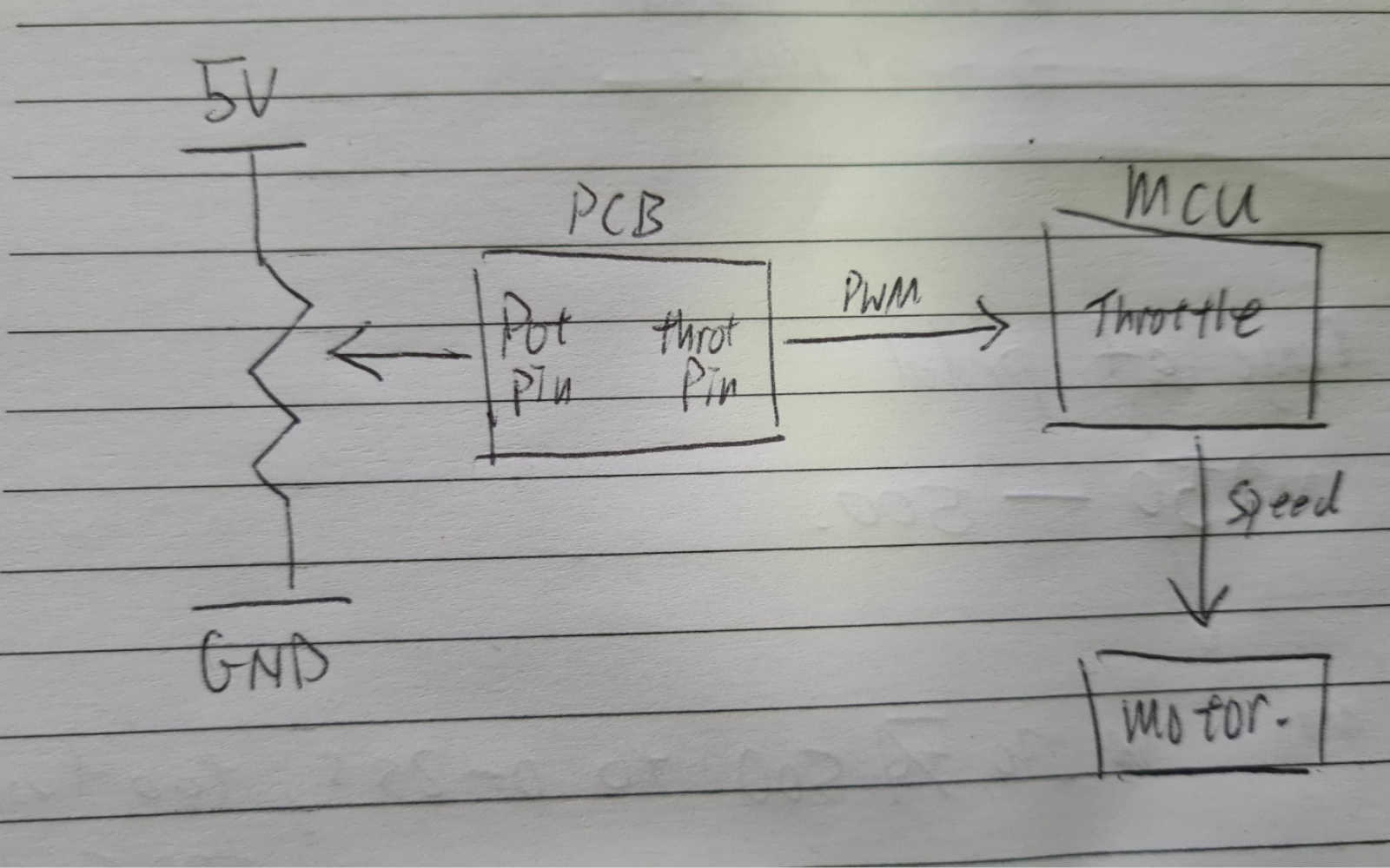 Basically, the circuit board (PCB) will read the voltage value at the potPin of the potentiometer on the right, receiving an input signal between 0 (for 0V reading) and 1024 (for 5V reading).
Based on the value of the input signal received, the board then transmit a corresponding output signal (between 0 to 255) at the throtPin to the MCU, which will in turn control the throttle and thus the speed
at the motor.
To determined the range of output signal (throtVal) to be transmitted by throtPin, I did the following calculation:
Basically, the circuit board (PCB) will read the voltage value at the potPin of the potentiometer on the right, receiving an input signal between 0 (for 0V reading) and 1024 (for 5V reading).
Based on the value of the input signal received, the board then transmit a corresponding output signal (between 0 to 255) at the throtPin to the MCU, which will in turn control the throttle and thus the speed
at the motor.
To determined the range of output signal (throtVal) to be transmitted by throtPin, I did the following calculation:
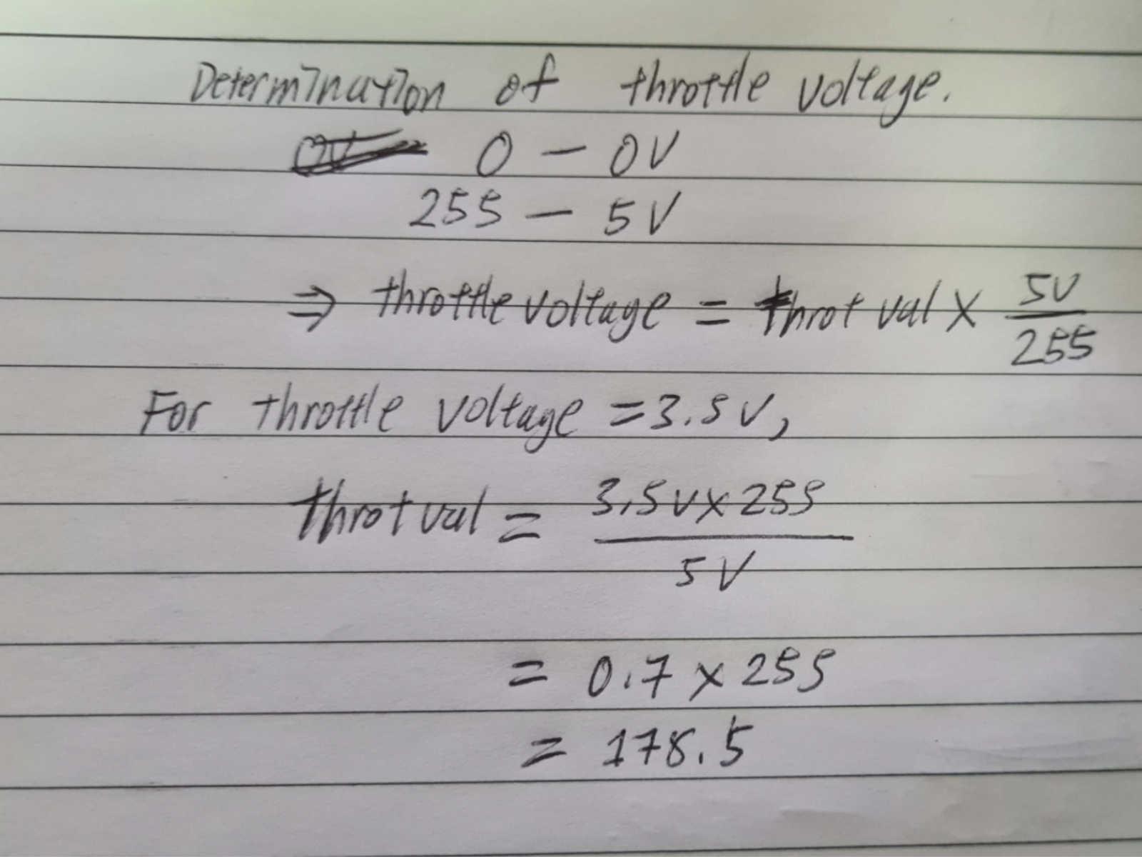 The 3.5V signal was determined during the testing of the wheel. A hand throttle was connected directing to the MCU to control the throttling and at full throttle, the signal at the hand throttle was
measured at 3.5V. Therefore, to control the full range of the throttle, the throtVal need only be between 0 to 178.5.
The board was uploaded with a simple code of mapping the input signal from the potentiometer to the corresponding output
signal (throtVal) to the MCU to turn the wheels at the desired speed.
The 3.5V signal was determined during the testing of the wheel. A hand throttle was connected directing to the MCU to control the throttling and at full throttle, the signal at the hand throttle was
measured at 3.5V. Therefore, to control the full range of the throttle, the throtVal need only be between 0 to 178.5.
The board was uploaded with a simple code of mapping the input signal from the potentiometer to the corresponding output
signal (throtVal) to the MCU to turn the wheels at the desired speed.
int potPin = 2;
int throtPin = 1;
int potVal;
int throtVal;

void setup() {
  pinMode(potPin,INPUT);
  pinMode(throtPin,OUTPUT);
}

void loop() {
  potVal = analogRead(potPin);
  throtVal = map(potVal,0,1024,0,255);
  analogWrite(throtPin,throtVal);

}
Even though throtVal need only to be between 0 to 178.5, I decide to give some allowance and let throtVal to be between 0 and 255.
However, the foot pedal have a limited range of motion and so could only give a small range input value of around 250 units.
Threfore, instead of mapping the full range of 0 to 1024, the code was modified to map the actual input value range to the output values:
int potPin = 2;
int throtPin = 1;
int potVal;
int throtVal;

void setup() {
  pinMode(potPin,INPUT);
  pinMode(throtPin,OUTPUT);
}

void loop() {
  potVal = analogRead(potPin);
  throtVal = map(potVal,400,660,0,255); //mapping the range of input value (potVal) from the pedal to the output value.
  analogWrite(throtPin,throtVal);

}
The actual input range (i.e., 400 to 660) was determined after the foot pedal was mounted onto the PMD.
Mechanical
CNC Machining The chassis and the seat of the PMD were fabricated by large-format machining. As the chassis was the most important piece, it was milled first. With the chassis fabricated, I was able to wired and laid out the electronic components for testing.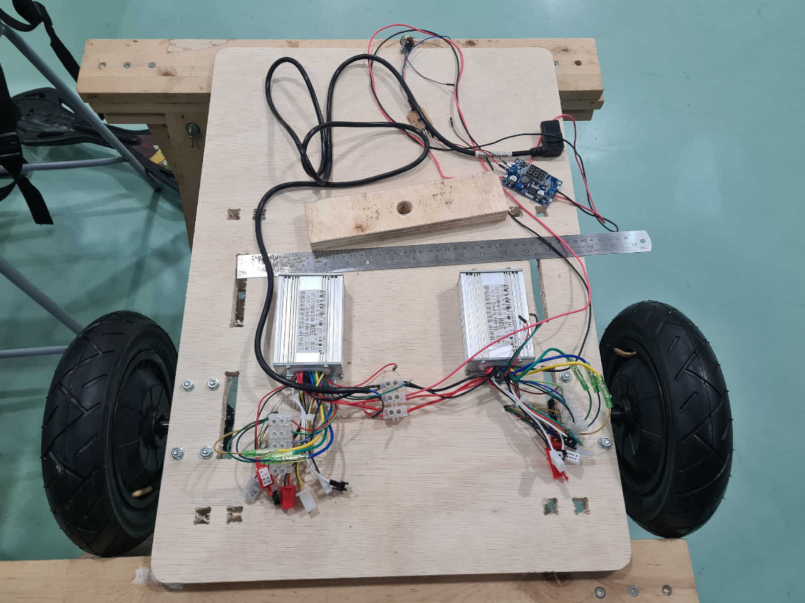 Subsequently the parts for the seats are milled.
3D Printing
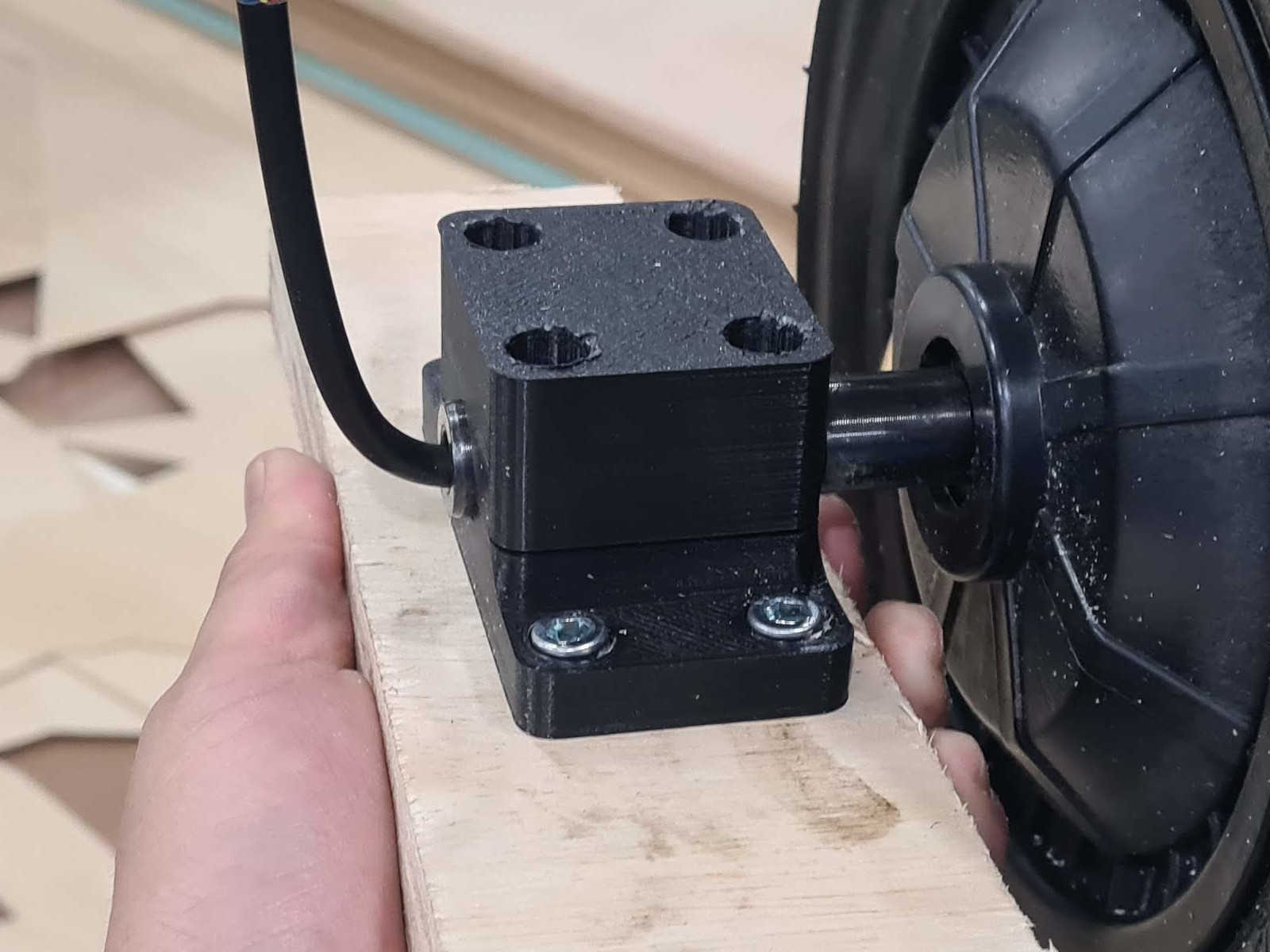
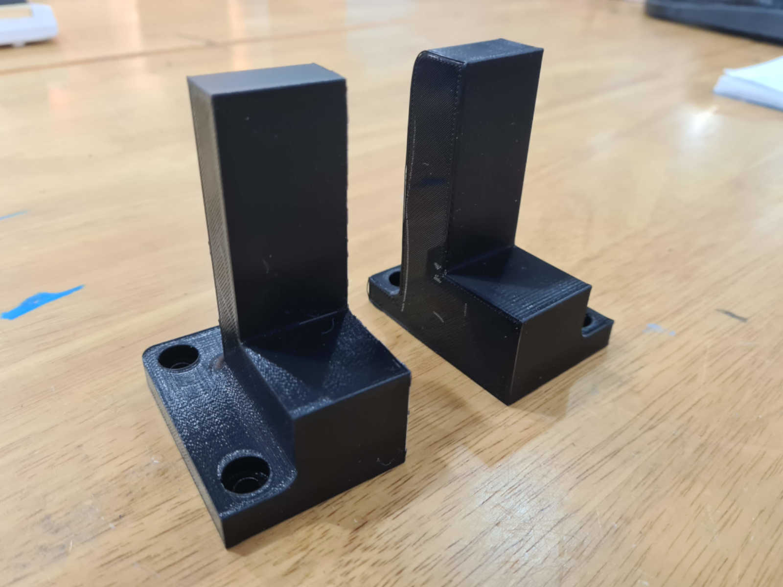
The wheel mount, battery mount and foot pedal were 3D printed.
Subsequently the parts for the seats are milled.
3D Printing
The wheel mount, battery mount and foot pedal were 3D printed.
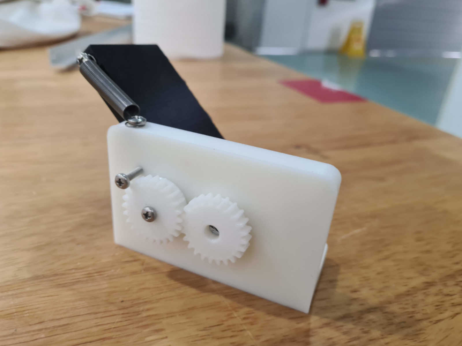 For the design of the foot pedal, I took reference from CadetPedals and Pédale projects on
Thingiverse. The idea was to have a pedal design that can be printed relatively quickly and was small enough to fit to the front foot rest of the PMD. After putting the pedal together, the working parts were found to function
smoothly.
Mounting handlebar
The handlebar was repurposed from an used kick scooter bought from a 2nd hand store.
For the design of the foot pedal, I took reference from CadetPedals and Pédale projects on
Thingiverse. The idea was to have a pedal design that can be printed relatively quickly and was small enough to fit to the front foot rest of the PMD. After putting the pedal together, the working parts were found to function
smoothly.
Mounting handlebar
The handlebar was repurposed from an used kick scooter bought from a 2nd hand store.
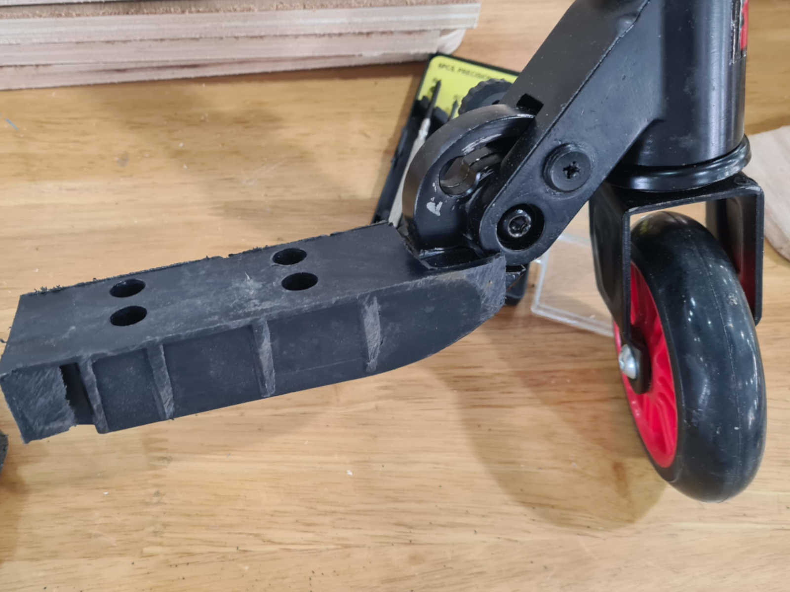
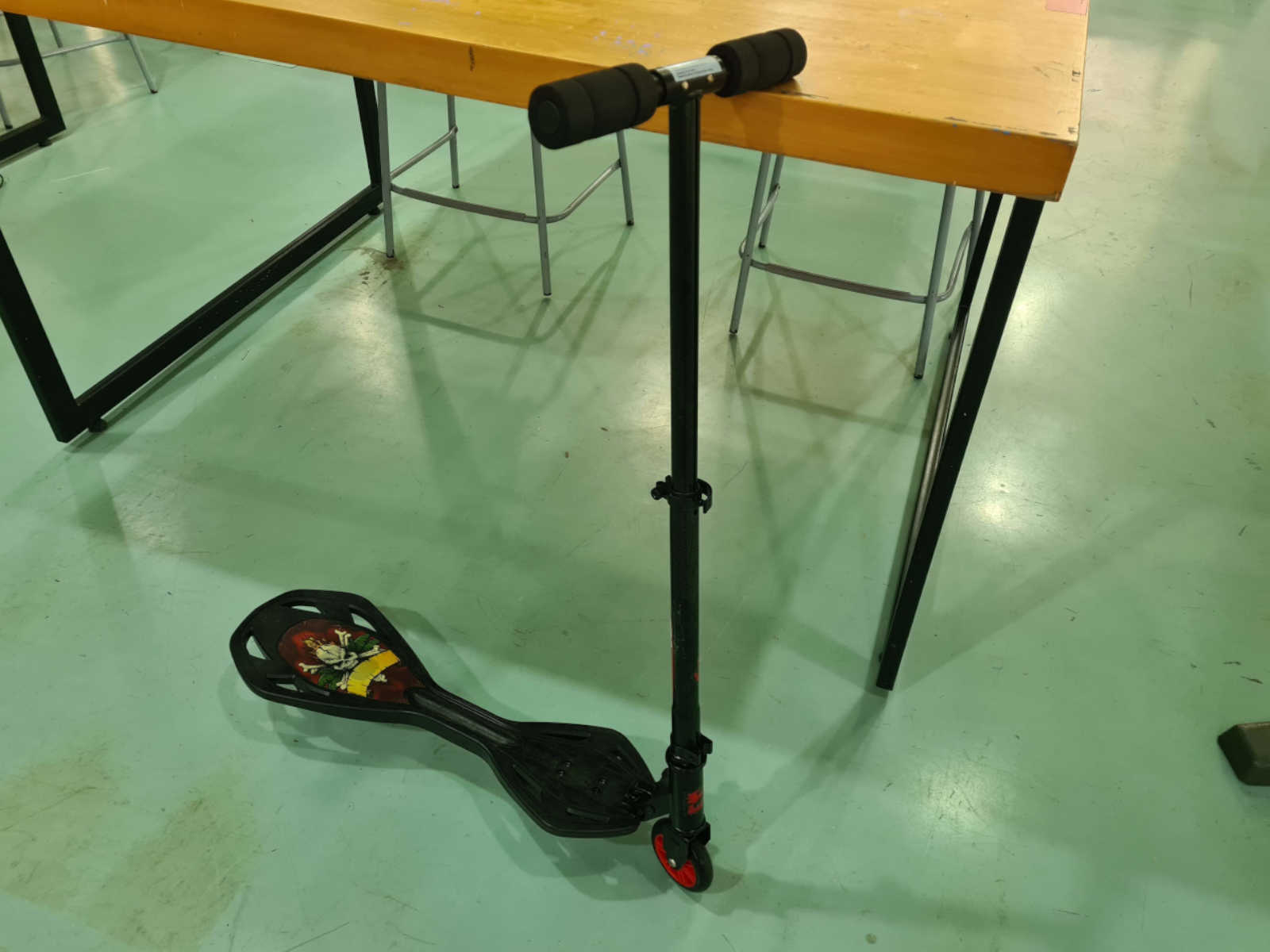 The handlebar was removed from the deck of the kick scooter. Part of the deck was saw off to provide a flat surface to attach to the chassis.
 After attaching the handlebar to the chassis, the whole workpiece was put to a test run.
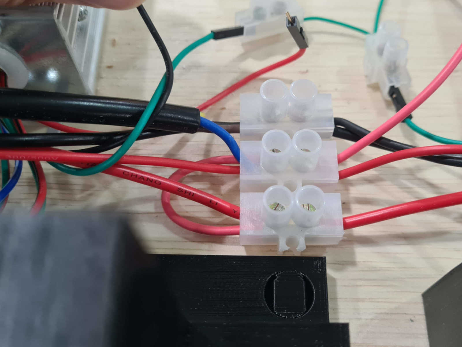
Wire management
Wire connectors were used to connect wires where necessary.
After attaching the handlebar to the chassis, the whole workpiece was put to a test run.
Wire management
Wire connectors were used to connect wires where necessary.
 The wire outlets from the MCU that were not required were tied up with cable ties and put aside.
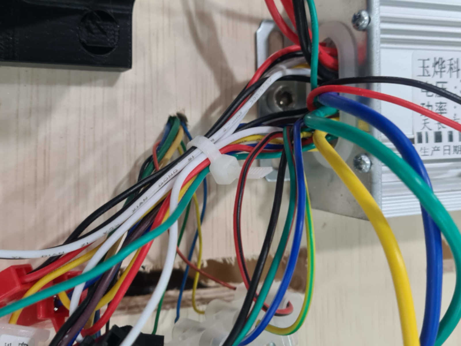 The connected wires were all stowed as tidy as possible between the battery mount, underneath the battery.
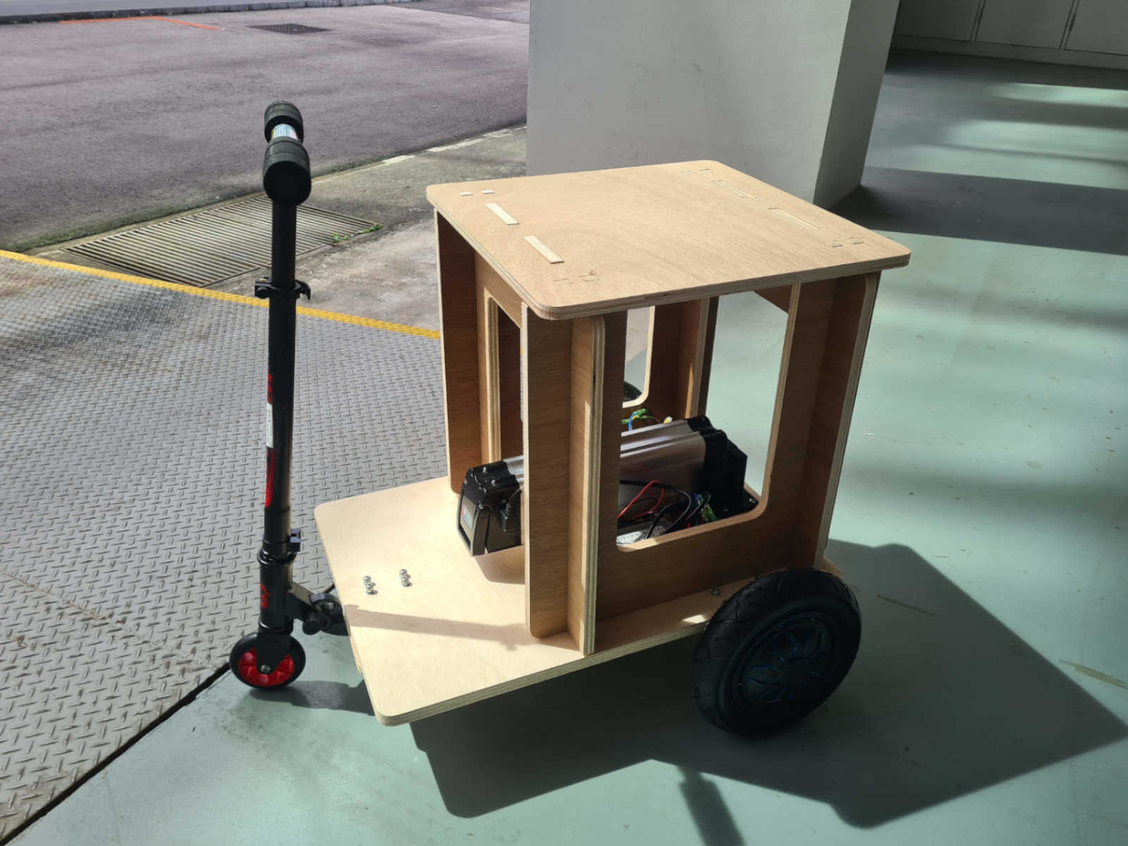
 Final Assembly
Finally, the seat was mounted onto the chassis. The pedal was also installed and connected to the circuit board
This completes the assembly
Final Assembly
Finally, the seat was mounted onto the chassis. The pedal was also installed and connected to the circuit board
This completes the assembly
 Evaluation
The fully assembled PMD was test drived and evaluated. It was able to fulfill the evaluation criteria listed in
Applications and Implication week.
Future action
Further improvement of the PMD will include the following:
- Changing to a more suitable motor controller unit.
- Improving chassis design.
- Controlling the speed and direction using the feet.
Evaluation
The fully assembled PMD was test drived and evaluated. It was able to fulfill the evaluation criteria listed in
Applications and Implication week.
Future action
Further improvement of the PMD will include the following:
- Changing to a more suitable motor controller unit.
- Improving chassis design.
- Controlling the speed and direction using the feet.