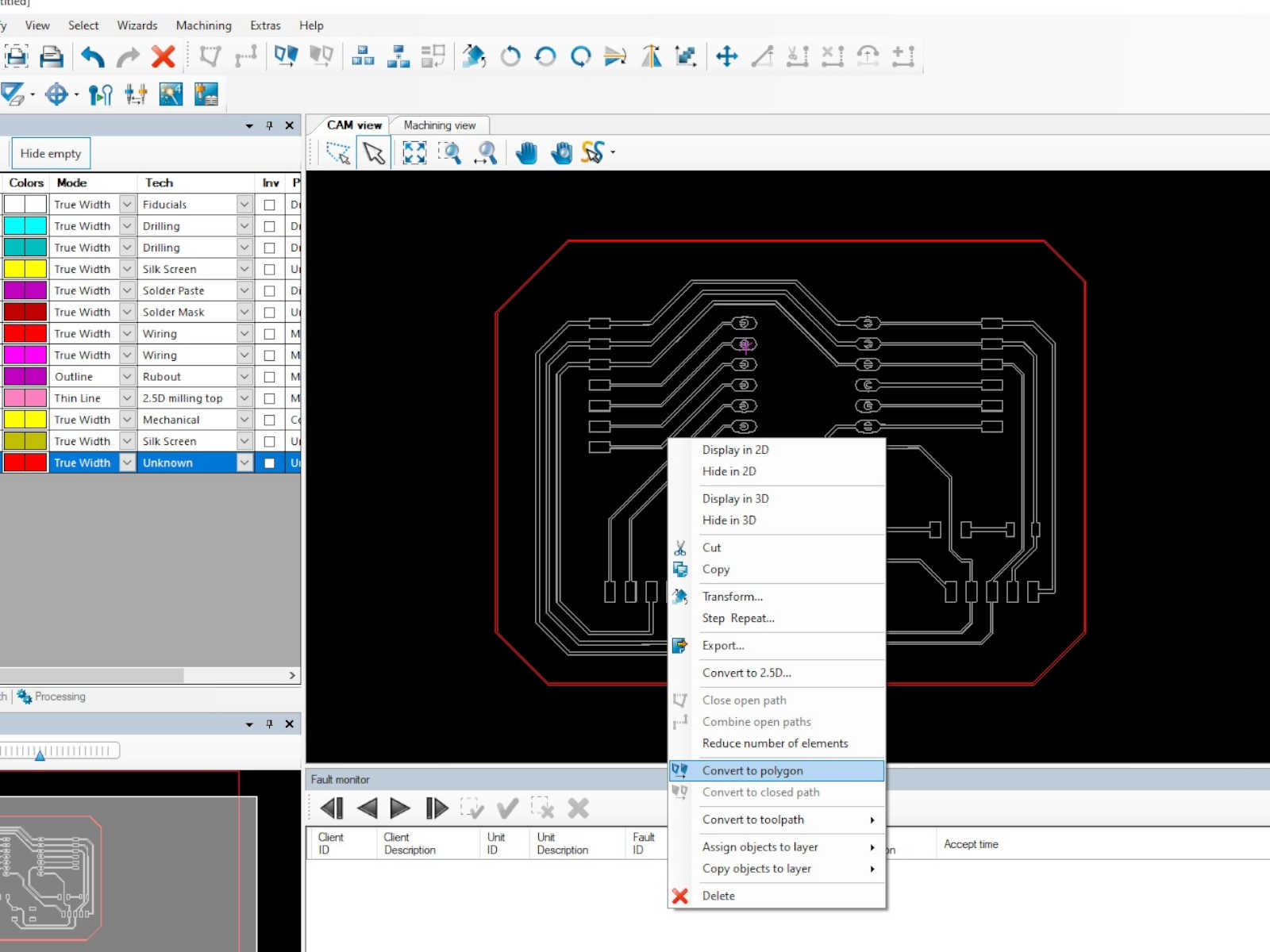
 After the two setps above, the circuit was presented as bold lines.
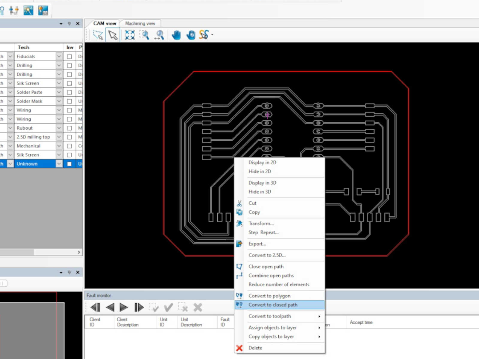
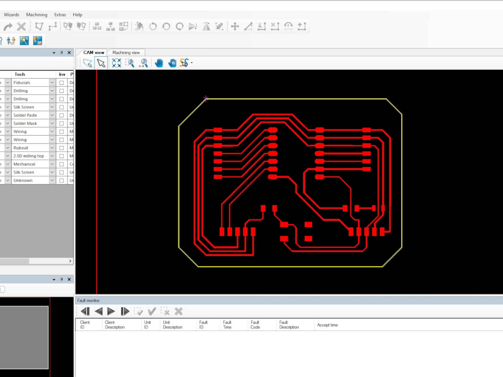
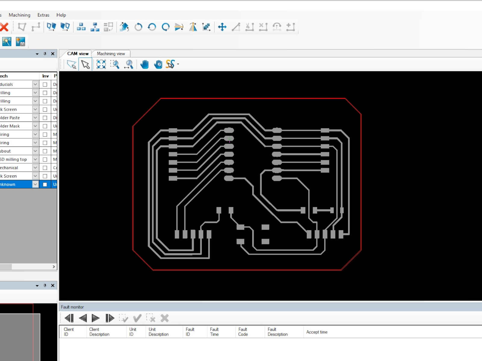 The next step is to select the outline of the circuit and click to select Assign objects to layer > BoardOutline. The outline was then shown as yellow line.
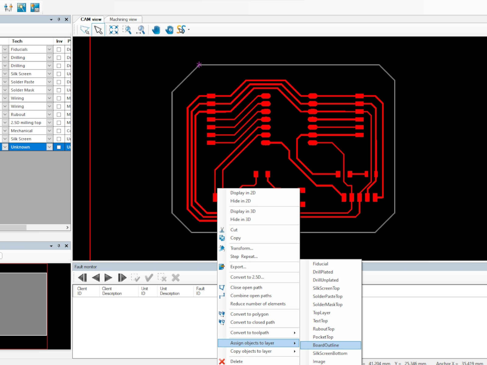
 In the same manner as above, the circuit was assigned the Toplayer.
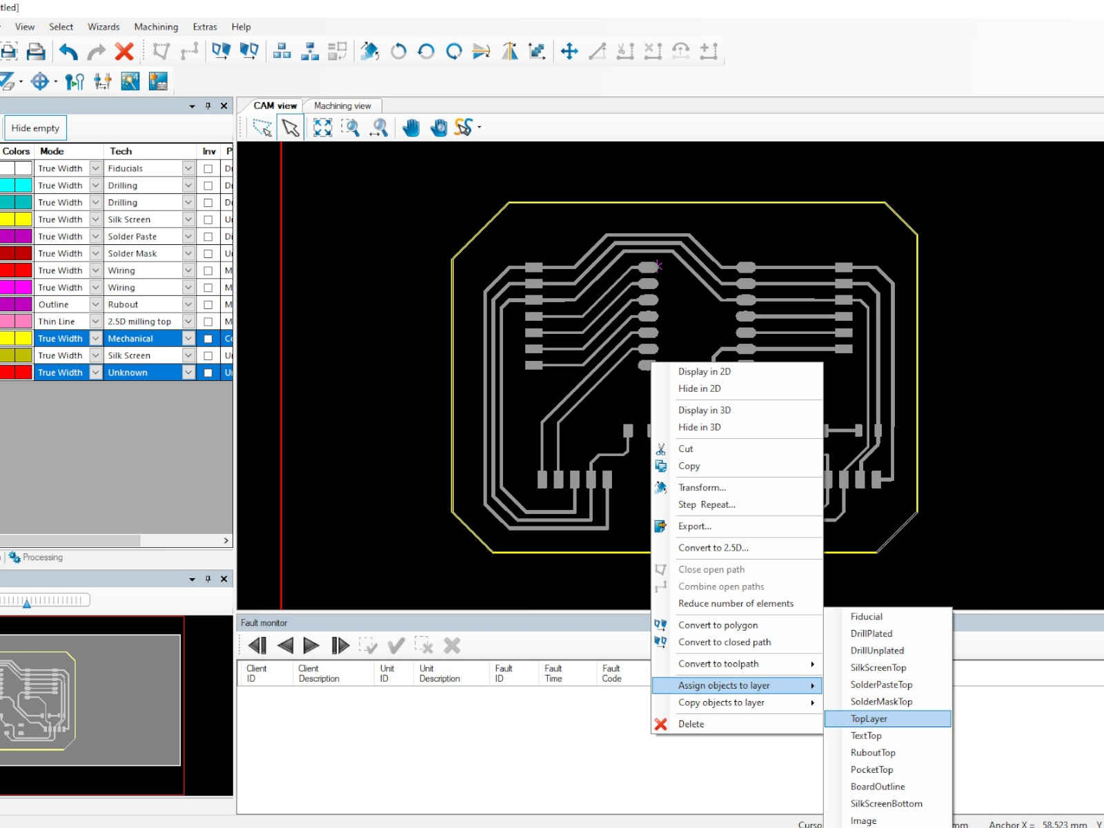 For the holes to be drilled, they were assigned to the layer DrillPlated, when I should had assigned them to DrillUnplated. Also, the circuit design did not present the holes as full circle, which interfered with
the software's ability to determine the appropriate drill bit to be used. I should had edited the circuit design a bit to have the holes presented as full circle.
For the holes to be drilled, they were assigned to the layer DrillPlated, when I should had assigned them to DrillUnplated. Also, the circuit design did not present the holes as full circle, which interfered with
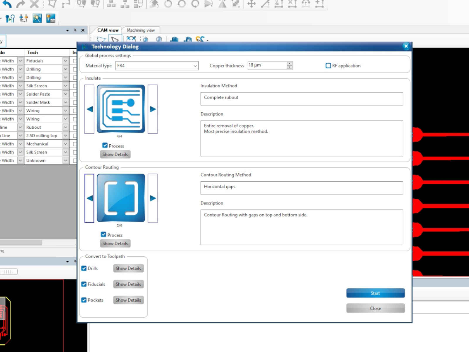
the software's ability to determine the appropriate drill bit to be used. I should had edited the circuit design a bit to have the holes presented as full circle.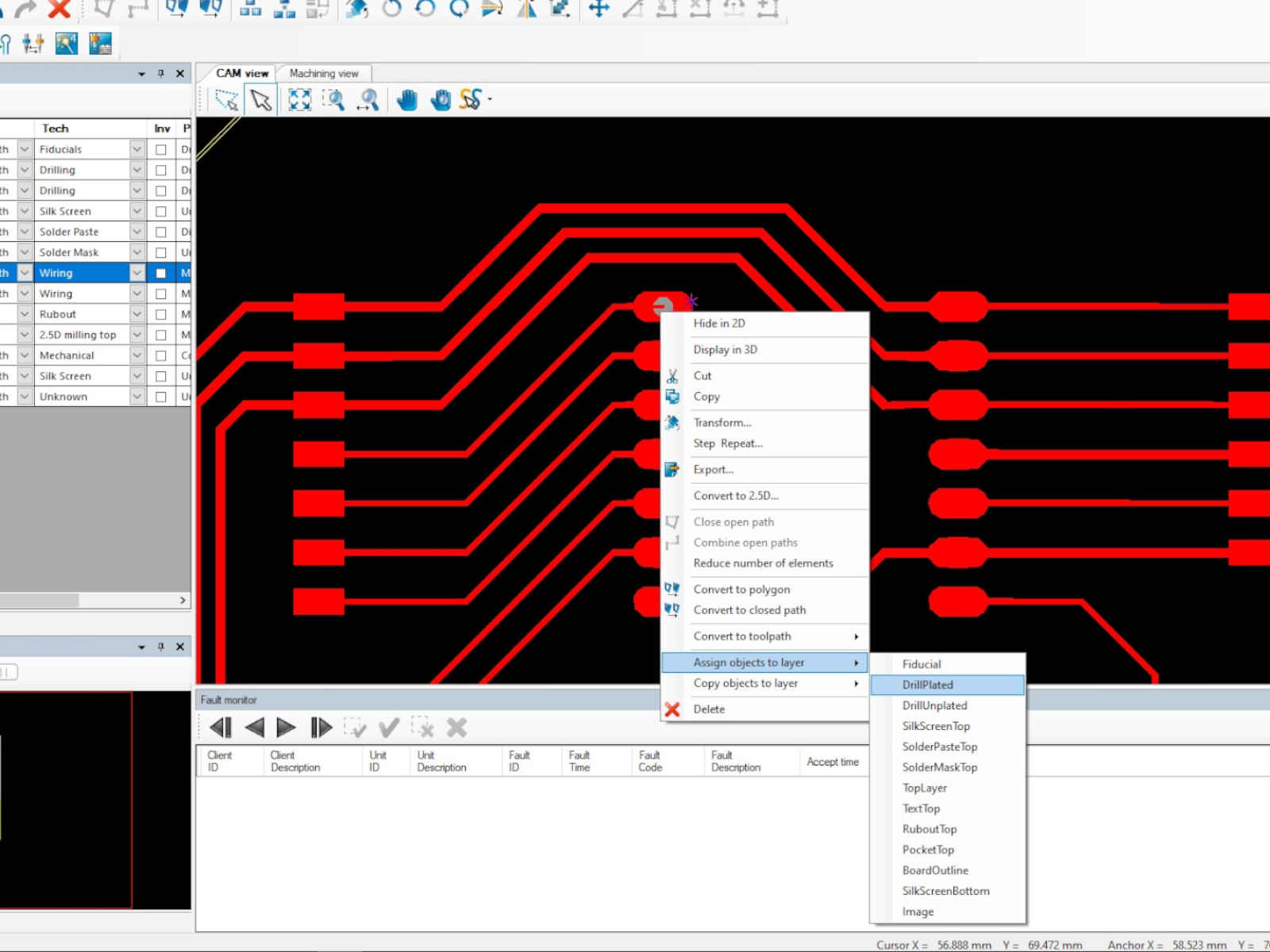 After the layers were assigned, the steps that followed was to generate the toolpath. For that, I went to select Toolpath>Technology Dialog... at the top. The Technology Dialog windows then popped up and from there I
selected the insulate and contour routing options I wanted.
After the layers were assigned, the steps that followed was to generate the toolpath. For that, I went to select Toolpath>Technology Dialog... at the top. The Technology Dialog windows then popped up and from there I
selected the insulate and contour routing options I wanted.
 The software will then compute the toolpath and resquired tool. Here the mistake I made regarding the drill holes surfaced, as the software was unable to determine the drill bit required and I had to select it by myself.
 After I selected the drill bit for the holes, I saved the toolpath.
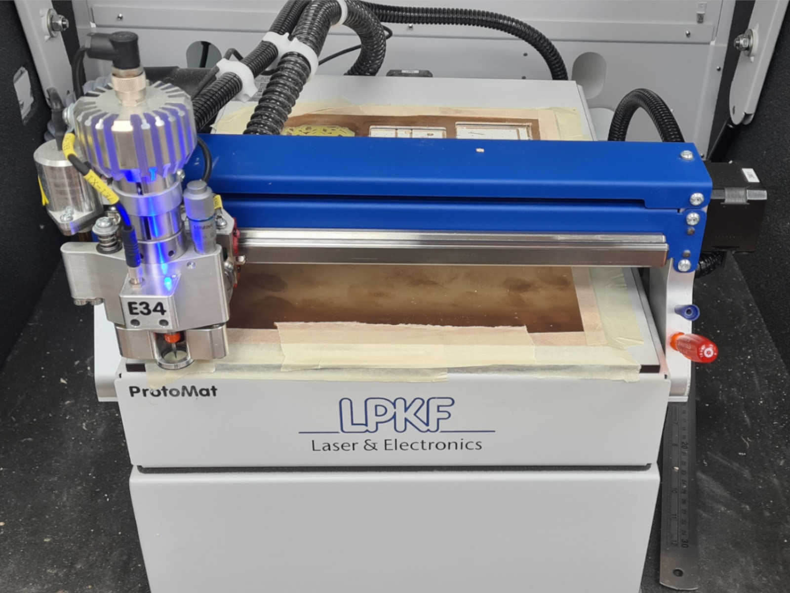
 I am using a used FR4 board, so I carefully selected the placement of the circuit board for the milling
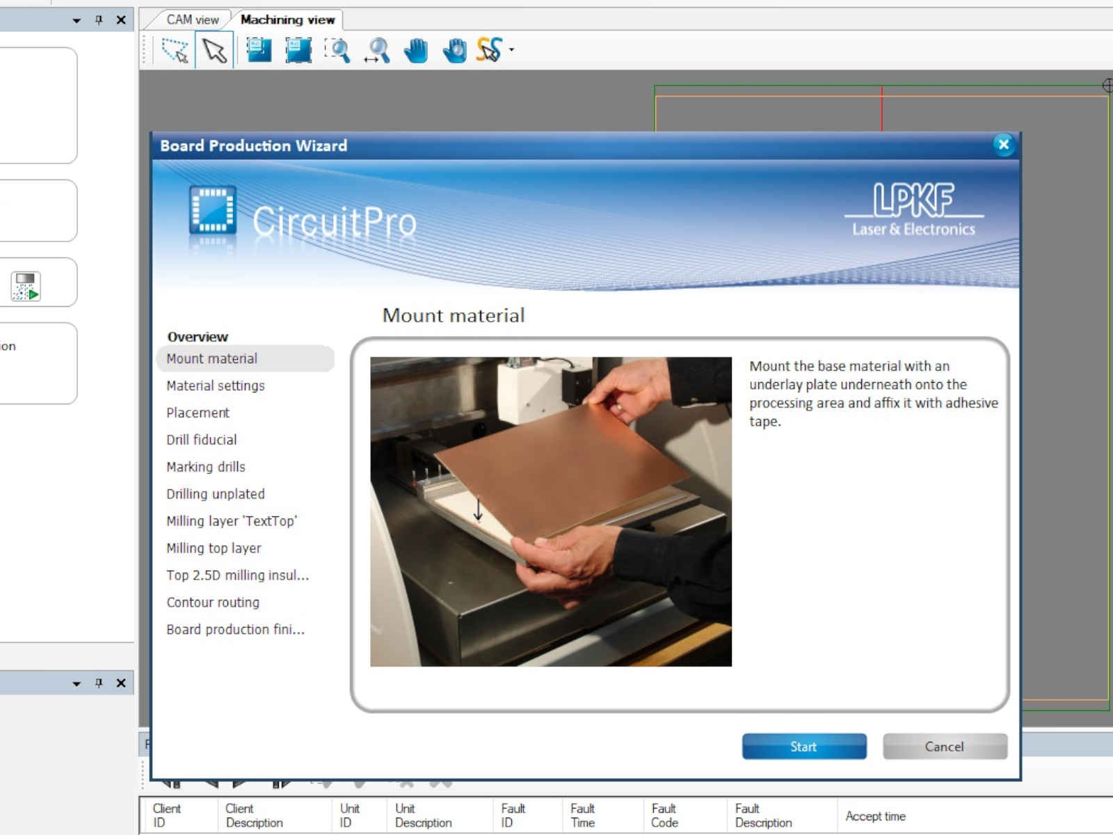
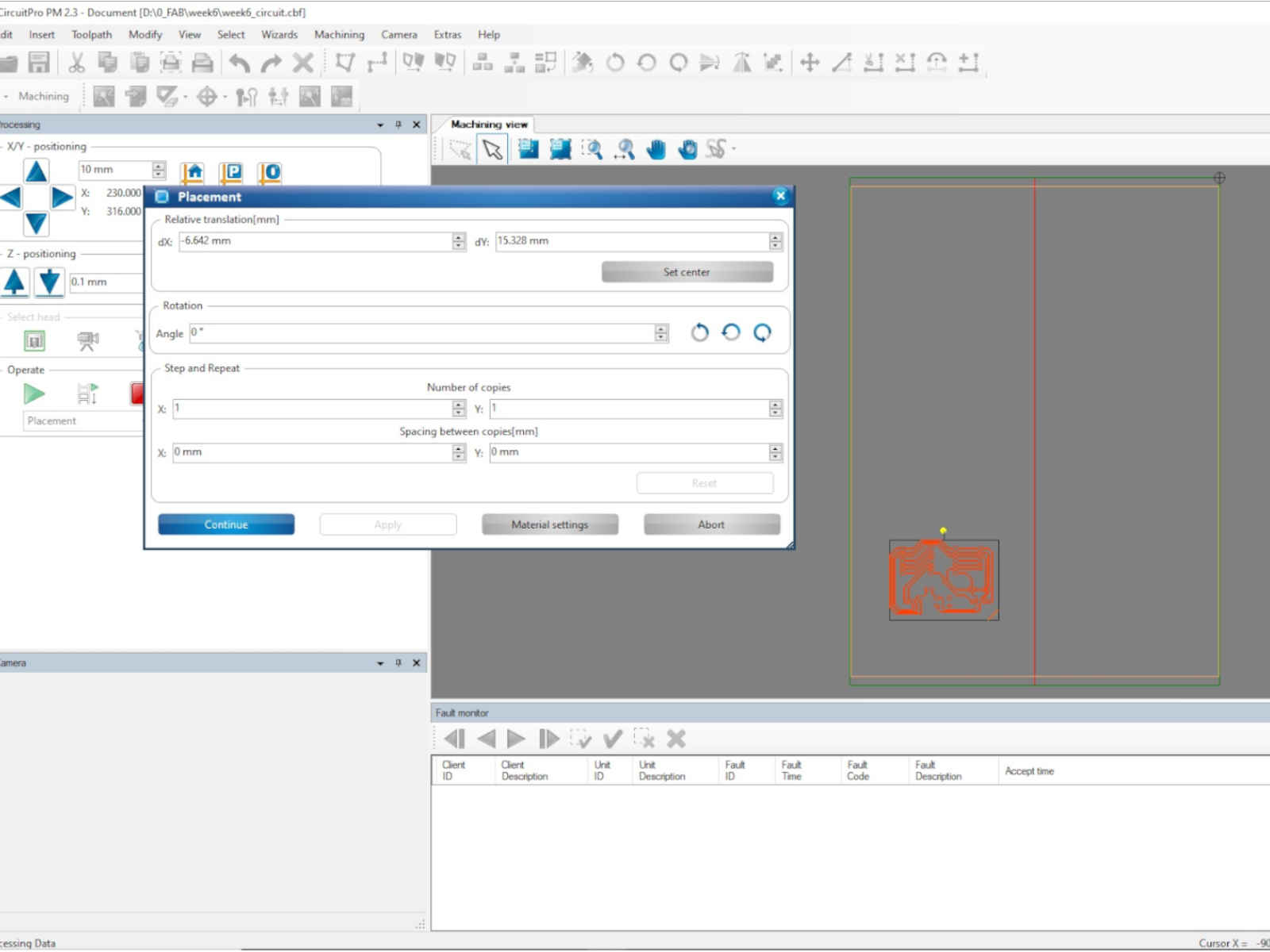 The machine did not have an auto-sampler, so I have to manually change the milling tool according to the instructions.
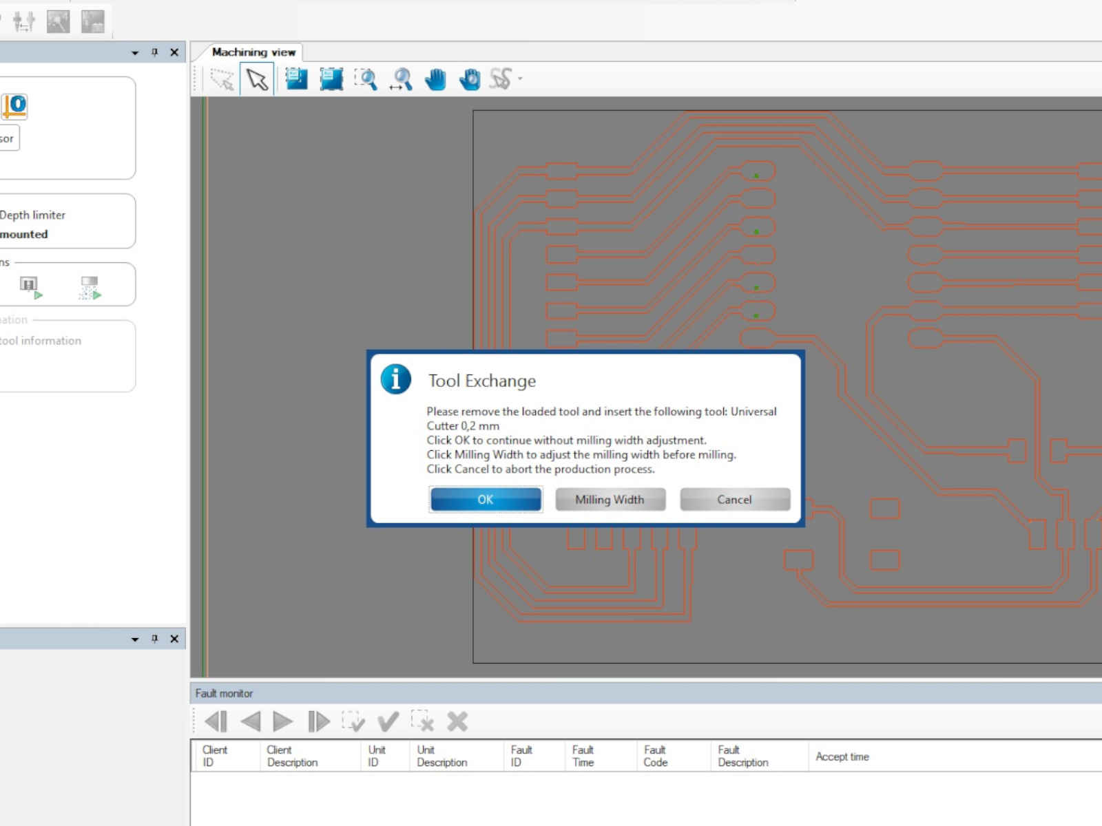 Except for not being able to drill the through holes, the milling went smoothly.
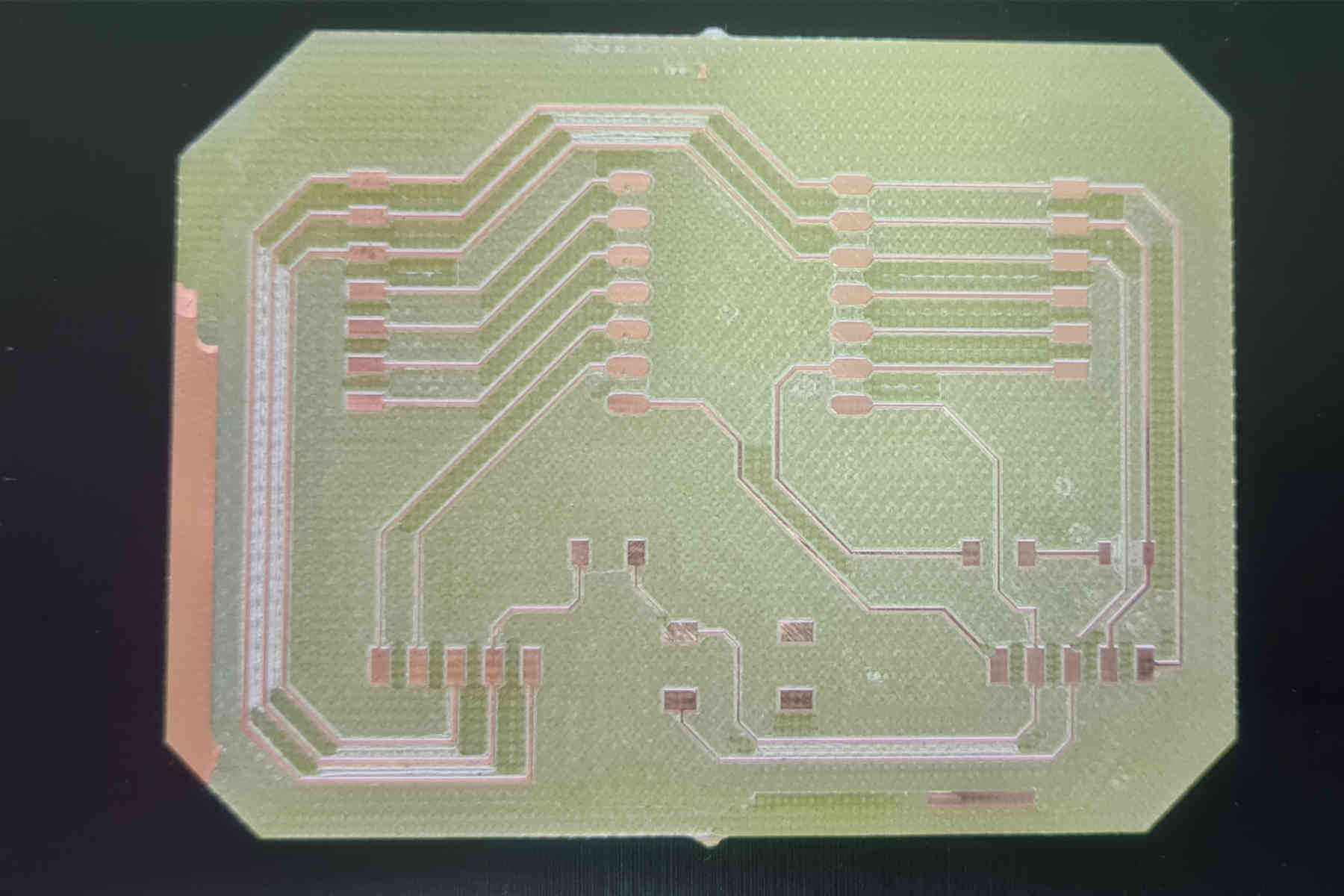
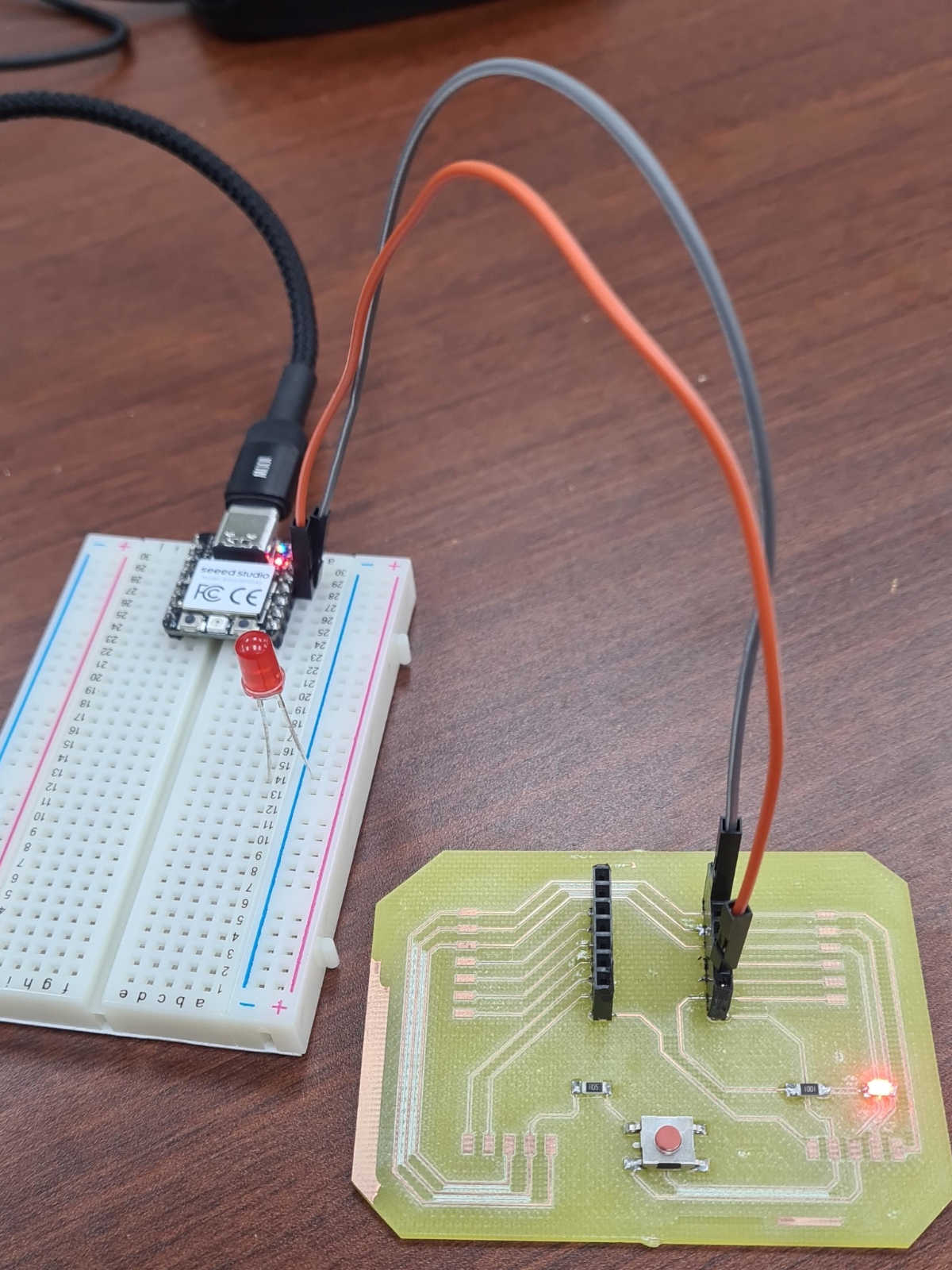 I then inserted the Xiao board back to the circuit board. This time it works.