Week 9: Output Devices
Assignments
The assigments for this week are:Group Assignment
Measure the power consumption of an output device
Individual Assignment
Add an output device to a microcontroller board you've designed, and program it to do something
Group Assignment
For the group assignment, we measured the power consumption of the micro servo motors. What I learned from this group assignment are that the power consumption fluctuate according to the movement of the motors. Having this information on power consumption will be useful when we design our final project. Full documentation can be found on the group assignment page.Individual Assignment
This week's individual assignment is to add an output deviced to the microcontroller board I had designed and program it to do something. In my case, I decided to use a robotic hand I have in the workshop as the output device. This robotic hand is actually a toy robotic hand kit that I attached 5 micro servo motors to for a previous projects.The sketch I used is the servo sweep sketch from the Arduino servo sweep sketch from the Arduino documentation site. In the sketch, I changed the servo pin to D9 of my board.
#include <Servo.h>

Servo myservo;  // create servo object to control a servo
// twelve servo objects can be created on most boards

int pos = 0;    // variable to store the servo position

void setup() {
  myservo.attach(D9);  // attaches the servo on pin D9 to the servo object
}
void loop() {
  for (pos = 0; pos <= 180; pos += 1) { // goes from 0 degrees to 180 degrees
    // in steps of 1 degree
    myservo.write(pos);              // tell servo to go to position in variable 'pos'
    delay(15);                       // waits 15ms for the servo to reach the position
  }
  for (pos = 180; pos >= 0; pos -= 1) { // goes from 180 degrees to 0 degrees
    myservo.write(pos);              // tell servo to go to position in variable 'pos'
    delay(15);                       // waits 15ms for the servo to reach the position
  }
}
The servo library (Servo.h) was included in the sketch. This will indicate that the built-in servo commands will be used in this sketch.
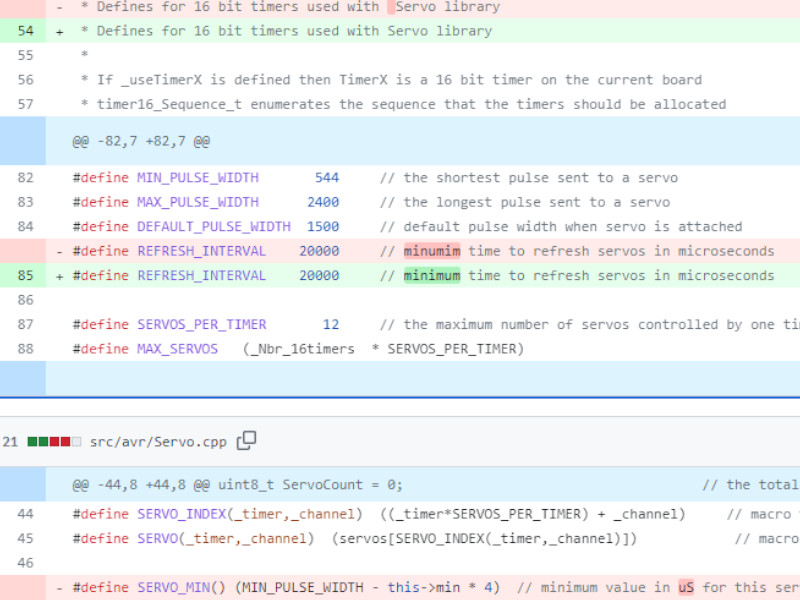
The sketch used PWM signal to control the servo motor. According to the
documentation, the minimum pulse width is 544 microseconds, while the maximum pulse width is 2400 microseconds, with the default pulse width at 1500 microseconds. This means that, in the sketch, the pulse width from 544 to 2400 microseconds
is "mapped" to 0 to 180°, with 1500 microseconds correspond to 90°.
 While testing the servo motors one by one, I found one of the servo motors is not working anymore, so I decided to just control the rest of the 4 servo motors using only pin D9 of my board.
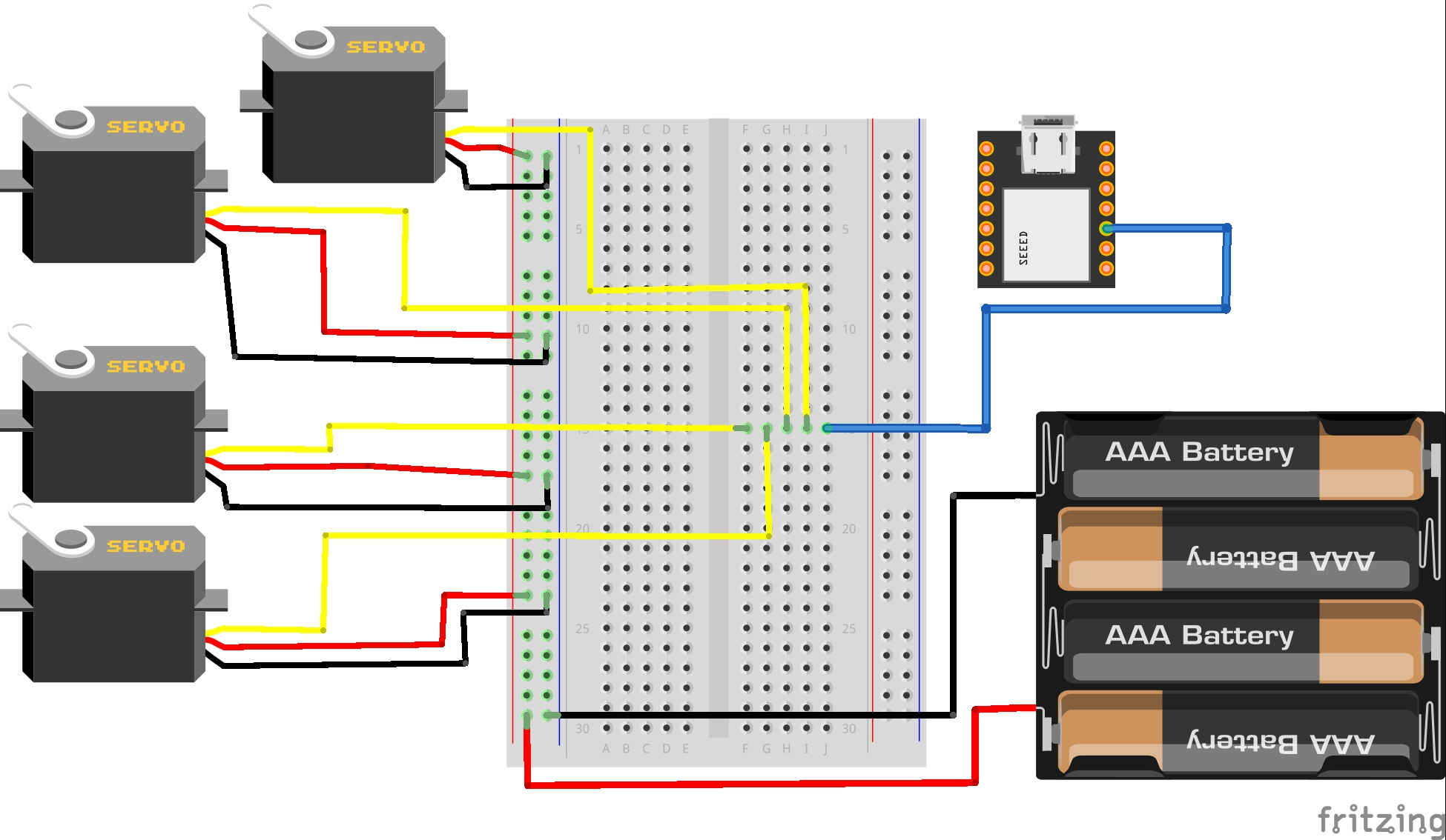 Initially, I wanted to power the servo motors with 4 x AA batteries. However, this didn't seem to work. The servo motors didn't move. Therefore, as a quick solution, I instead supply power the servo motors from the board instead,
using the 5V pin and GND pin.
Initially, I wanted to power the servo motors with 4 x AA batteries. However, this didn't seem to work. The servo motors didn't move. Therefore, as a quick solution, I instead supply power the servo motors from the board instead,
using the 5V pin and GND pin.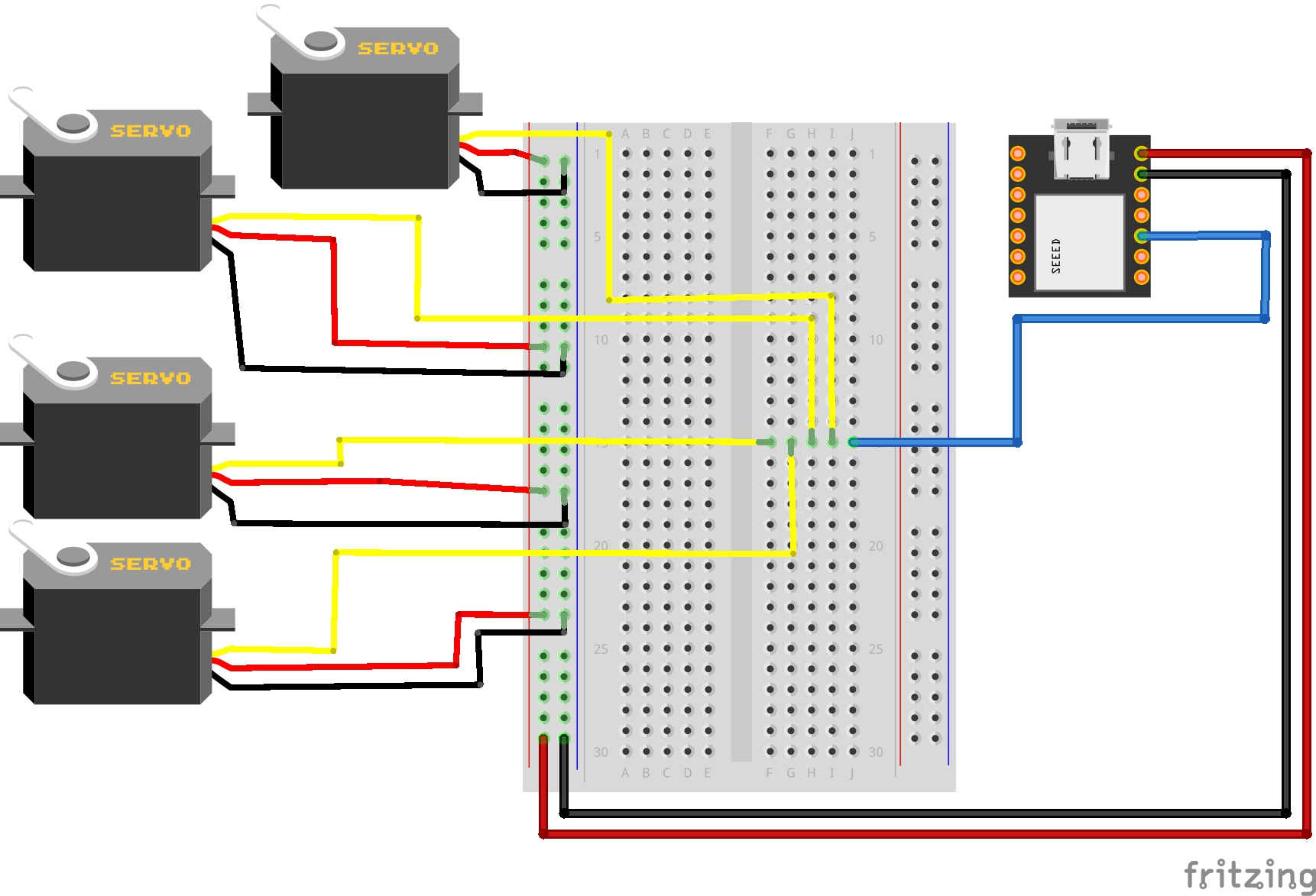 I am aware that this is not the best practice to power the 4 servo motors and was not expecting it to work. I added the servo motor to the circuit one by one to see how many servo motor can I power using the board.
I was a bit suprised that I can power all 4 servo motors from the board.
I am aware that this is not the best practice to power the 4 servo motors and was not expecting it to work. I added the servo motor to the circuit one by one to see how many servo motor can I power using the board.
I was a bit suprised that I can power all 4 servo motors from the board.