Week 11: Input Devices
Lecture Review
This page will be updated after the lecture on Apr 05.Assignments
The assigments for this week are:Group Assignment
Probe an input device's analog levels and digital signals
Individual Assignment
Measure something: add a sensor to a microcontroller board that you have designed and read it
Group Assignment.
This week's group assignment we are supposed to probe an input device's analog levels and digital signals. We decided to probe a RCWL-0516 microwave Doppler radar motion sensor for digital signals and a potentiometer's analog levels. For my part, I focused mostly on the code for the circuit and helped to interpret the signal from the oscilloscope. I had previously worked with a few of the input devices but had not measure their signal before. Therefore, this week's assignment help me to have a better understanding of the input devices. Full documentation can be found on the group assignment page.Individual Assignment
The objective for this week's individual assignment was to add a sensor to a my microcontroller board and read the signal. As we had already explored the RCWL-0516 microwave Doppler radar motion sensor and the potentiometer in the group assignment, I decided to use different sensor. I was interested in the step response sensor as it was mentioned by Neil during the lecture that it can measure a lot of things. Though I felt that the sensor might be useful for my final project, I didn't quite understand how the sensor works. Therefore I consulted instructor Steven about it. I learned was that the set up of the sensor was quite straightforward. I just need to connect two metal plates to the microcontroller. The value being measured is the changes in electric field between the metal plates.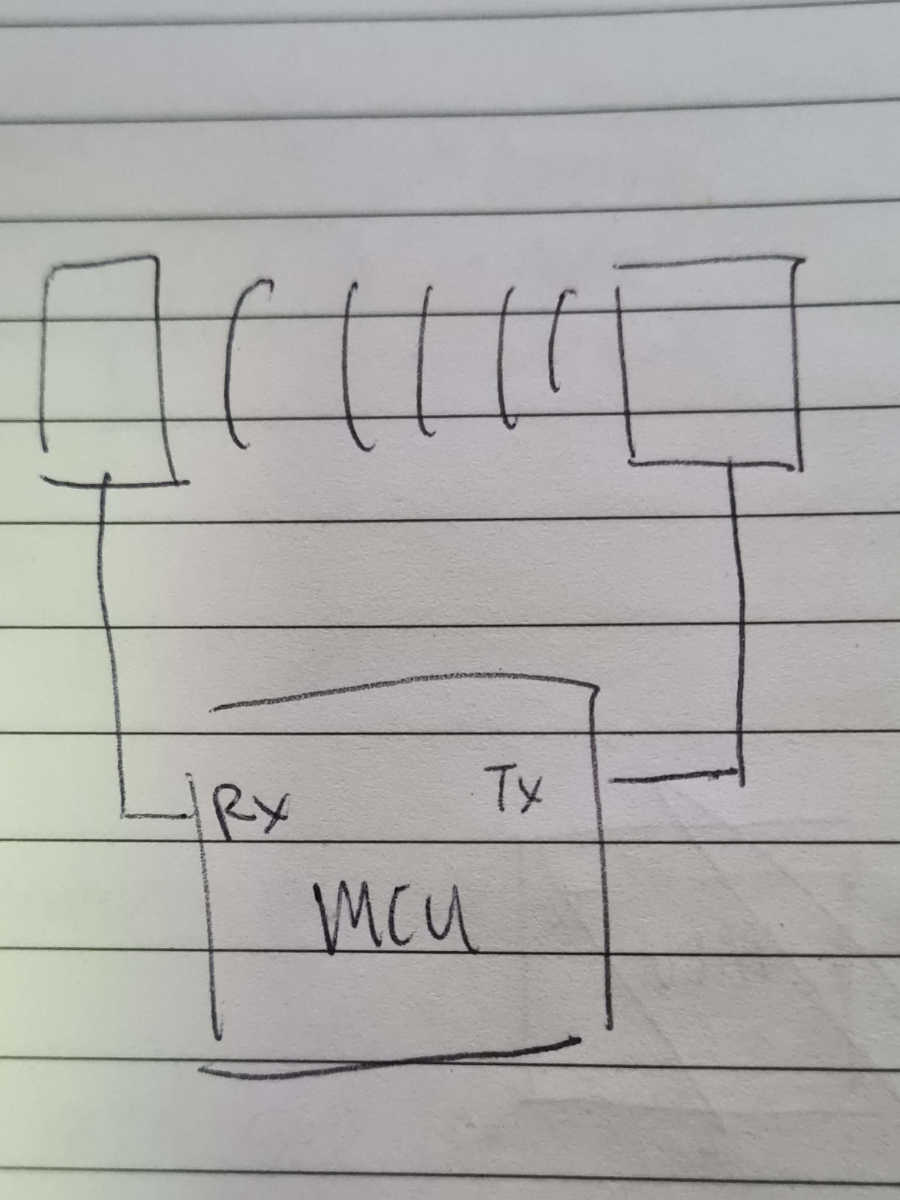 I decided to set up the step response sensor. To begin, I took two copper plate and solder a wire to each of them.
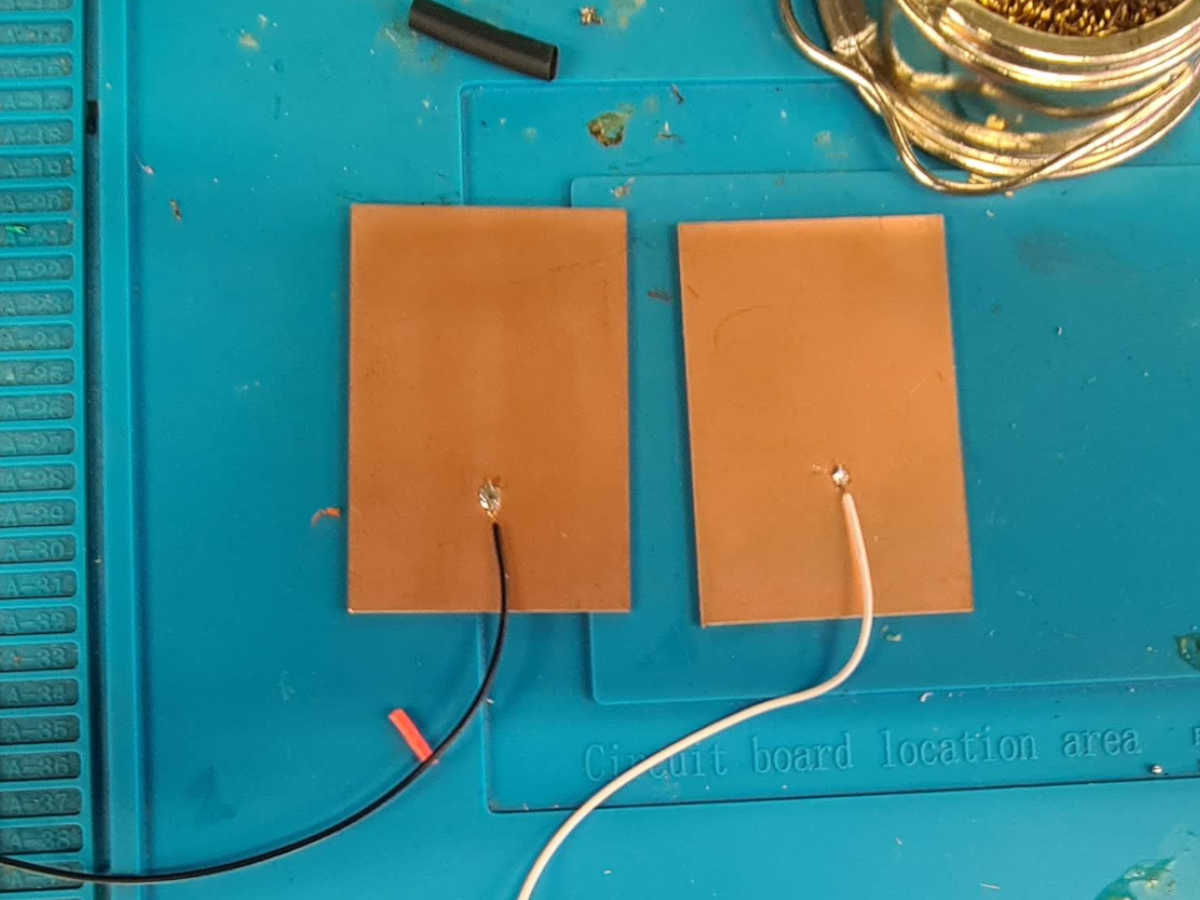 Next, I assembled the circuit. One copper plate was connected to pin D10, which is the Tx pin, while the other pin is connected to pin A0, which is the Rx pin.
 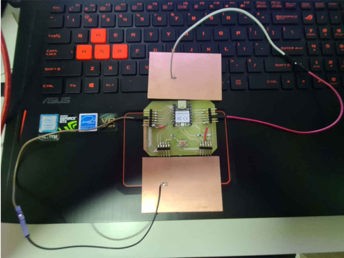 For the code, I took reference from Robert hart's github page. Using his sketch for single measurement,
I changed the Tx/Rx pin for my microcontroller board:
For the code, I took reference from Robert hart's github page. Using his sketch for single measurement,
I changed the Tx/Rx pin for my microcontroller board:
//  Adapted from: rx_tx01  Robert Hart Mar 2019.
//  Program to use transmit-receive across space between two conductors.
//  One conductor attached to pin D10, one to A0
//
//
//  Signal varies with electric field coupling between conductors, and can
//  be used to measure many things related to position, overlap, and intervening material
//  between the two conductors.
//

int read_high;
int read_low;
int diff;

void setup() {
pinMode(D10,OUTPUT);      //Pin D10 provides the voltage step
Serial.begin(9600);
}

void loop() {

   digitalWrite(D10,HIGH);              //Step the voltage high on conductor 1.
   read_high = analogRead(A0);        //Measure response of conductor 2.
   delayMicroseconds(100);            //Delay to reach steady state.
   digitalWrite(D10,LOW);               //Step the voltage to zero on conductor 1.
   read_low = analogRead(A0);         //Measure response of conductor 2.
   diff = read_high - read_low;       //desired answer is the difference between high and low.

Serial.println(diff);
delay(100);

}
After uploading the code, I was able to observe the signal change in the serial monitor when I touch the D10 copper plate and when I placed the two copper plates close to each other.
The step response sensor is certainly a suitable sensor for my final project and next step is to explore the possibility of making another board for this sensor.