Week 12: Molding and Casting
Updates
[12/06/2023]- Added .f3d file of the mold under Design Files
Assignments
The assigments for this week are:Group Assignment
Review the safety data sheets for each of your molding and casting materials, then make and compare test casts with each of them.
Individual Assignment
Design a mold around the stock and tooling that you'll be using, mill it (rough cut + three-axis finish cut), and use it to cast parts.
Group Assignment
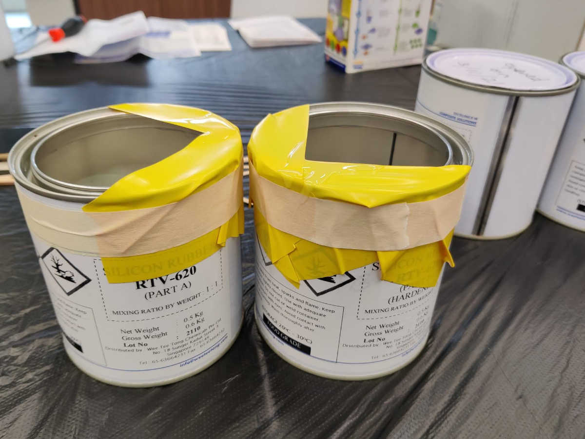
For this week's group assignment, we reviewed the safety data sheets of the molding and casting materials we used. Then we make and compare test casts with each of them. I contributed to the group assignment by trying out the RTV 620 silicon molding masting and the Jesmonite casting material. From this group assignment, I am more aware about the safety aspect of molding and casting. Full documentation can be found on the group assignment page.Individual Assignment
This week's assignment is to deisgn and mill a mold, then use it to cast parts. For the mold design, I took I inspiration from red turtle cake, a popular Chinese pastry, which is made using a mold in the shape of a turtle shell.Designing the mold
I decided to design the turtle shell-like shape using Fusion 360. I started by drawing a regular diamond shape and offset the shape 6 times: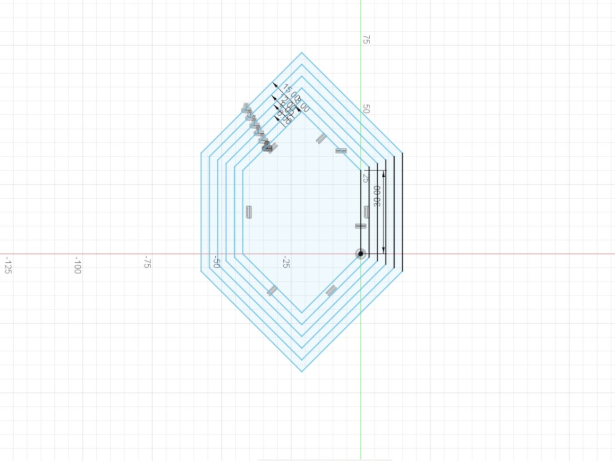 Next, I drew intersecting lines across the offsets, next to all the corners:
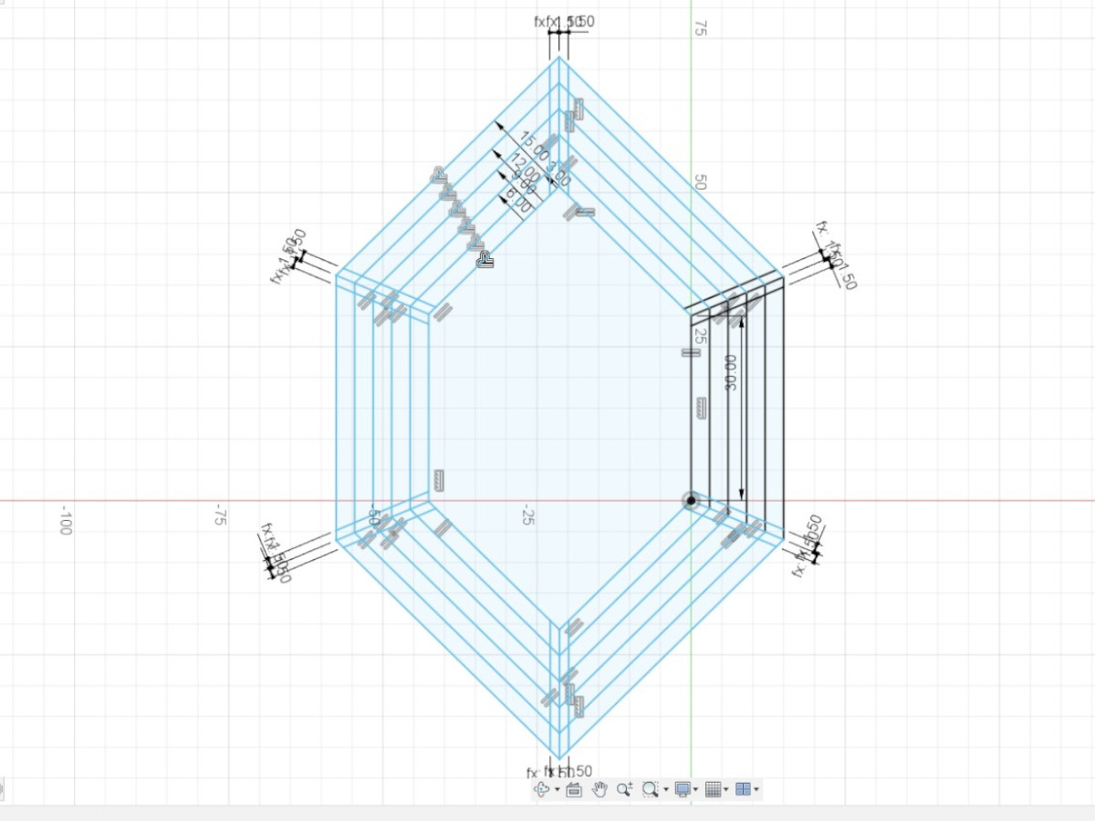 To get the pattern of the shell, I removed the unwanted lines and fileted the resulting corners:
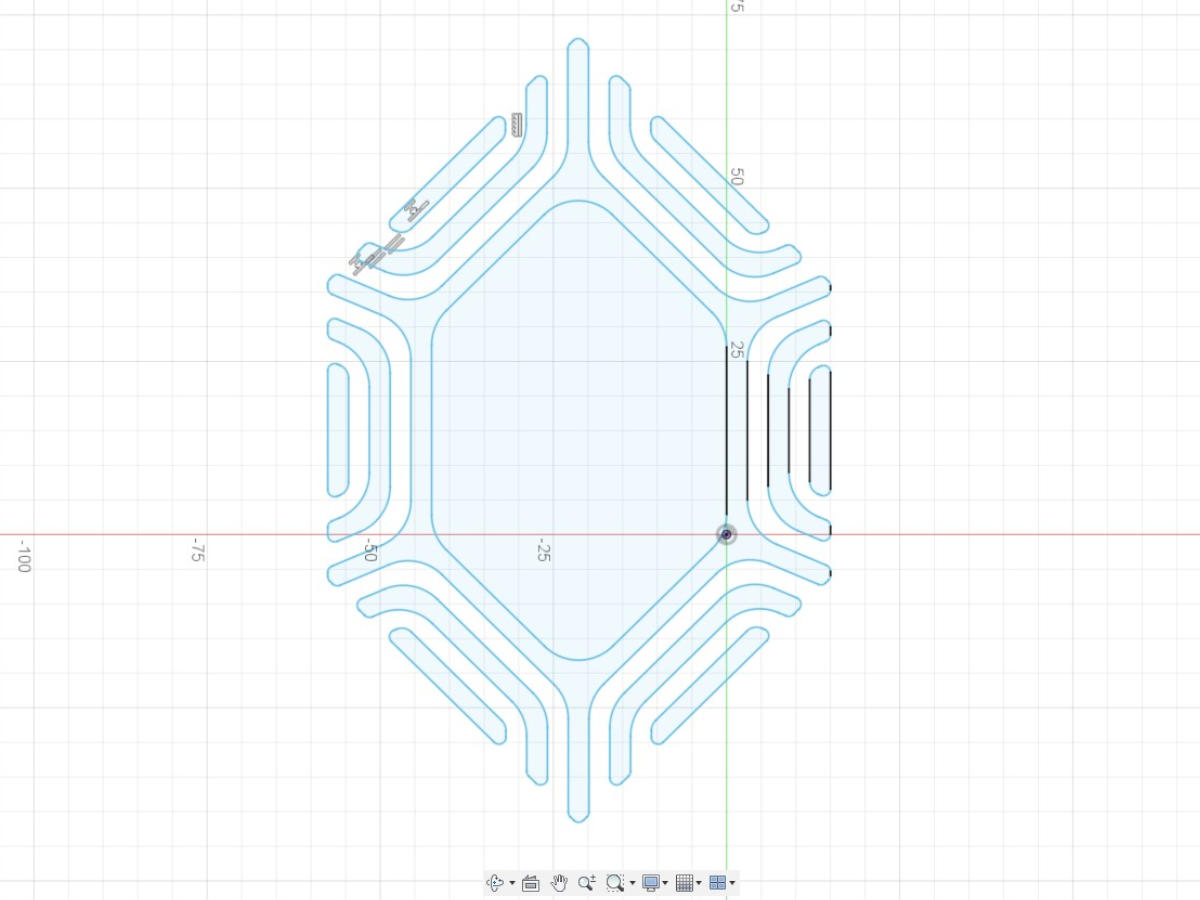 I then proceed to create the shape of the shell. To do that, I first generate an offset plane. On that plane, I drew two ellipses, with the inner ellipse covering the whole shell design.
After that, I revolved the inner ellipse and extruded the outer ellipse.
I then proceed to create the shape of the shell. To do that, I first generate an offset plane. On that plane, I drew two ellipses, with the inner ellipse covering the whole shell design.
After that, I revolved the inner ellipse and extruded the outer ellipse.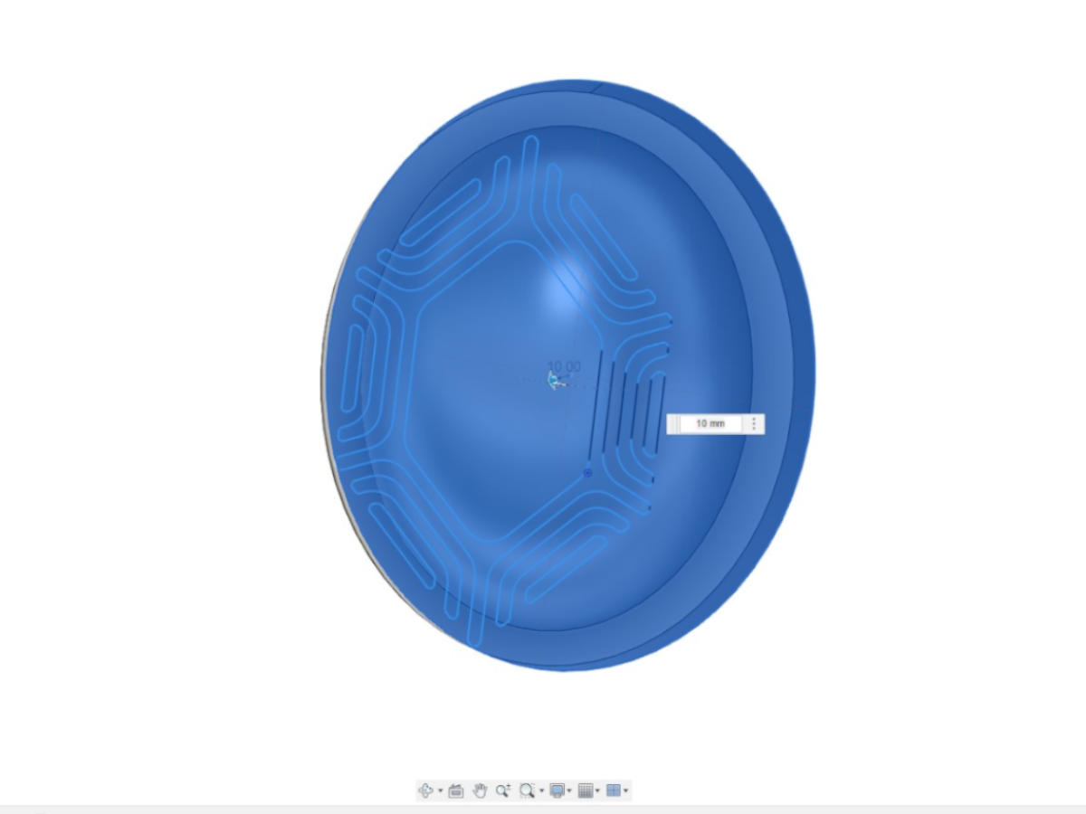 The next step is to imprint the shell pattern onto the shell. To do that, I first made two more copies of the shell.
Then, I extruded the pattern onto the shell to cut away the intersecting parts.
The next step is to imprint the shell pattern onto the shell. To do that, I first made two more copies of the shell.
Then, I extruded the pattern onto the shell to cut away the intersecting parts.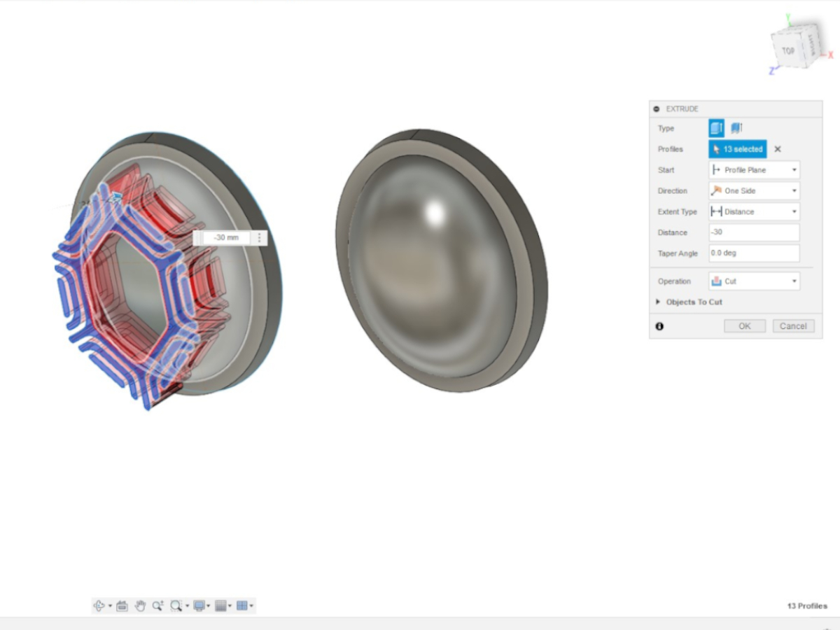 This cut shell was then in turn used to cut a copy of the original shell using the combine function (the cavity was the tool, original shell was the target). This gives the extruded pattern.
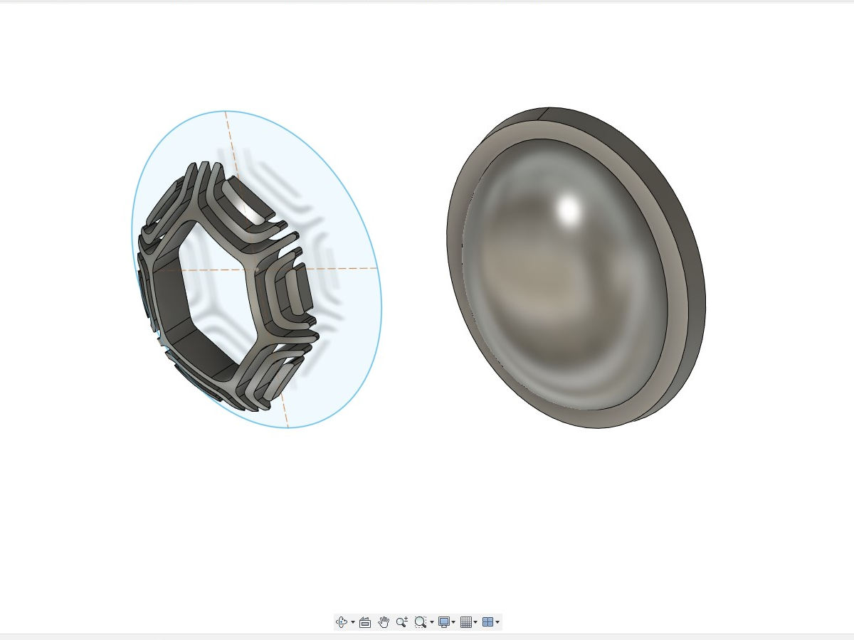 The extruded pattern was then aligned with another copy of the original shell and lifted by 3mm. The extruded pattern was combined (join) with the shell and filleted to complete the model.
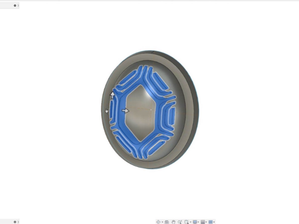 A Chinese character for luck was added to the centre afterward, using the method described above. The model was then exported as STL file.
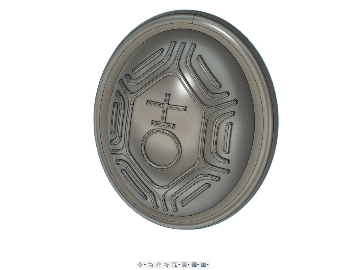
Milling the Model
The model was milled using Roland DGA Modela MDX-50 CNC milling machine. I first placed the material (resin wood) onto the milling table. The material was secured with double side tape. Then, the user coordinates of the machine was set with the top-center of the material as the original.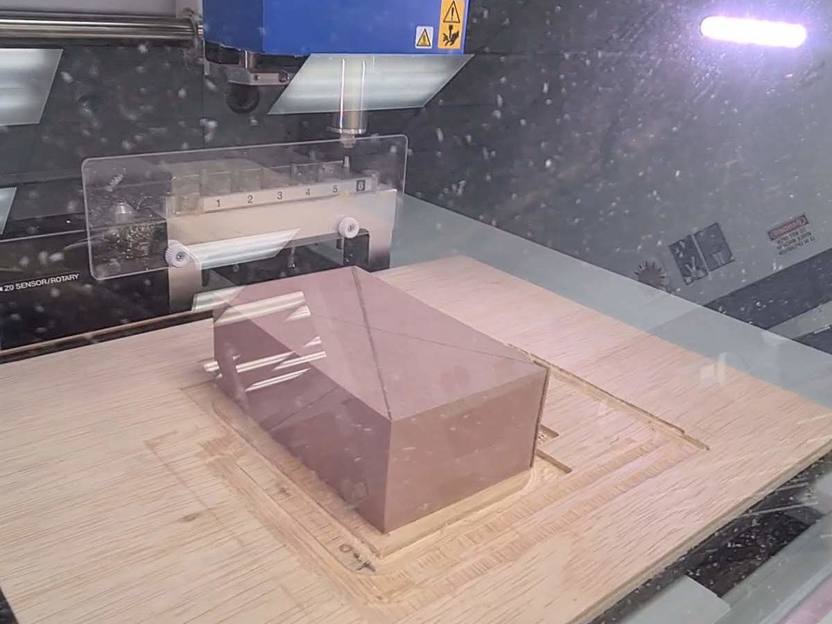 Next, the STL file of the model was opened in SRP player to process for milling. The SRP player provide step-by-step instruction to prepare the model.
The first step is to determine the size of the model. Instructor Steven cautioned me that the overhangs in the model might not mill well, I therefore "flatten" the model by reducing the height of the model by almost half.
Next, the STL file of the model was opened in SRP player to process for milling. The SRP player provide step-by-step instruction to prepare the model.
The first step is to determine the size of the model. Instructor Steven cautioned me that the overhangs in the model might not mill well, I therefore "flatten" the model by reducing the height of the model by almost half.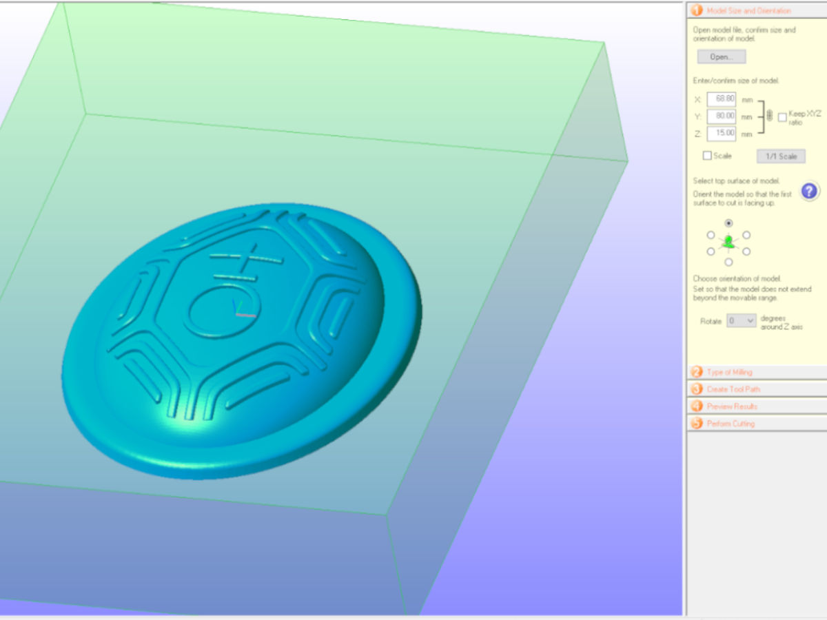 The next step was choosing the type of milling and I chosen to have better finish.
 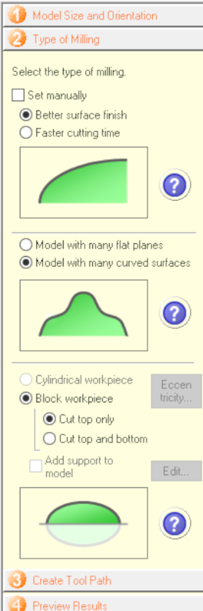 Following that, the third step was to create tool path.
The software suggested roughing with the R3 ball mill and finishing with a R1.5 ball mill.
I found that the suggested toolpath will take quite long (4.5 hours), therefore, I decided to add one more roughing step at the beginning with a 6mm end mill to remove top portion first.
I also adjusted the roughing with R3 and finishing to start before the surface of the workpiece. These edits reduced the milling time by 1.4 hour to 3.1 hours of cutting time.
Following that, the third step was to create tool path.
The software suggested roughing with the R3 ball mill and finishing with a R1.5 ball mill.
I found that the suggested toolpath will take quite long (4.5 hours), therefore, I decided to add one more roughing step at the beginning with a 6mm end mill to remove top portion first.
I also adjusted the roughing with R3 and finishing to start before the surface of the workpiece. These edits reduced the milling time by 1.4 hour to 3.1 hours of cutting time.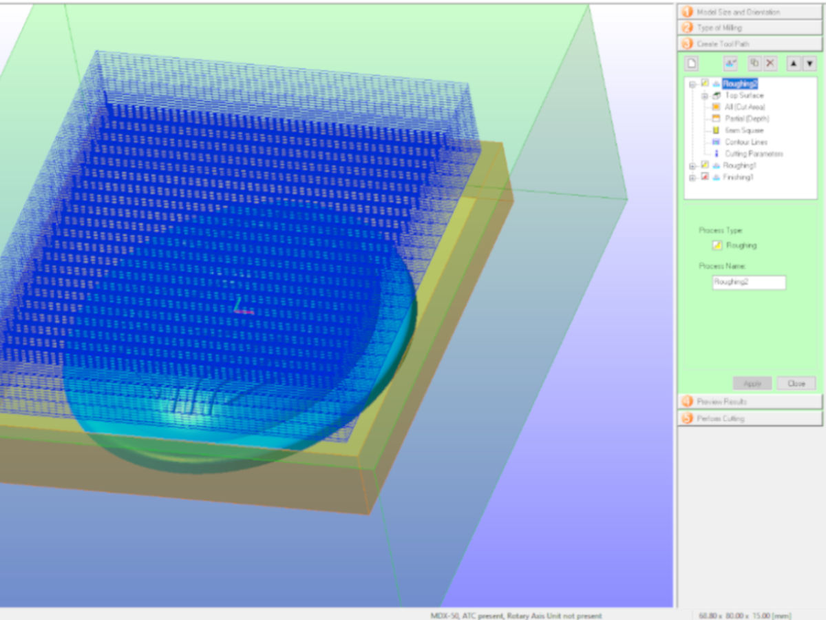 The next step is to review the cutting, where I was able to see a simulated model of the model and the estimated milled time
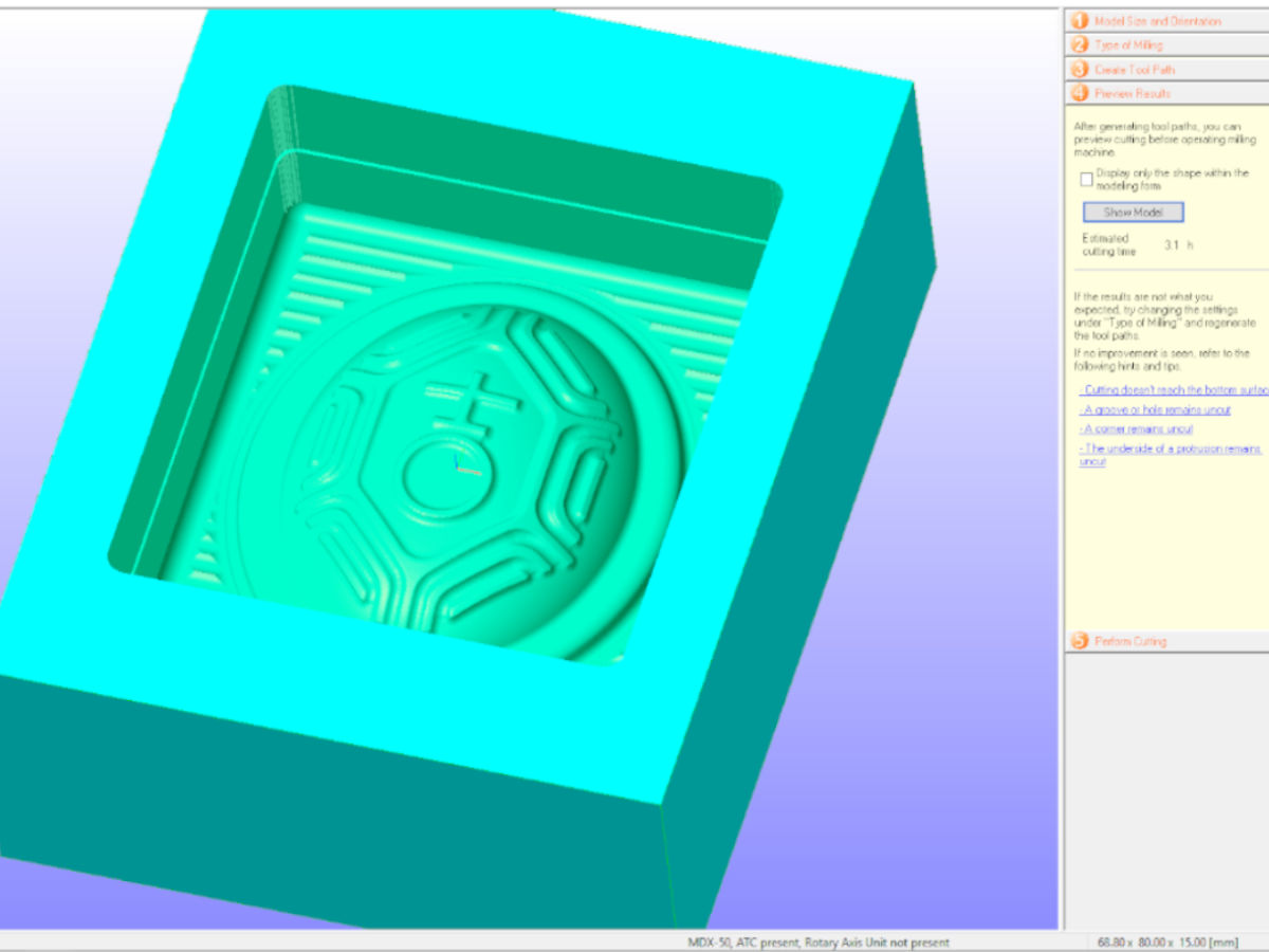 Finally, the last step is to submit for milling. In this step, it is important to indicate the origin correctly. In my case, the origin is at the top centre.
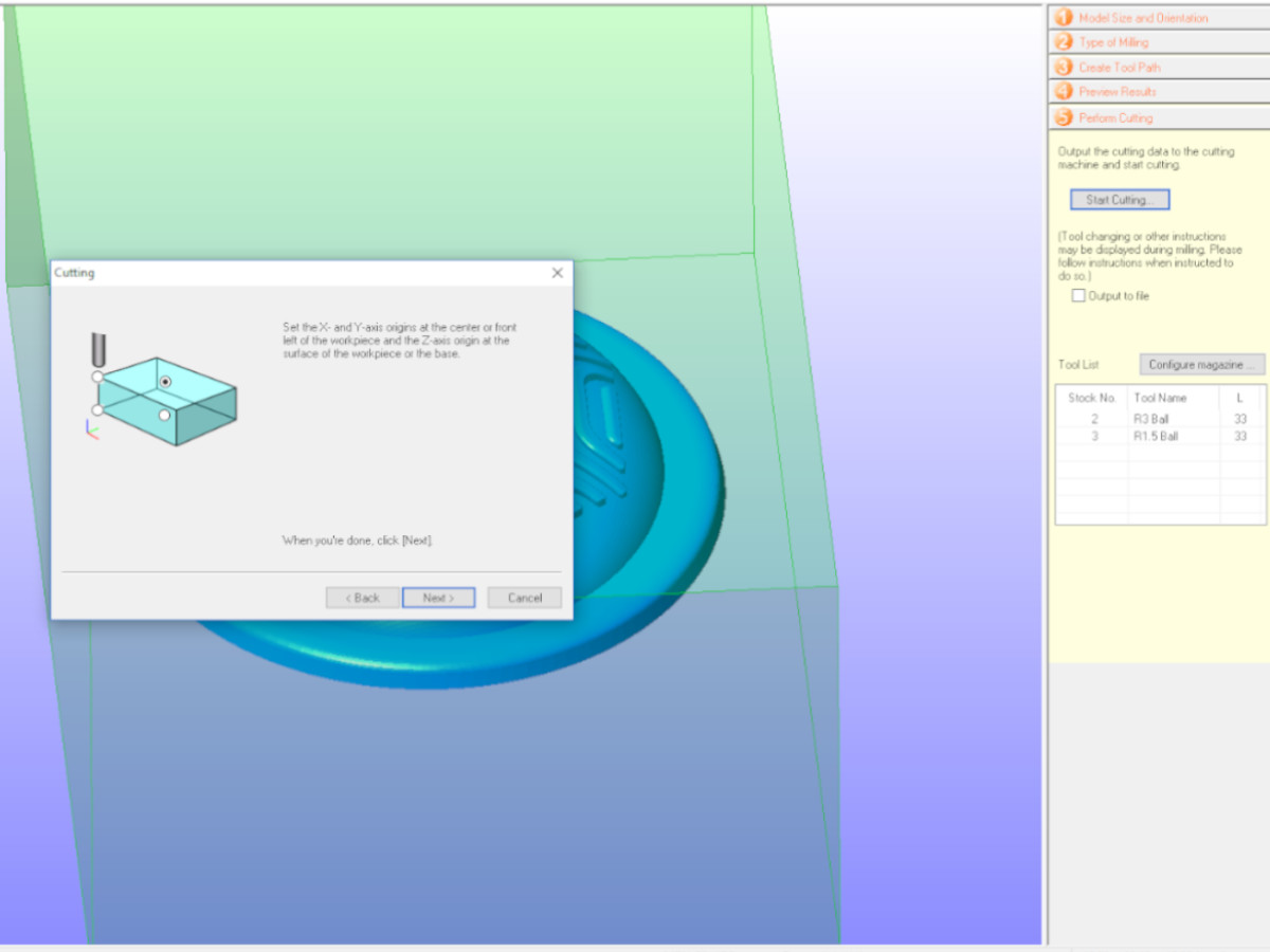 The milling began immediately after the job was submitted to the machine. After about an hour roughing, the model started to take shape.
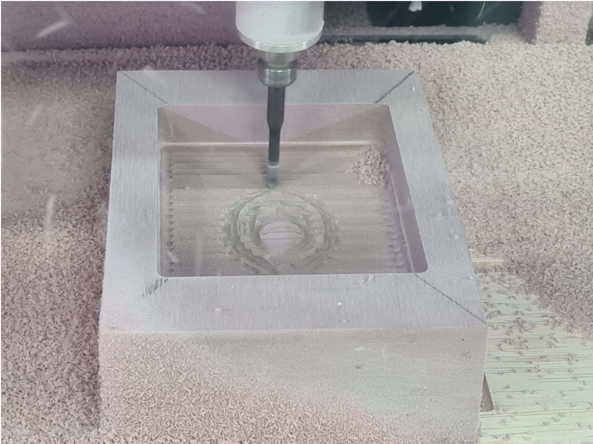 During the smoothing process, I can see that the details are all milling well.
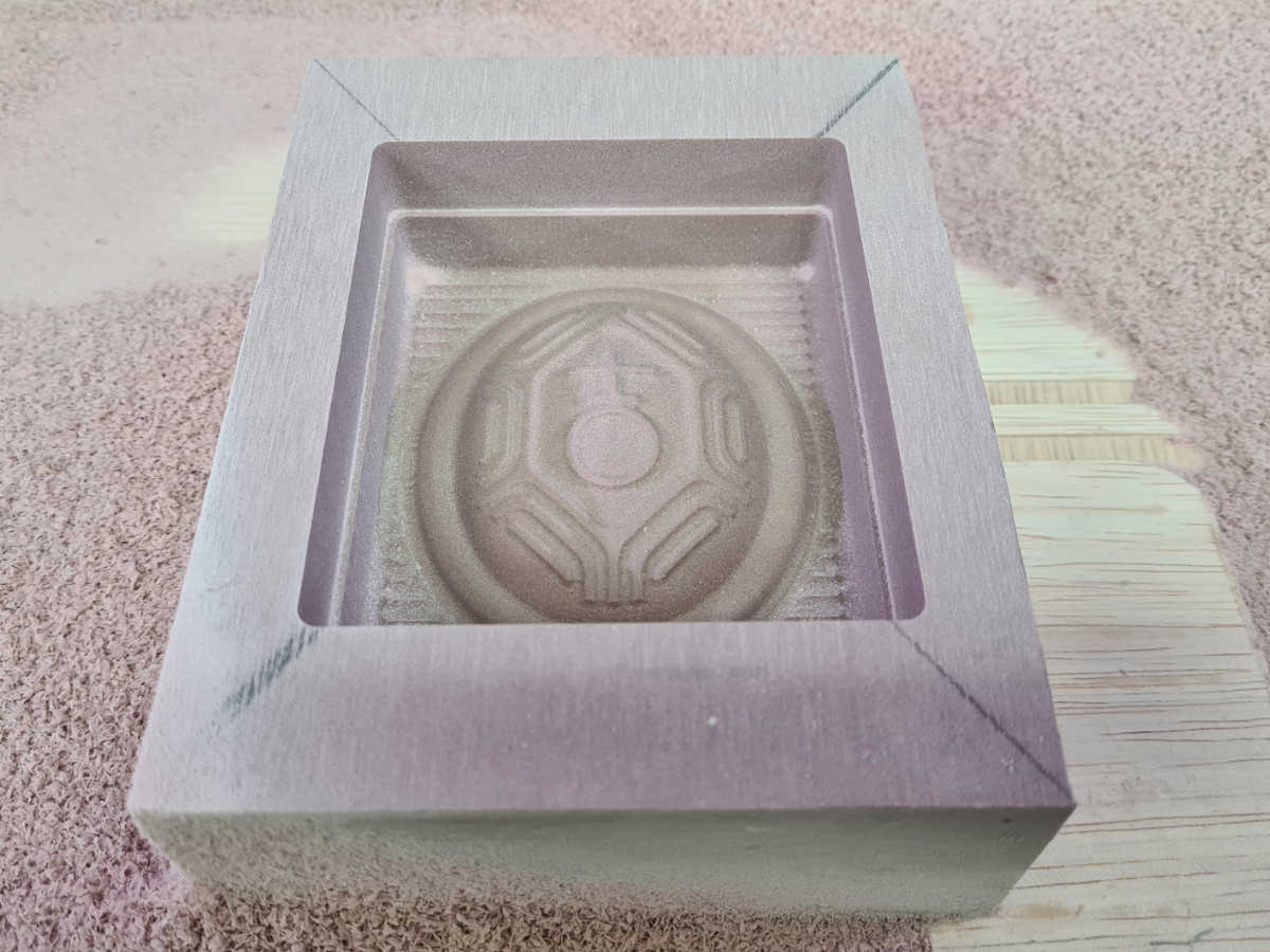
After 3.1 hours the model is completed and ready for molding.
Molding
To make the mold, we used rubber silicon.
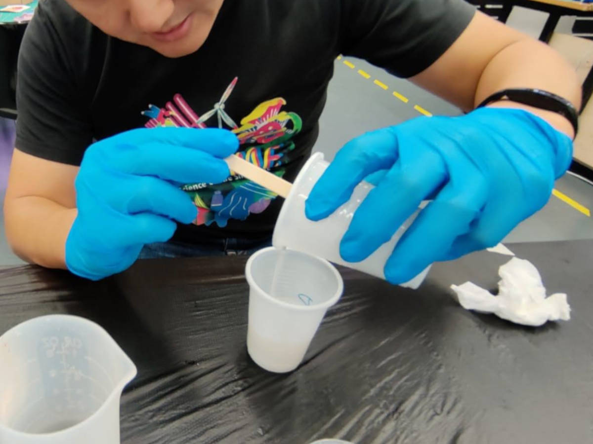 I slowly and evenly stirred the viscous mixture to avoid bubbles forming. I stirred for about 8 mins, until the mixture is mixed evenly.
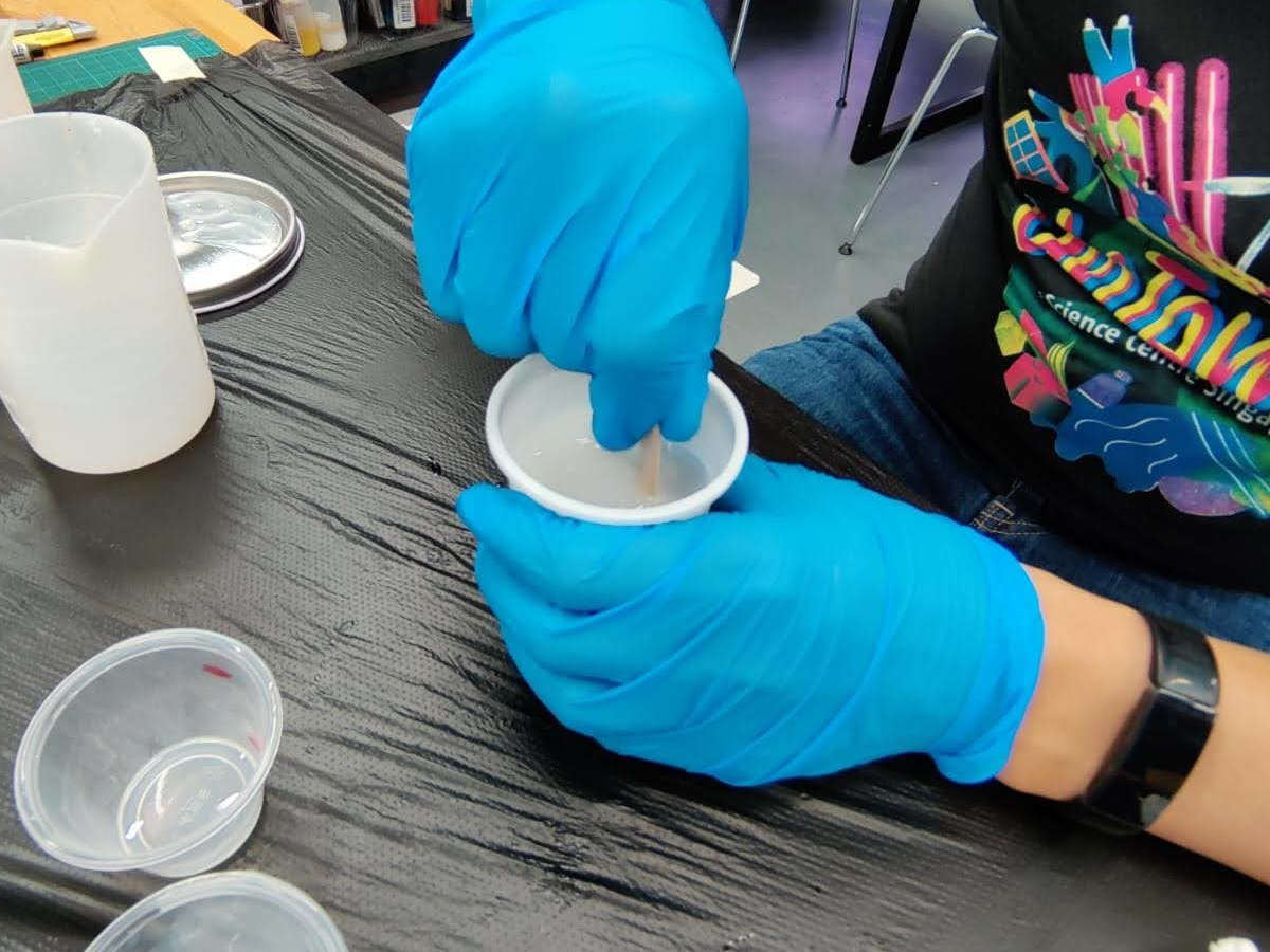 The mixture was then poured slowly and carefully onto the model and left to stand.
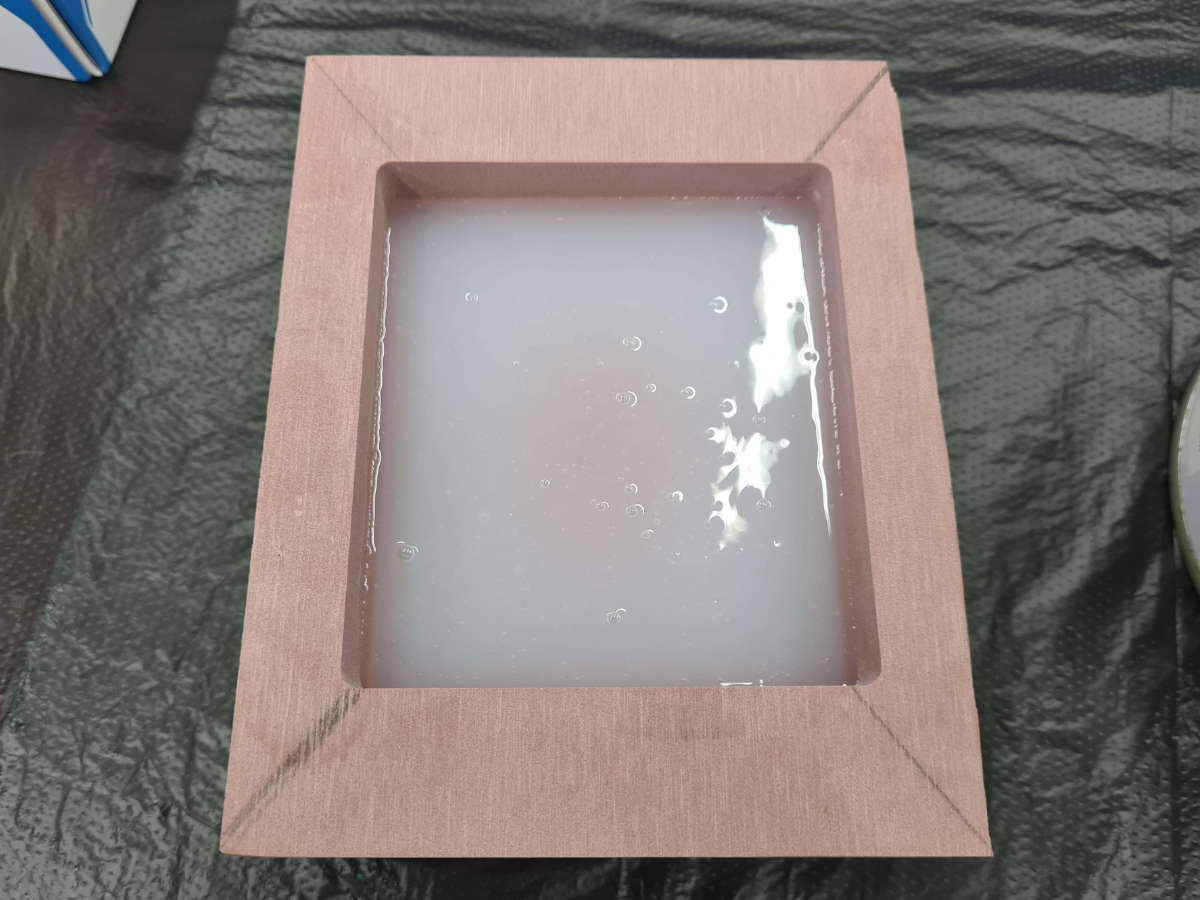 The slicon mixture was supposed to set after 24 hours, but after 48 hours, the mixture was still semi-solid with uneven hardening. Instructor Steven said that this could be that the A/B portion was not 1:1 and not evenly mixed.
So I re-did the mold. I did as suggested and this time I ensured the A/B mixture was 1:1 and mixed evenly.
Although the mixture did set more evenly this time, similar to the previous attempt it was not fully set after 24 hours. I then put semi-solid mold in a filament dry box and applied some heat.
After about 2 hours, the surface of the mold was set, but when I tried to lift it up at the corner, it was still not set underneath. As I observed that the pervious spolit mold actually set after letting it stand further,
I figured the mold might just be slow in setting, so I left it to set over the 3-day long weekend.
After standing for 3 days, the mold was indeed fully set and I was able to remove it successfully. There was a dent at one corner, which I think was caused by the air bubble that
was created when I lifted the mold up at that corner previously.
The slicon mixture was supposed to set after 24 hours, but after 48 hours, the mixture was still semi-solid with uneven hardening. Instructor Steven said that this could be that the A/B portion was not 1:1 and not evenly mixed.
So I re-did the mold. I did as suggested and this time I ensured the A/B mixture was 1:1 and mixed evenly.
Although the mixture did set more evenly this time, similar to the previous attempt it was not fully set after 24 hours. I then put semi-solid mold in a filament dry box and applied some heat.
After about 2 hours, the surface of the mold was set, but when I tried to lift it up at the corner, it was still not set underneath. As I observed that the pervious spolit mold actually set after letting it stand further,
I figured the mold might just be slow in setting, so I left it to set over the 3-day long weekend.
After standing for 3 days, the mold was indeed fully set and I was able to remove it successfully. There was a dent at one corner, which I think was caused by the air bubble that
was created when I lifted the mold up at that corner previously.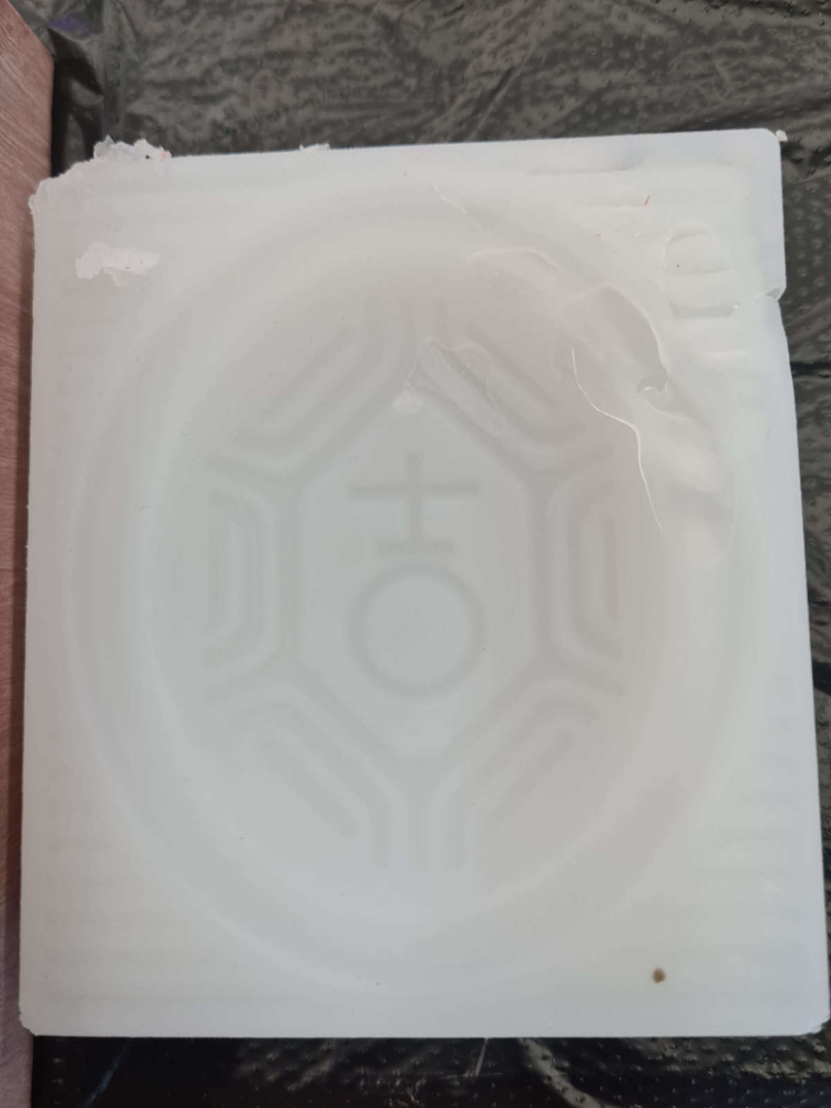
Casting
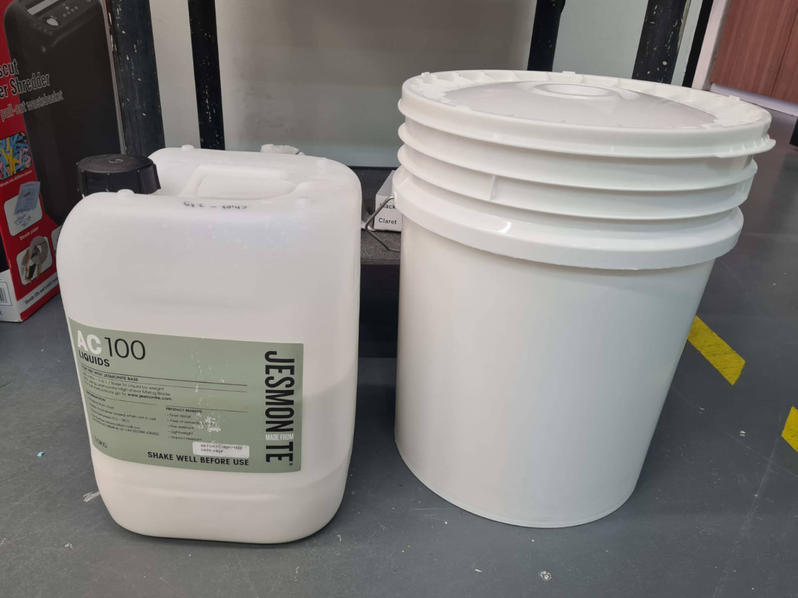
The next step is to cast the mold. For this, I used Jesmonite, which consist of two components - a powder and a liquid.
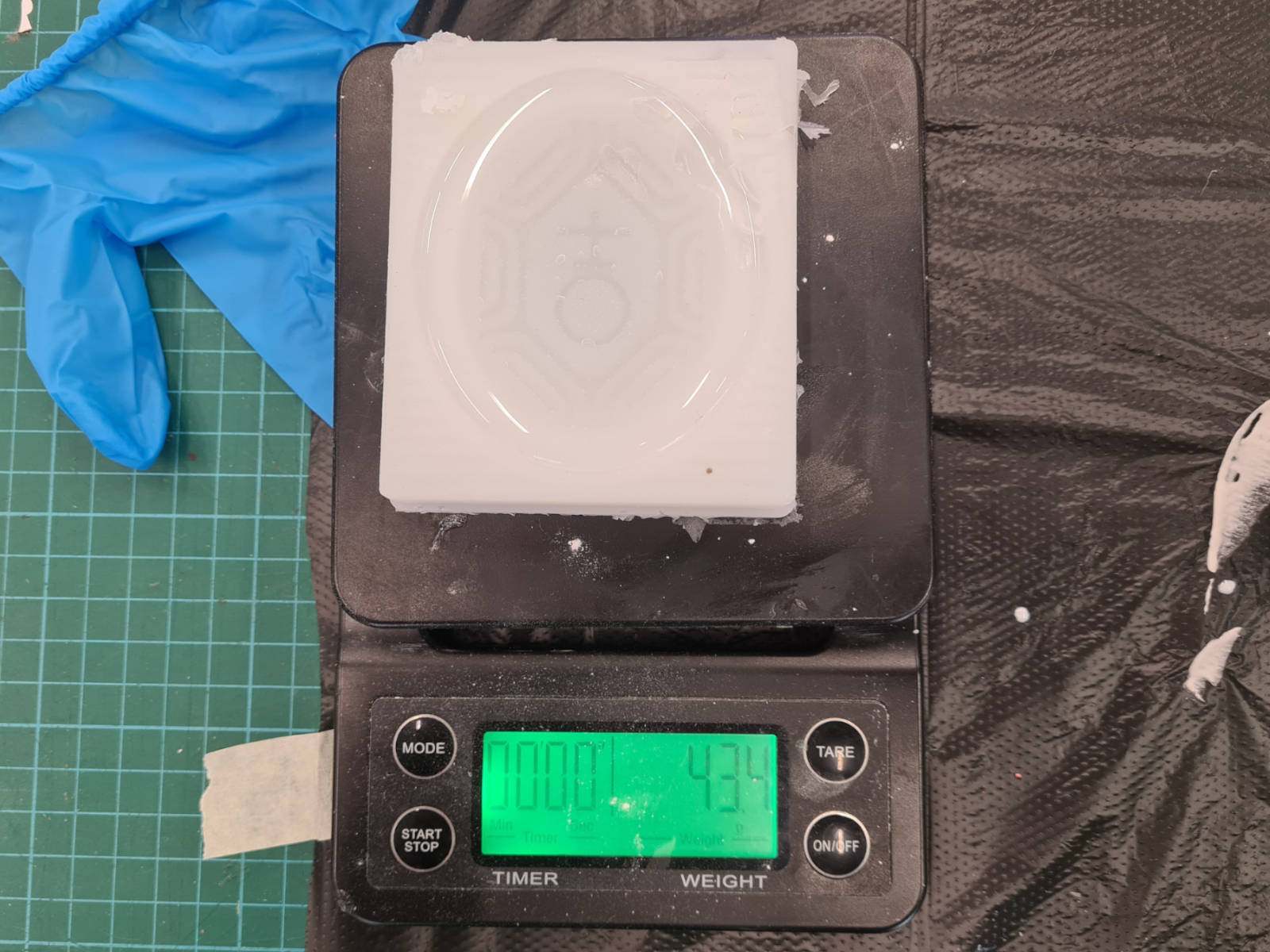
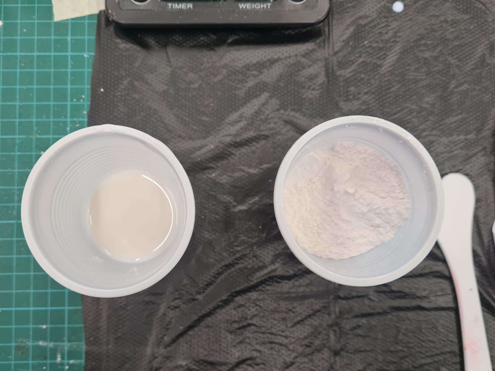 After measuring out the amount of powder and liquid, I added them together with two drops of red coloring.
 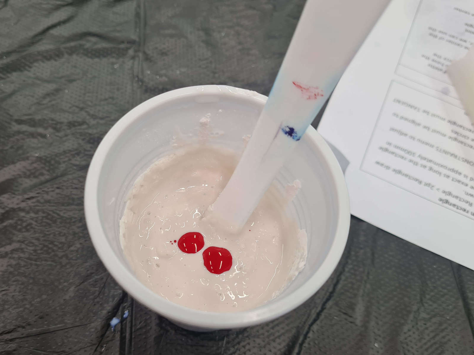 The mixture was then mixed evenly and poured into the mold. I found out that I actually prepared an twice of what I need (i.e. 44g liquid and 110g powder instead of 22g liquid and 55g powder).
Therefore, I poured the remainder into the spoilt mold, which I used to check whether the mixture had been set as I did not want to disturb the cast.
The mixture was then mixed evenly and poured into the mold. I found out that I actually prepared an twice of what I need (i.e. 44g liquid and 110g powder instead of 22g liquid and 55g powder).
Therefore, I poured the remainder into the spoilt mold, which I used to check whether the mixture had been set as I did not want to disturb the cast.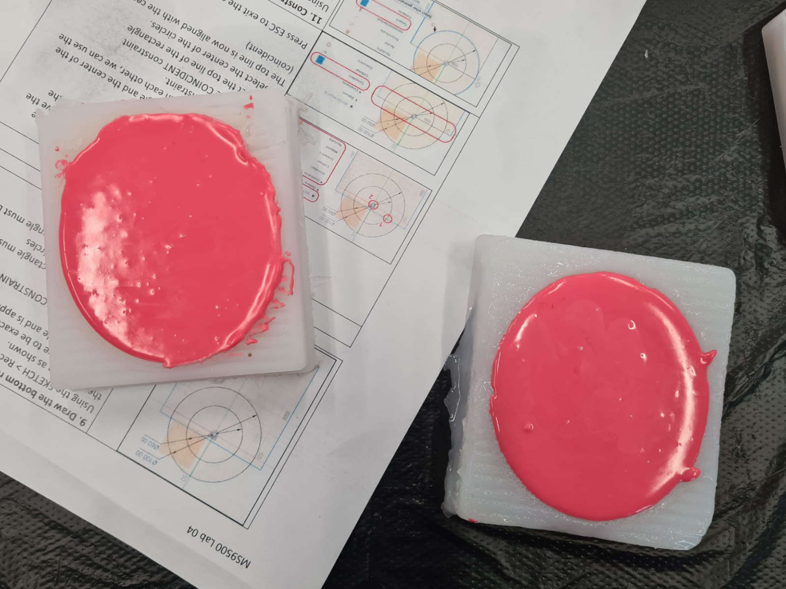 After two hours, the cast was already hardened. So, I first removed the cast from the spoilt mold and found it had been set.
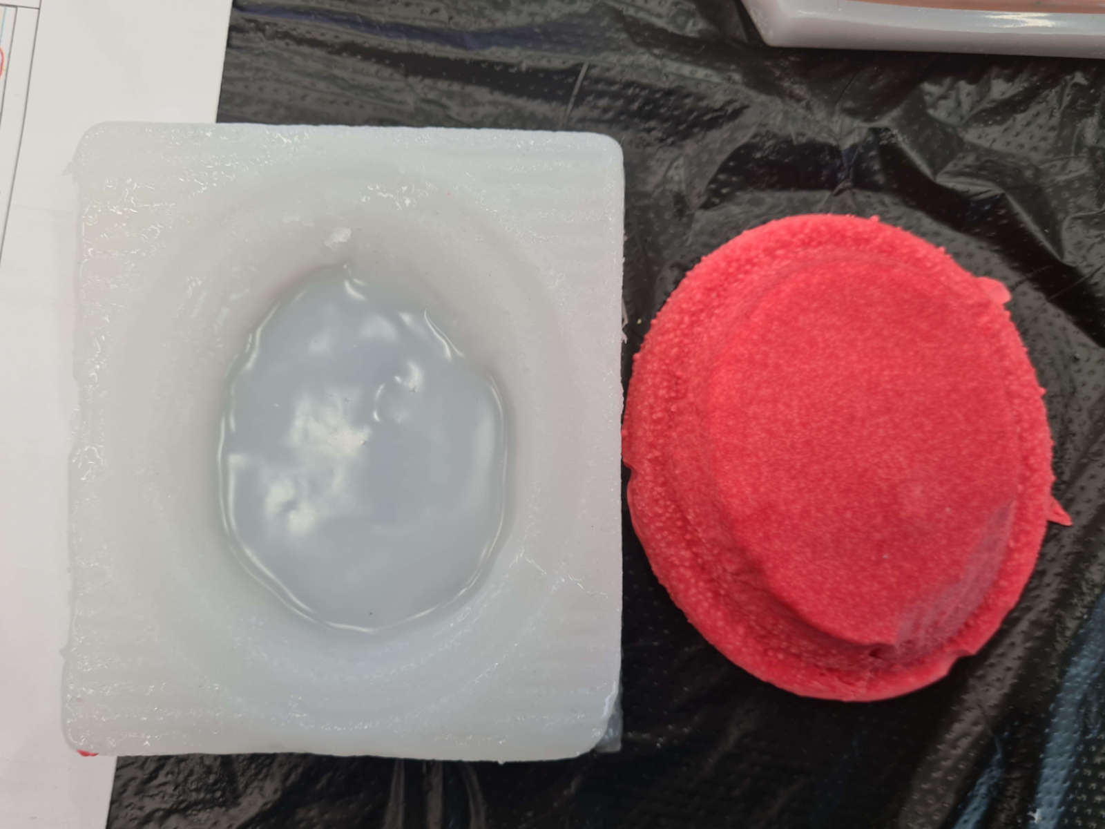 Therefore, I removed the cast from the actual mold to get the final cast product.
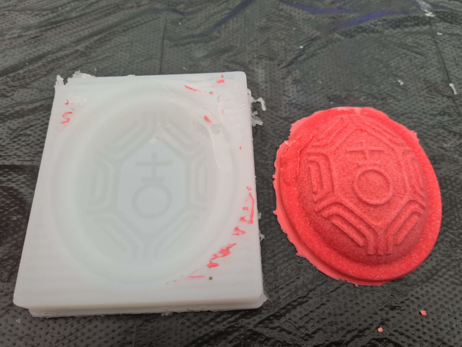 As a reflection, I find being meticulous and patient is the key for successful molding and casting. Even though the process is rather straightforward, attention to details is needed and the process cannot be rushed.