Week 4: Embedded Programming
Update
[25/02/23]- Group Assignment: Link to group assignment added.
- JavaScript coding of Micro:bit: Source code provided.
- Programming XIAO RP2040 to Communicate : updated the code and description.
Assignments
The assigments for this week are:Group Assignment
Compare the performance and development workflows for other architectures.
Individual Assignments
I. Browse through the data sheet for my microcontroller.
II. Program a microcontroller development board.
II. Program a microcontroller development board.
Compare Performance and Development Workflows for Other Architectures
This is a group assignment where we try out different development board and compare them. Each of us decided to try out a different development board. In my case, I was to try out coding Micro:Bit in JavaScript. The version of Micro:Bit I used was V1.5. Since I had previous experience with Micro:Bit, the coding interface was familiar to me. However, for those projects I made the code using the block coding. What is new for me was that this was the first time I used JavaScript to write code for a microcontroller. The code I created for this assignment is as below:
input.onButtonPressed(Button.A, function () {
    basic.showLeds(`
        # # # # #
        . . . . .
        . . . . .
        . . . . .
        . . . . .
        `)
    basic.pause(500)
    basic.showLeds(`
        . . . . .
        # # # # #
        . . . . .
        . . . . .
        . . . . .
        `)
    basic.pause(500)
    basic.showLeds(`
        . . . . .
        . . . . .
        # # # # #
        . . . . .
        . . . . .
        `)
    basic.pause(500)
    basic.showLeds(`
        . . . . .
        . . . . .
        . . . . .
        # # # # #
        . . . . .
        `)
    basic.pause(500)
    basic.showLeds(`
        . . . . .
        . . . . .
        . . . . .
        . . . . .
        # # # # #
        `)
    basic.pause(500)
    basic.showLeds(`
        . . . . .
        . . . . .
        . . . . .
        . . . . .
        . . . . .
        `)
})
As a reflection for this group assignment, I found JavaScript an interesting langauge and will like to learn more about it beyond just using it to code Micro:Bit. On the other hand, I found the Micro:Bit quite limiting in its' capabilites. It is a good tool for learning coding and basic electronics,
but is certainly not powerful enough for me to use it for my final project.
The full documentation can be found on the Group assignment page.
Browse Through the Datasheet of My Microcontroller
The microcontroller used for this assignment is the Seeed Studio XIAO RP2040. The datasheet for the RP2040 can be found on Seeed Studio's website. The first impression upon reading the datasheet is that it is easier to read than expected. The datasheet is not overly technical like other datasheets and is written plain English as much as possible. However, the datasheet is still full of technical information and has close to 650 pages, so reading the whole document is still a tedious task. I gather that the datasheet is not meant to be read from start to end and that it serve as a reference document for one to look up when certain information are needed. Therefore, I decide to run through the content pages to see what information might be relevant to me now. As the content pages are hyperlinked to the respectively chapters and sections, I was able to jump to the parts that I wanted to read about, making the browsing very convenient. As I do not have an electronics background, I was only able to understand very surface information and the chapter that I understood the most was Chapter 1 Introduction. From Chapter 1, I found out why the chip is called RP2040: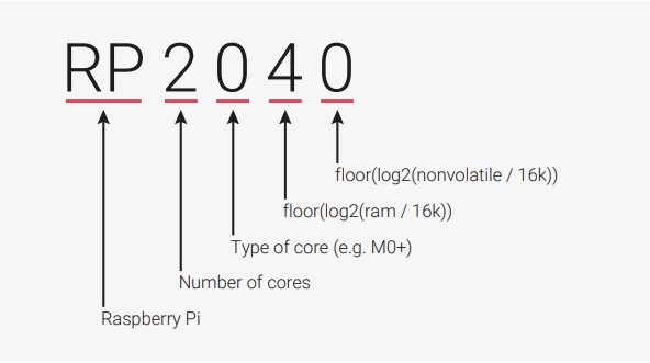 Next, I also found out the key features of the chip, such as:
- Dual Cortex M0+ processor cores, up to 133 MHz
- 264 kB of embedded SRAM in 6 banks
- 30 multifunction GPIO
- 6 dedicated IO for SPI Flash (supporting XIP)
- Dedicated hardware for commonly used peripherals
- Programmable IO for extended peripheral support
- 4 channel ADC with internal temperature sensor, 0.5 MSa/s, 12 bit conversion
- USB 1.1 Host/Device
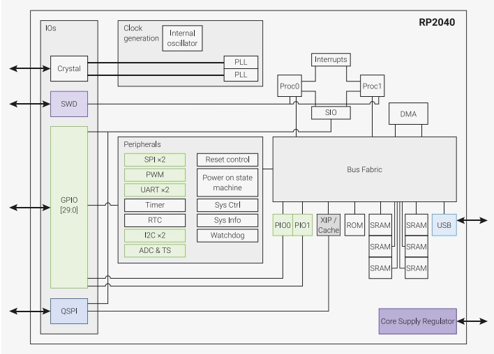
Other than those, I found the system overview of the RP2040 provided in the datasheet clear, event though I do not fully understand
all the component listed on it:- 264 kB of embedded SRAM in 6 banks
- 30 multifunction GPIO
- 6 dedicated IO for SPI Flash (supporting XIP)
- Dedicated hardware for commonly used peripherals
- Programmable IO for extended peripheral support
- 4 channel ADC with internal temperature sensor, 0.5 MSa/s, 12 bit conversion
- USB 1.1 Host/Device
 I am still somewhat able to understand the pin location figure and the accompanying pin descriptions in the section that follows. Beyong
that, the technical information are out of my grasp.
I am still somewhat able to understand the pin location figure and the accompanying pin descriptions in the section that follows. Beyong
that, the technical information are out of my grasp.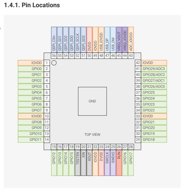 From Chapter 2 onwards, it was really getting quite challeging for me to understand the technical information provided.
Therefore, I quickly browse through them to have an idea what are being describe in each chapter. This is so that in the future
when I have a better understanding of the information and need to look them up, I know where to find them.
From Chapter 2 onwards, it was really getting quite challeging for me to understand the technical information provided.
Therefore, I quickly browse through them to have an idea what are being describe in each chapter. This is so that in the future
when I have a better understanding of the information and need to look them up, I know where to find them.
Program a Microcontroller Development Board
After reading the datasheet of Seeed XIAO RP2040, I used the Seeed XIAO RP2040 for the second part of the individual assignment, which is to write program for a microcontroller development board to interact and communicate.Setting Up The Arduino IDE
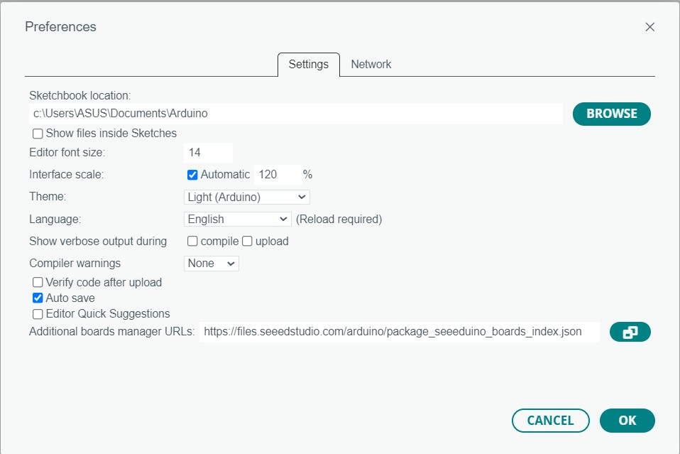
First, I downloaded and installed the lastest version of Arduino IDE (2.0.3) from the Arduino website. Then, following the instructions on the Seeed Studion website I set up the IDE for SeeeD XIAO RP2040, by navigating to File>Preference and adding the following URL to the Additional Board Managers URL:https://github.com/earlephilhower/arduino-pico/releases/download/global/package_rp2040_index.json
 Then, I navigated to the Board Manager (Tools > Board > Board Manager), searched for "RP2040" and installed the lastest version of Raspberry Pi RP2040 Boards.
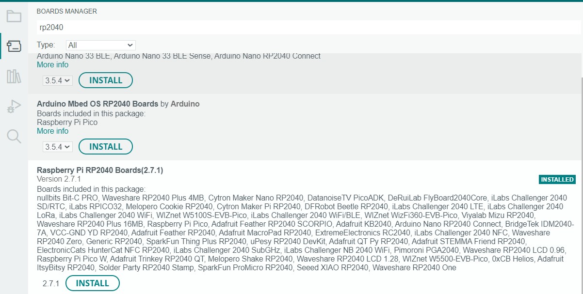 Additionally, I navigated to Sketch > Include Library > Manage Libraries... and searched for Adafruit_NeoPixel to installed the latest version of the neopixel library.
Programming XIAO RP2040 to Communicate
I attached a potentiometer and a circular LED strip to the XIAO board. Then, taking reference from the Adafruit Neopixel sketch, I wrote a program to control the speed of the LED strip color wipe using the potentiometer:// Adapted from Adafruit NeoPixel strip test program. // Written by Seh Yong, Leong //For Seeed XIAO RP2040 Board #includeAfter uploading the sketch to the board, the circuit worked as expected, albeit with a slight delay in the response.#ifdef __AVR__ #include // Required for 16 MHz Adafruit Trinket #endif // Which pin on the Seeed XIAO is connected to the NeoPixels? #define LED_PIN D0 // How many NeoPixels are attached to the board? #define LED_COUNT 8 // Declare our NeoPixel strip object: Adafruit_NeoPixel strip(LED_COUNT, LED_PIN, NEO_GRB + NEO_KHZ800); // Argument 1 = Number of pixels in NeoPixel strip // Argument 2 = Arduino pin number (most are valid) // Argument 3 = Pixel type flags, add together as needed: // NEO_KHZ800 800 KHz bitstream (most NeoPixel products w/WS2812 LEDs) // NEO_KHZ400 400 KHz (classic 'v1' (not v2) FLORA pixels, WS2811 drivers) // NEO_GRB Pixels are wired for GRB bitstream (most NeoPixel products) // NEO_RGB Pixels are wired for RGB bitstream (v1 FLORA pixels, not v2) // NEO_RGBW Pixels are wired for RGBW bitstream (NeoPixel RGBW products) // setup() function -- runs once at startup -------------------------------- void setup() { // These lines are specifically to support the Adafruit Trinket 5V 16 MHz. // Any other board, you can remove this part (but no harm leaving it): #if defined(__AVR_ATtiny85__) && (F_CPU == 16000000) clock_prescale_set(clock_div_1); #endif // END of Trinket-specific code. strip.begin(); // INITIALIZE NeoPixel strip object (REQUIRED) strip.show(); // Turn OFF all pixels ASAP strip.setBrightness(10); // Set BRIGHTNESS to about 1/5 (max = 255) } // loop() function -- runs repeatedly as long as board is on --------------- void loop() { int sensorValue = analogRead(A1); //read the value from the potentiometer // Fill along the length of the strip in various colors... colorWipe(strip.Color(255, 0, 0), sensorValue); // Red colorWipe(strip.Color( 0, 255, 0), sensorValue); // Green colorWipe(strip.Color( 0, 0, 255), sensorValue); // Blue } // Fill strip pixels one after another with a color. Strip is NOT cleared // first; anything there will be covered pixel by pixel. Pass in color // (as a single 'packed' 32-bit value, which you can get by calling // strip.Color(red, green, blue) as shown in the loop() function above), // and a delay time (in milliseconds) between pixels. void colorWipe(uint32_t color, int wait) { for(int i=0; i<strip.numPixels(); i++) { // For each pixel in strip... strip.setPixelColor(i, color); // Set pixel's color (in RAM) strip.show(); // Update strip to match delay(wait); // Pause for a moment } }
Programming XIAO RP2040 to Communicate
I wrote a simple sketch that allows me to type in a string from the laptop keyboard into the serial monitor with the board connected to laptop. The board then response by repeating what I wrote.
String a;

void setup() {
  Serial.begin(9600);
}

void loop() {

if(Serial.available()){
  a = Serial.readString();
  Serial.print("I am reading the word ");
  Serial.println(a);
}
}
The sketch worked as shown below:Design Files
The sketch file for the potentiometer/neopixel circut.The sketch file for string input via the serial monitor.