Week 3: Computer-Controlled Cutting
Updates
[08/03/2023]• Cut Something on the Vinylcutter - added settings for heat pressing.
• Laser Cutting - added optimal settings for material used (i.e. 3mm acrylic)
Assignments
The assigments for this week are:Group Assignment
Characterise the lasercutter.
Individual Assignment
I. Cut somthing on the vinylcutter.
II. Design, lasercut, and document a parametric construction kit.
II. Design, lasercut, and document a parametric construction kit.
Characterise the Lasercutter
For this group assignment, we are supposed to charaterise the lasercutter's focus, power, speed, rate, kerf, joint clearance and types. For that, I designed three templates: one to characterise the power and speed for cutting, one to characterise the power and speed when rastering, and one for characterising the kerf: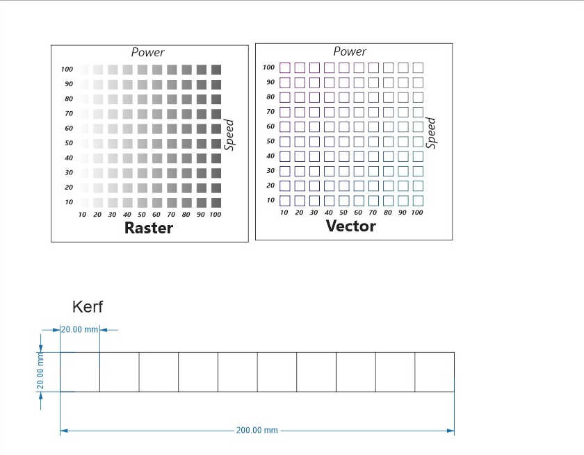 The templates were then handed to my course mates for laser cutting. The full documentation can be found on the
Group assignment page.
The learning points for me from this group assignment are:
The templates were then handed to my course mates for laser cutting. The full documentation can be found on the
Group assignment page.
The learning points for me from this group assignment are:
- 1) How to create a template for quick characterisation of the laser cutter.
- Initially, I wanted to use color mapping on the raster template to test the different raster settings individually. I later learned from the instructors that it is more efficient to use gradual fill across a group of settings. This allows the group of settings to be tested in a single submission by having the power to vary while holding the speed setting constant. My group mate also simplified the vector template from 100 settings to 25 settings by increasing the power/speed intervals of each settings. This allows for the vector settings to be tested quickly.
- 2) How to chracterise the kerf. Characterising the kerf allows me to make good press fit construction kit for the indiviual assigment.
Cut Something on the Vinylcutter
For this assignment, I used the Cricut Maker in the workshop.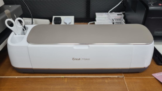 The software used was Cricut Design Space. After launching the software, I uploaded the chosen logo onto the canvas:
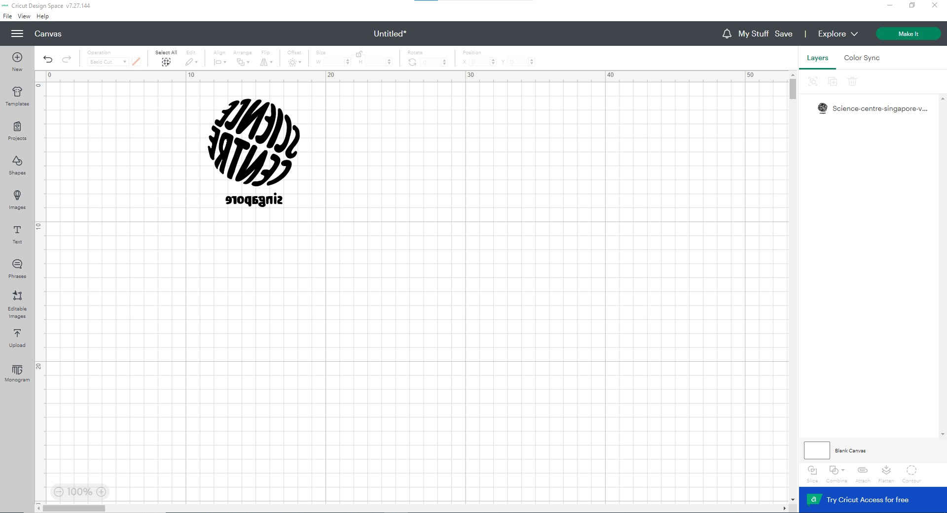 The logo was mirrored as I was going to use heat transfer vinyl with the adhesive side exposed to the blade. Next, I clicked on the make it button on the top left, I was directed to choose how do I want to load the material.
After indicating my choice of the mat, I then come to the mat layout interface as below:
The logo was mirrored as I was going to use heat transfer vinyl with the adhesive side exposed to the blade. Next, I clicked on the make it button on the top left, I was directed to choose how do I want to load the material.
After indicating my choice of the mat, I then come to the mat layout interface as below: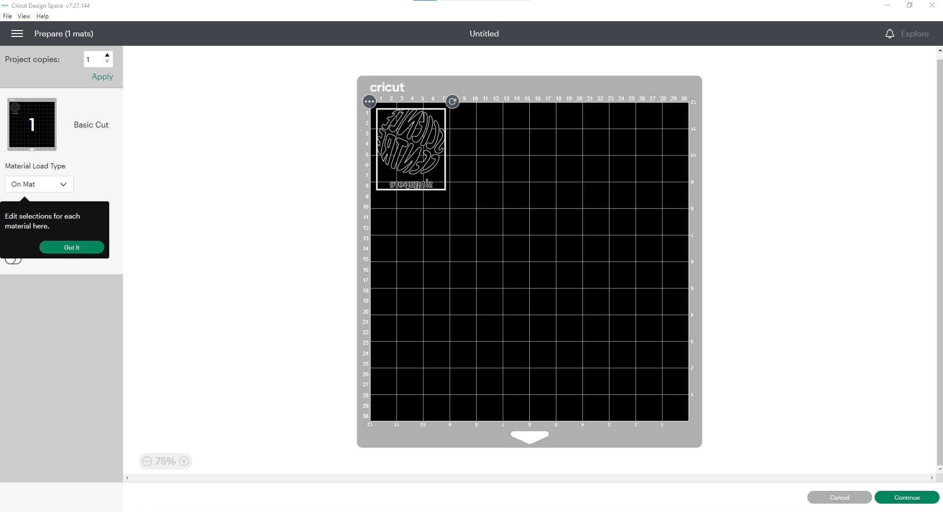 As I was quite satisfied with the position of the logo on the mat, I procceeded by clicking on continue on the bottom left. Then, after the software detects the Cricut Maker (which was connected to the computer via USB), I have to set
the base material. I selected Browse All Materials on the right of the material selection and did a quick search to find the material I want, i.e., Heat Transfer (non-Cricut).
As I was quite satisfied with the position of the logo on the mat, I procceeded by clicking on continue on the bottom left. Then, after the software detects the Cricut Maker (which was connected to the computer via USB), I have to set
the base material. I selected Browse All Materials on the right of the material selection and did a quick search to find the material I want, i.e., Heat Transfer (non-Cricut).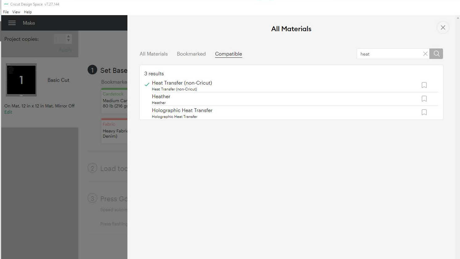 With the material selected, what is left is to select the blade presssure, load the material and start the cutting. For these, I followed the instruction of the screen.
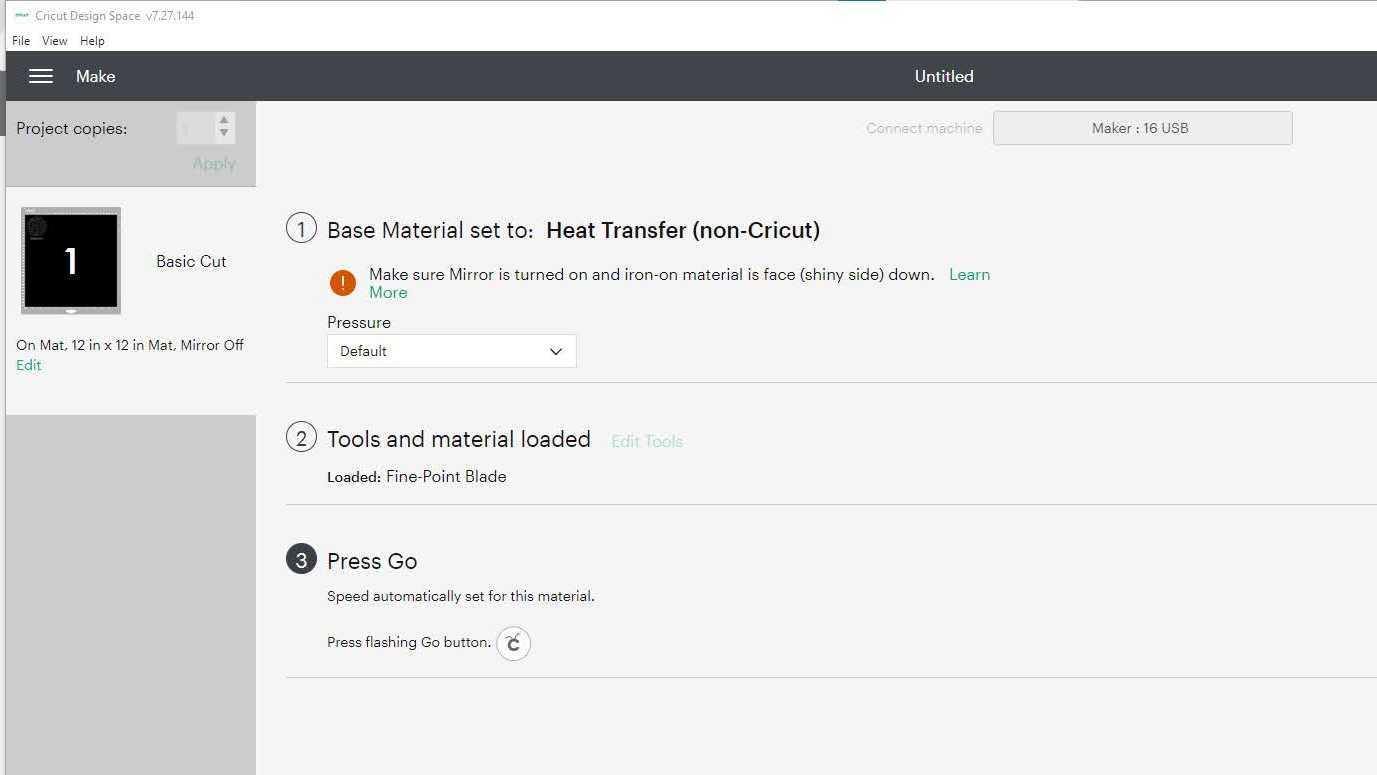 I chosen default pressure as the cut pressure settings for the eat Transfer (non-Cricut)material had already been set to the lowest. After I press Go on the machine, the cutting began:
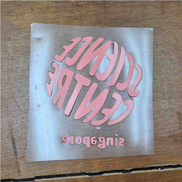
After the cutting was completed, the vinyl was unloaded from the vinyl cutter. I then cut out the portion with the logo and weeded out the unwanted vinyl.
 The press that was used was the Cricut EasyPress 2, which was set to the condition for the heat pressing (i.e. 165℃ for 30 seconds).
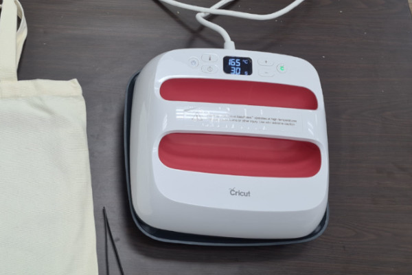 The weeded vinyl was then heat pressed onto a canvas tote bag to give the final product.
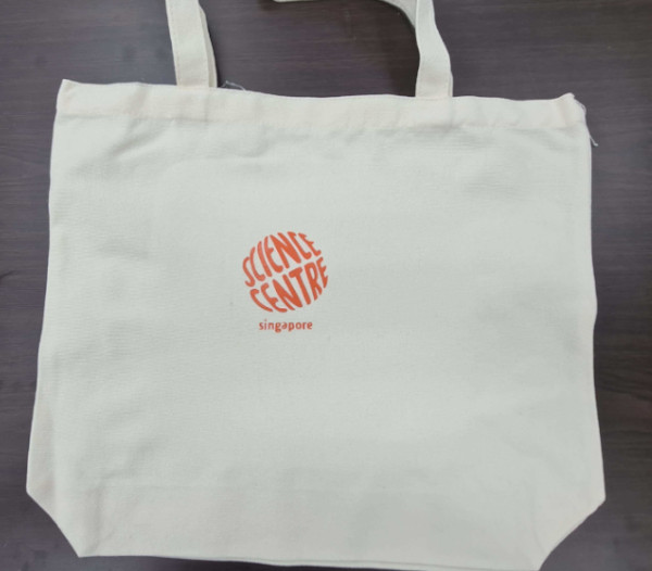
Design, Lasercut, and Document a Parametric Construction Kit
I had previously came across the Puzzle Wine Rack by Gideon Dagan. Inspried by the wine rack design, I decided to design something similar for the parametric construction kit.Designing The Kit
The construction kit was created in Fusion 360. The shape of the kit was modelled after the puzzle wine rack. However, instead of the curvy outline like the wine rack, the construction kit had straight edges and filet corners: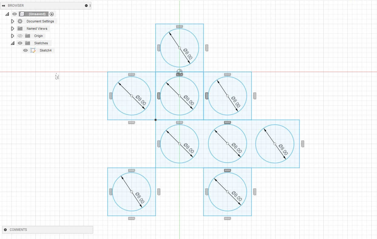 To make the design parametric, the Change Parameter tool was used, which can be found under the Modify tab.
I created some user parameters to make it easy both to find the values of the respective dimension and to key in the expression for the model parameters. The model parameters are also renamed to make it easy to identify the individual parameter:
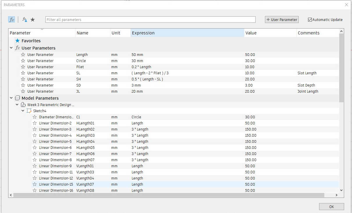 The list of parameter is rather long and I could have use more of the equal constraint to make the parameter list shorter and simpler.
Nonetheless, I tested the parameters and it worked:
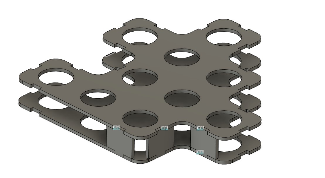
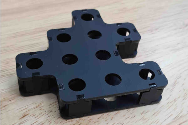
The Puzzle Wine Rack was fabricated using ABS and assembled with dowels. For my construction kit, I decided to use press fit plates instead. Before I proceed to do the actual laser cutting, I did a assembly simulation in Fusion 360 to check everything is in order:
 The design was then expoerted as DXF file and ready for laser cutting.
Laser Cutting
Since there are a sizable amount of waste acrylic sheets in the workshop, I decided to fabricate my construction kit using the waste acrylic.The laser cutter was characterised as per the group assignment. The optimal settings for the 3mm acrylic used was determined to be:
• Speed - 15%
• Power - 85%
• Frequency - 5000 Hz After that, the DXF file of the construction kit was imported into Coreldraw on the laptop that was connected to the laser cutter. Using Coreldraw, the dimension of the design was first offset by 0.9mm to account for the kerf, and then submitted to laser cutter for cutting: After laser cutting was completed, the pieces were assembled. The joints fitted well to give an unit of the construction kit:
Assembly
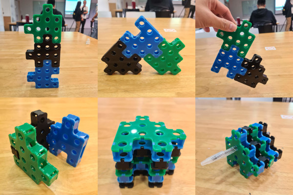
Two more units of the construction kit were produced by laser cutting. The kits were able to be assembled in different ways with fitting joints.The construction kit units can also be combined together to give one single "lattice" structure, which can then be used to hold objects (e.g. pens):
Design Files
Fusion 360 file of the construciton kit.DXF file of the construction kit.