This week we have been introduced to the process of milling our boards. But for it, we learn how to set up our Lab Milling or CNC machines and prepare the files to do it.
Before Milling it is very important to prepare de files in G-code for the different types of End Mills and setting we will be using, as a general rule we have this base:
The file of Drill and Outline can be both together as they have the same settings, but just to have more control we separate the files just in case we want to change the drills, especially when we have big pins the End mill has to be bigger.
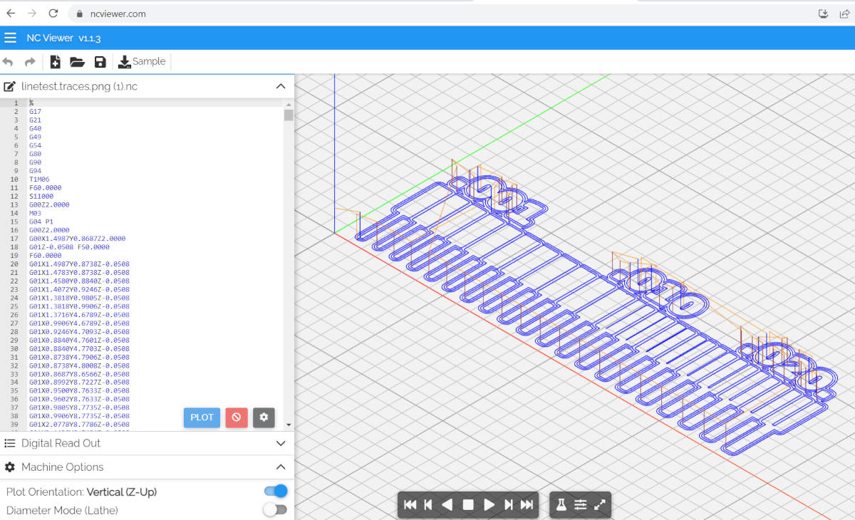
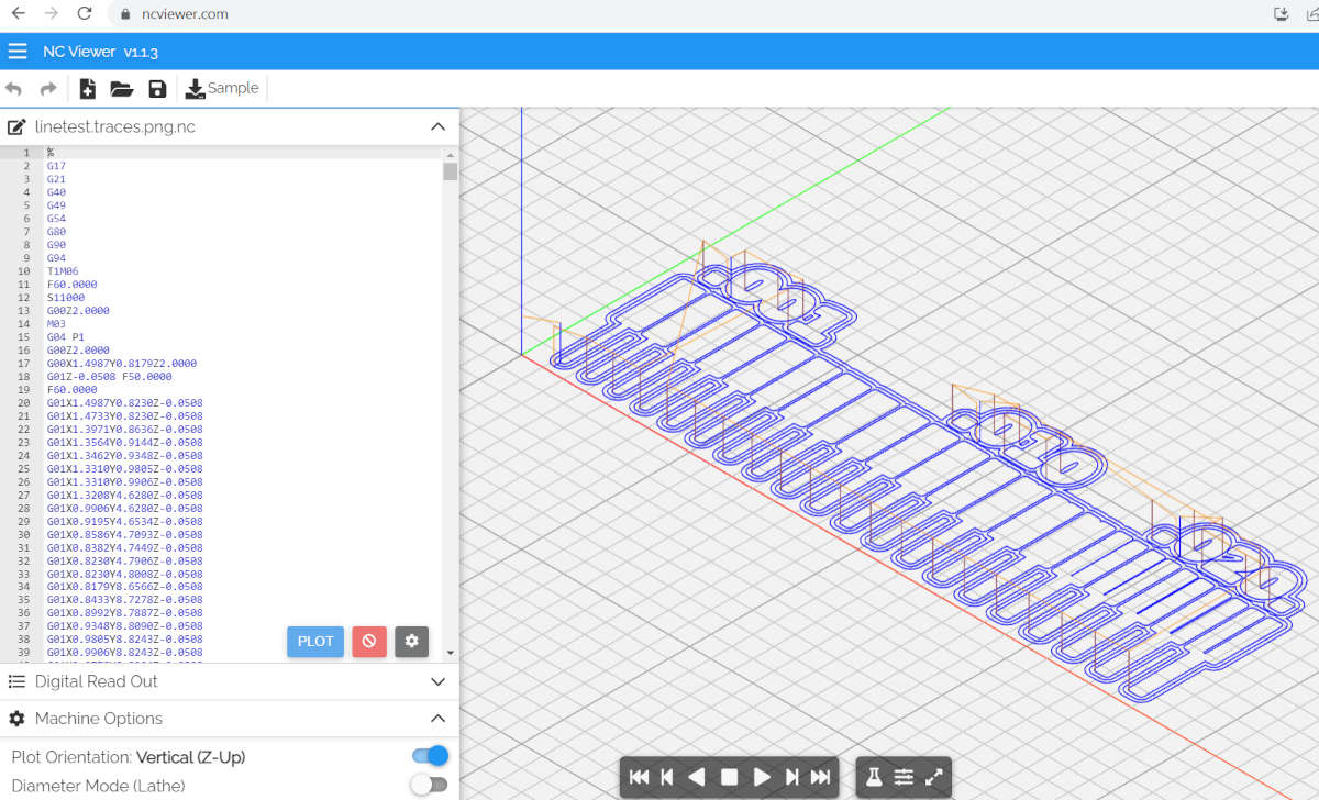
We create the G-Code in Mods as documented on our pages. When we have the files ready we move to the CNC computer and open the files, the first to be milled are the traces, then the drills, and lastly the Outline.
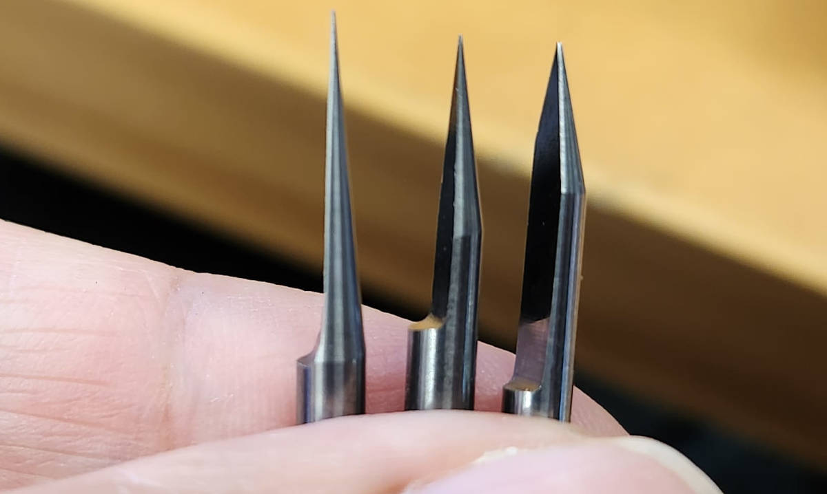
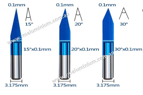
We have to find the optimal speed trace resolution and the size of the End mill for each task. For the traces our lab uses, in general, the V-bit in 0.1mm there are three angles, 10, 20, and 30. These angles influence the thickness of the trace, the deeper that we go with it the thicker the trace becomes.
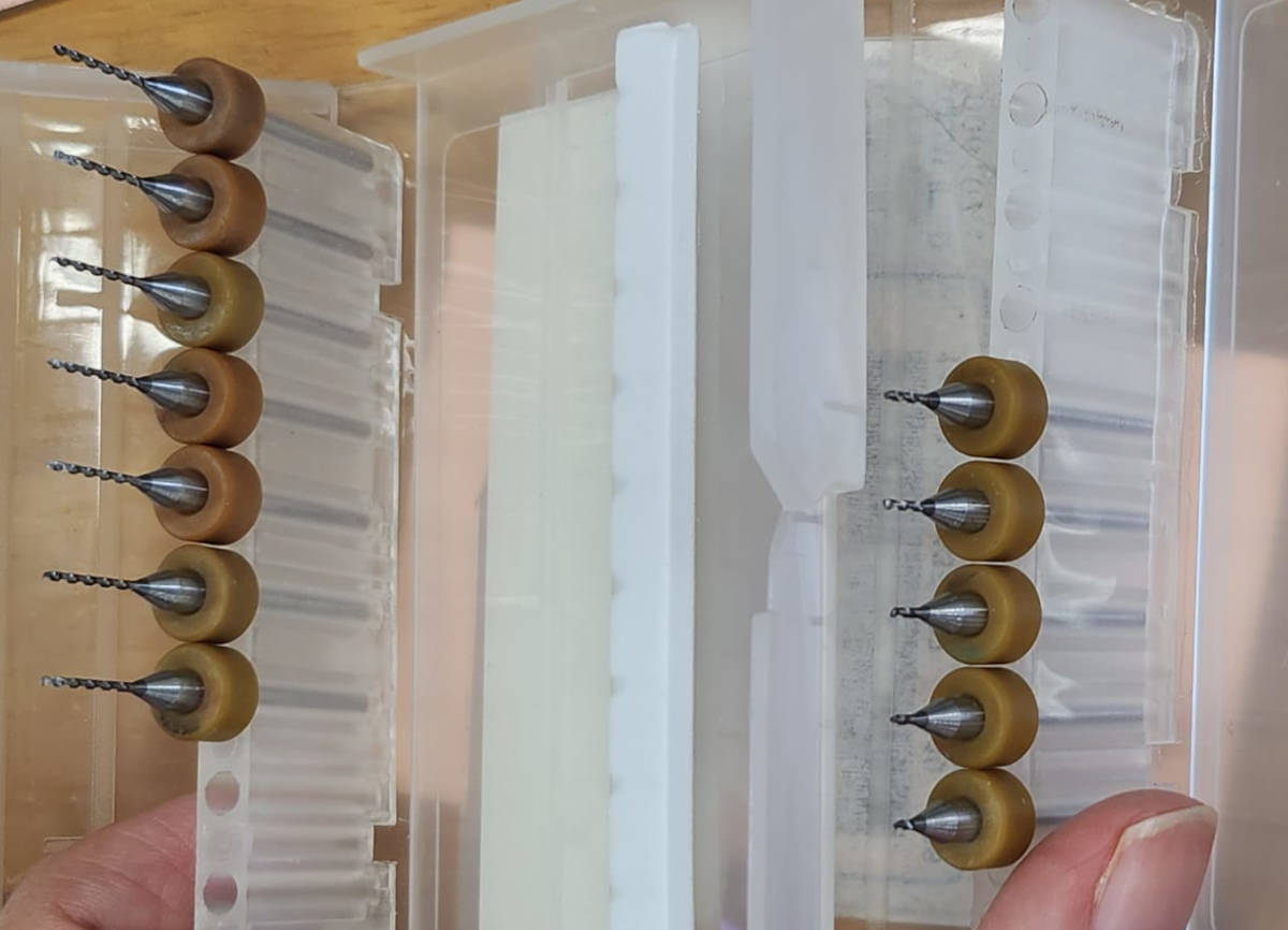
For the End Flat Mills, the 4mm and 3mm are generally used for the traces and to cut the Outline we use the 0.8mm. Steven cuts the End mill a bit, when they are left longer, they are more prone to break.
We have a CNC Stepcraft-UCCNC machine in our lab, it is very versatile as it is a desk/table machine.
We prepared the sacrificial bed making sure it is leveled and clean.
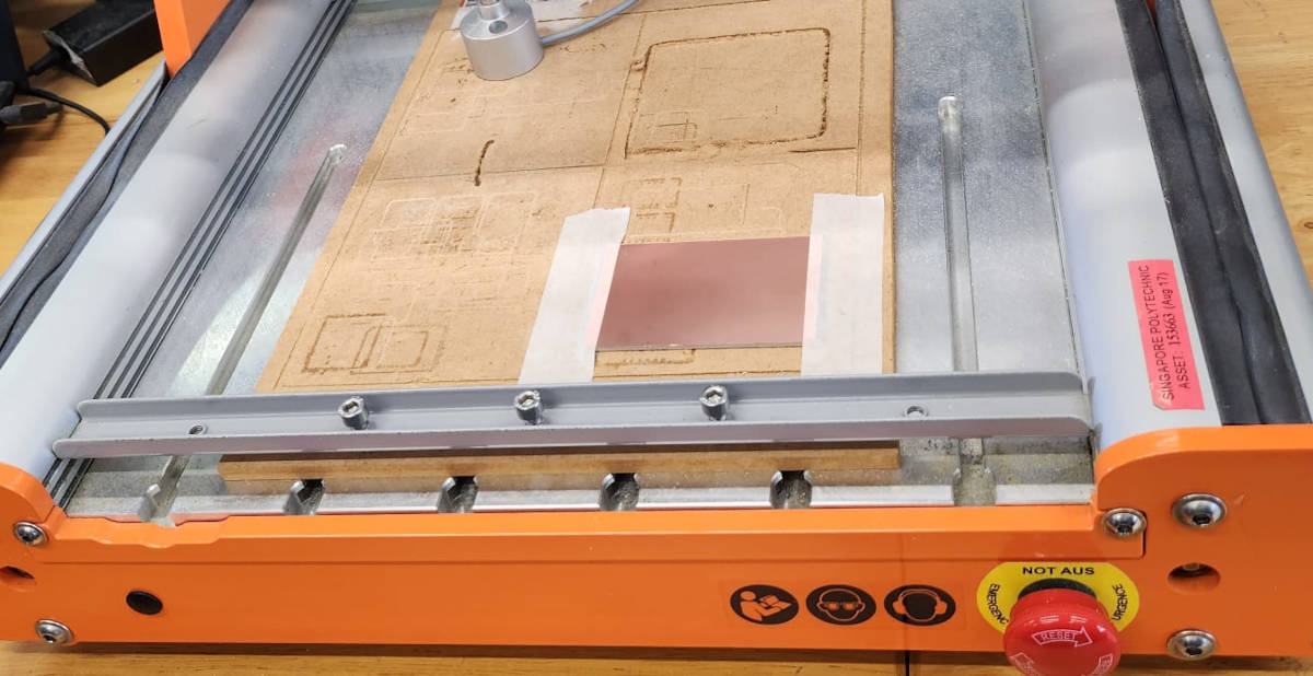
Put some double-faced tape at the back of the PBC board (cutting with scissors) to avoid bumps and stick the board into the bed.
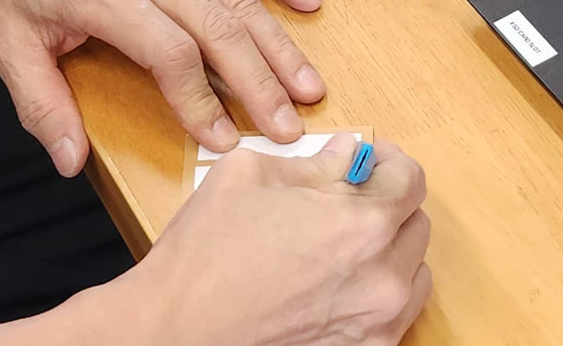
We double-secure the board with masking tape, all to make sure the board doesn't move through the milling process.
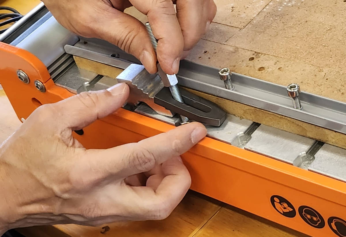
We have to screw the End mill into the CNC being very careful not to break it or injure ourselves as they are very sharp and pointy. The Collets have a specific size for each End Mill so we have to choose accordingly.
Then we are ready to set up the file with the program, in our Lab we use the software Stepcraft, and we do the following steps:
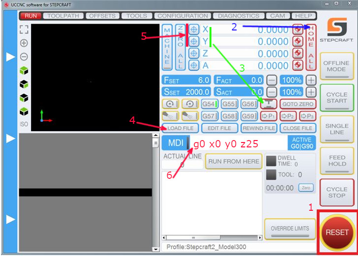
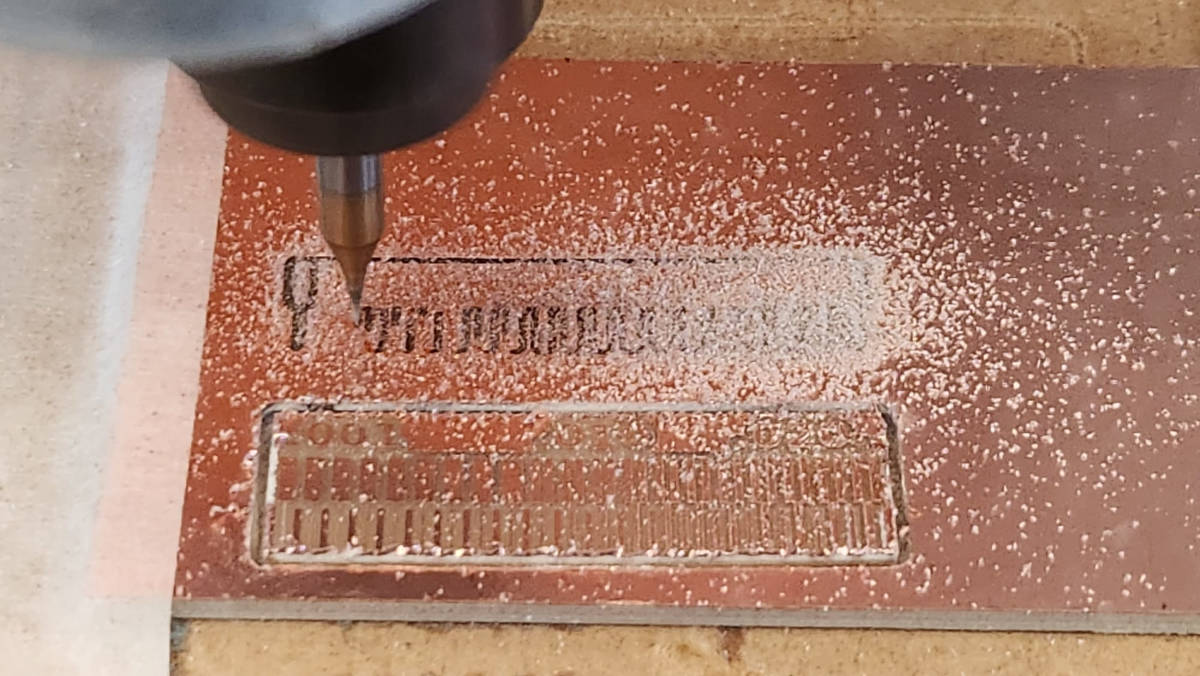
When we are ready Puch the Cycle Start Button and the machine starts the milling process.
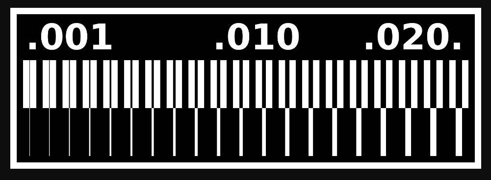
We have done two samples to try the mills for the “Traces sample” in V-Bit of 0.1 mm and the other with a 0.4 mm flat End Mill. We wanted to compare their finish with the same settings.
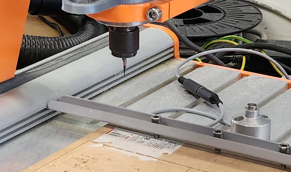
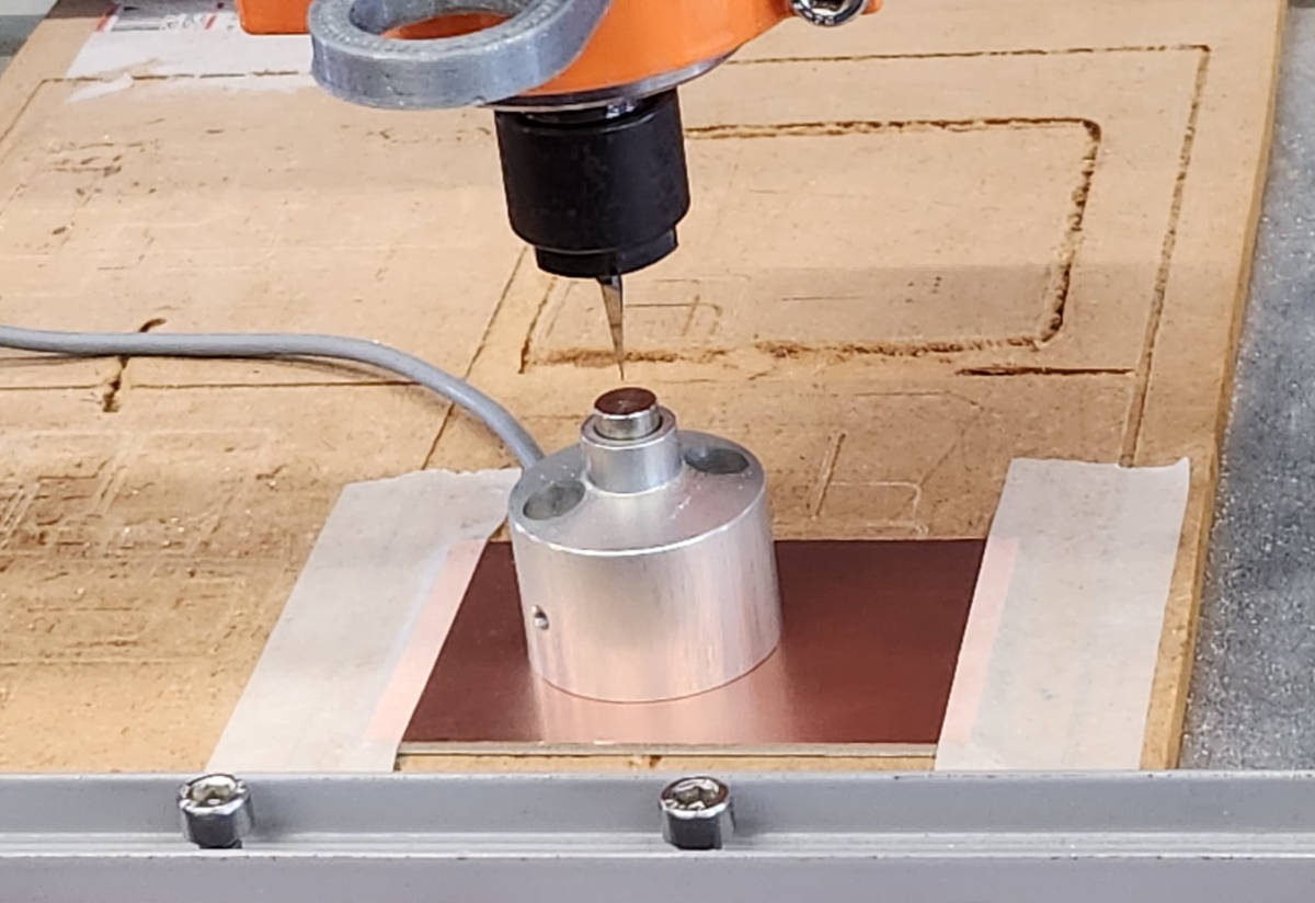
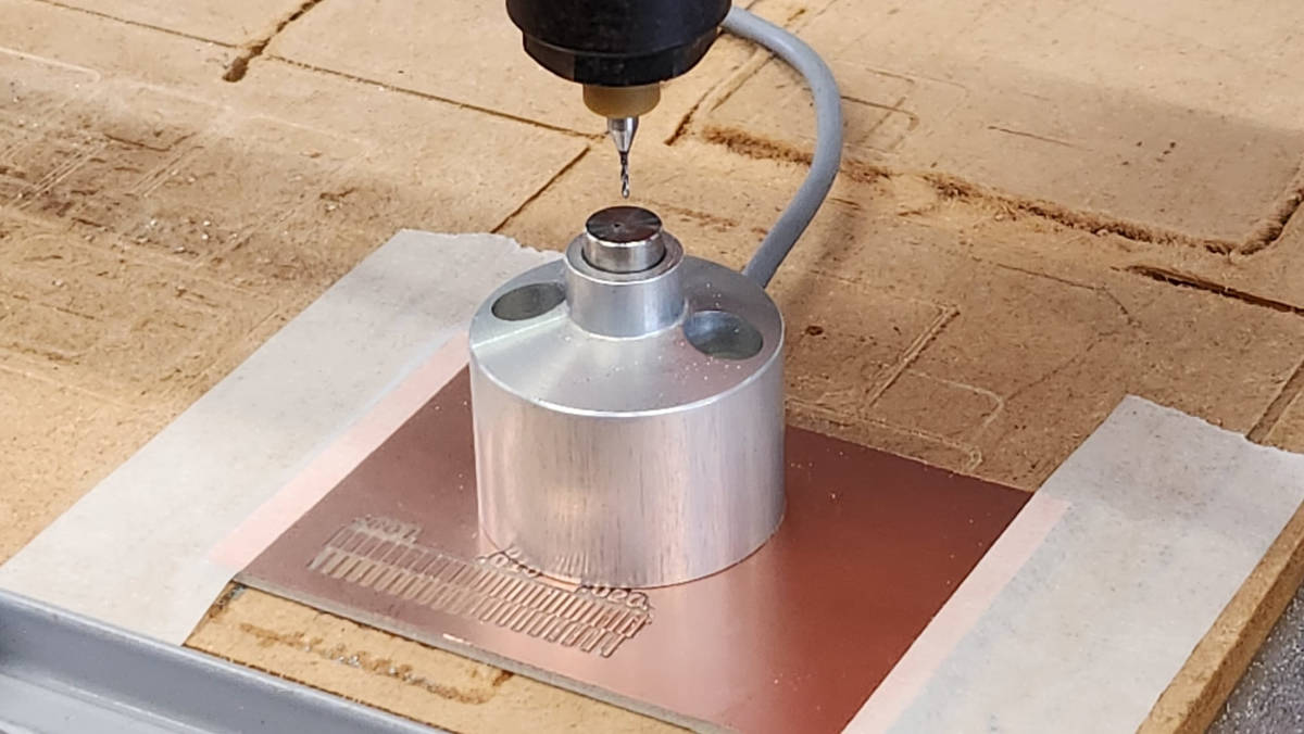
Always we change an End mill we have to repeat the process of finding the real Z-zero point but we leave the X and Y points as they are, so the milling starts in the same place when we do the Outline.
When milling the second “Traces sample” we changed the End Mill, but this time we changed the zero starting point where we needed to start again.
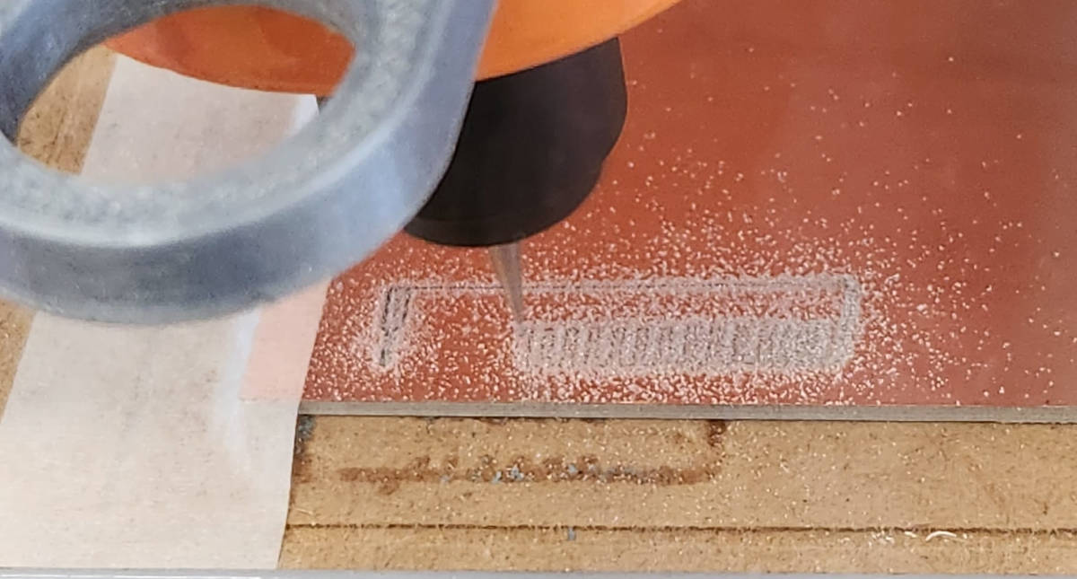
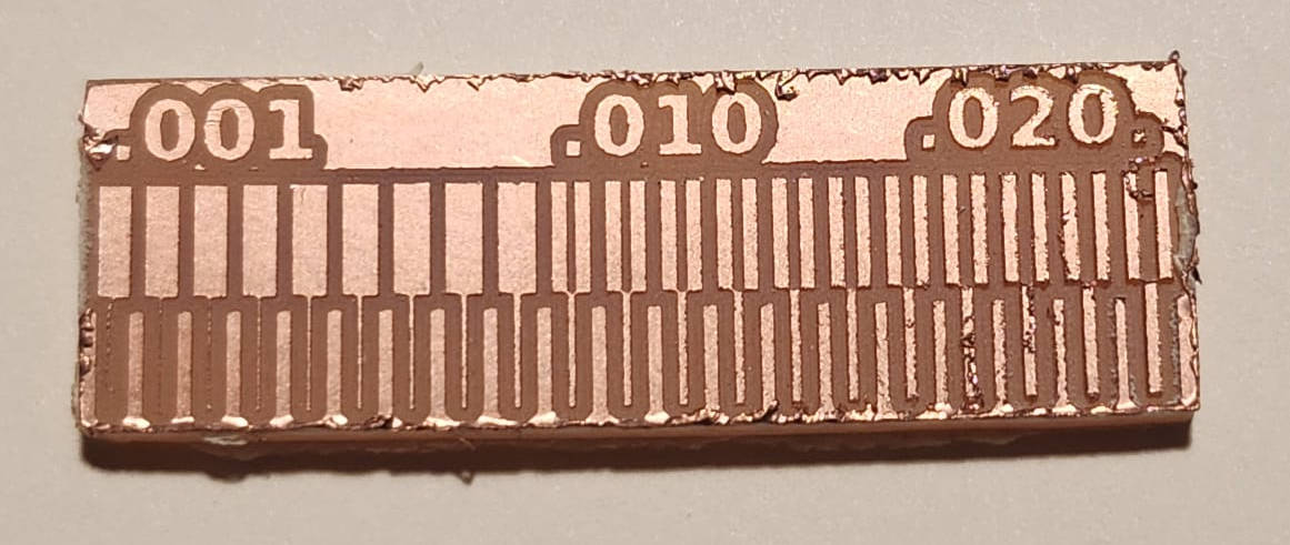
The result without sanding for the Traces milled with the V-Bit where much clear and neat. And with the Flat End Mill was of very bad quality, and the details were really bad.
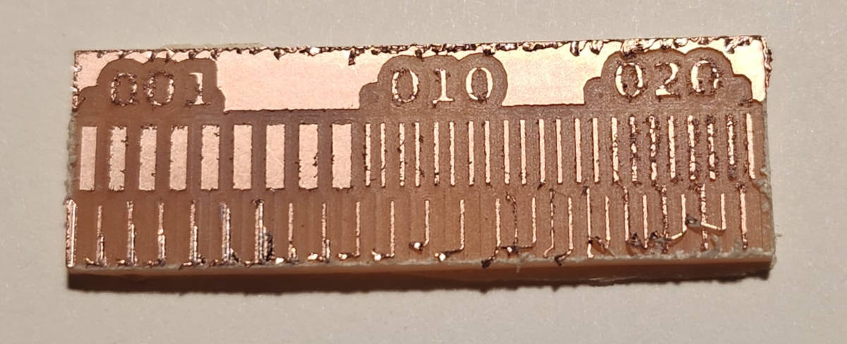
As the results of the milling were not as expected, the flat end mill shouldn't ve given that poor result, and because some other students have not really good results with their milling either, Steven decided it was time to resurface the sacrifitial layer of the CNC and put a new 0.4 flat endmill and try to do the sample again.
This time we tried in Mods the setting of 0.3mm and 0.4mm flat endmills, but milling both of them with a 0.4mm endmill.This is the result
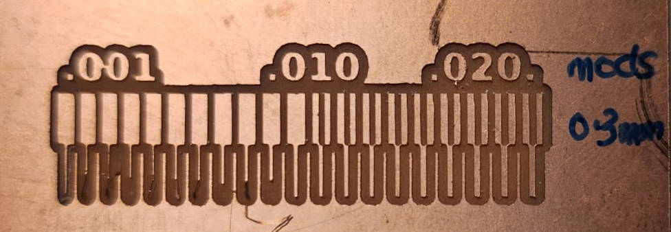
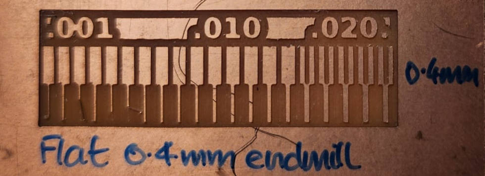
We could say the first sample of the 0.4mm flat endmill is not valid as it seems the Sacrifitial has to be resurfaced and the endmill we used was too wornout. At the second sample the results were more expected.
reviewing the sample of the V-bit 0.1mm end mill we could say it gives prett good results, and it can be used when we want to have the lines as thin as possible. The sample of the 0.3mm set in mods but milling with 0.4mm flat end mill gave quite good results, the lines where pretty clear until .012. The sample with mods setting of 0.4mm with the same 0.4mm flat endmill gave pretty good recults although the lines were more clear around the 0.16mm.
we could say that the 0.4mm flat end mill can be used when we want thicker traces, if we dont have a V-Bit, and we only have the 0.4mm flat endmill we can get better resolution and going a little bit finer with the lines when we change the setting in Mods, filling 0.3mm for the flat mill but instead milling with the 0.4mm.