W14. NETWORKING AND COMMUNICATIONS
We attempted to establish an I2C BUS Communication between us by using Arduino UNO Microcontrollers. To guide us on how to accomplish this, we followed tutorials from Aranacorp and Instructables, which we found online.
It's worth noting that throughout this writing process, we referred to the "Master" board as the "Mainboard", and the "Slaves" boards as "Peripherals".
This Doppler RADAR module supports repeat triggers and a 360-degree detection area with no blind spot; the best sensitivity is the component side.
Supports: Output On-Off, with adjustable repeat trigger time and detecting distance by adding the SMD components to the corresponding Pads.
The input Voltage is 4-28 VDC, it can detect movement in a range of 7m.
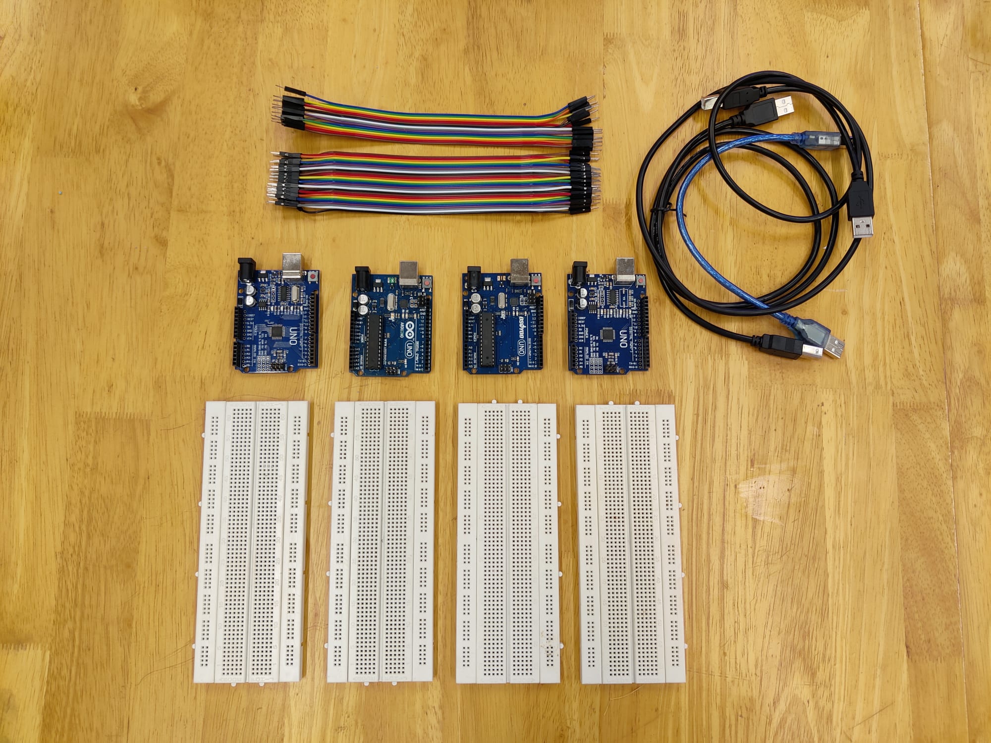
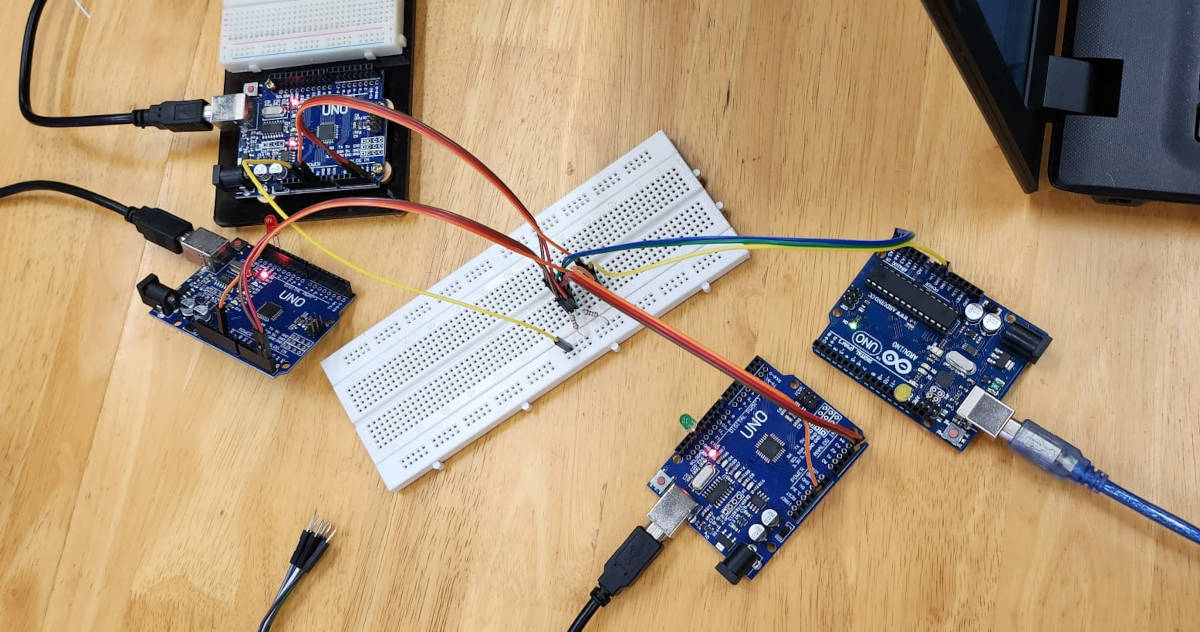
To set up the communication, we needed four Arduino UNO boards - one Main board (for giving the orders) and three Peripheral boards (for receiving the orders), and four laptops. We also used a common Breadboard to connect all of the Microcontrollers with jumpers.
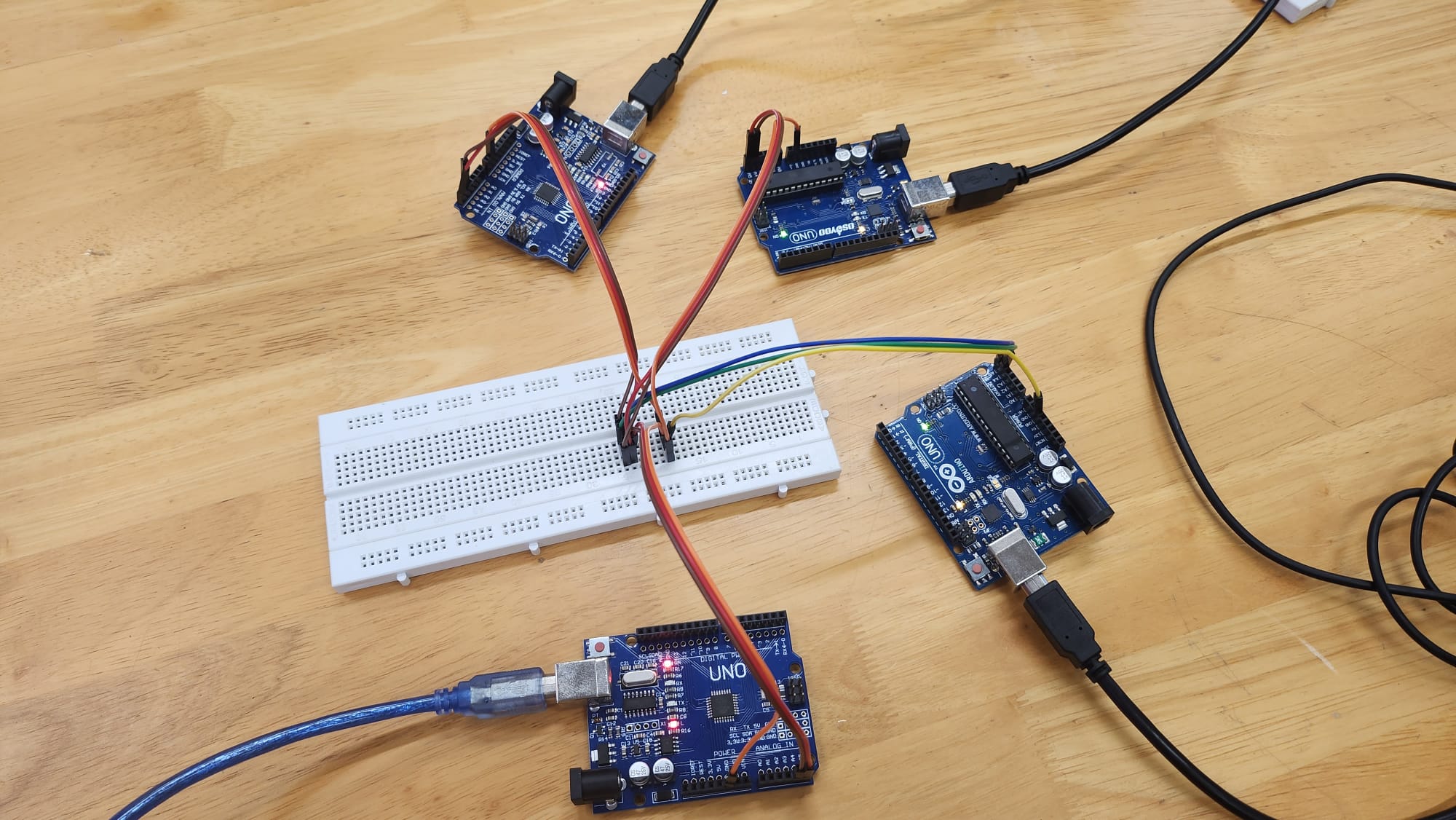
Afterward, we connected the Peripheral boards to the Main Board using jumpers. To do this, we utilized the pins A4 (SDA) and A5 (SDL), ensuring that we always connected A4 to A4 and A5 to A5 between the boards. We also made sure to connect all the boards from Ground to Ground for proper communication.
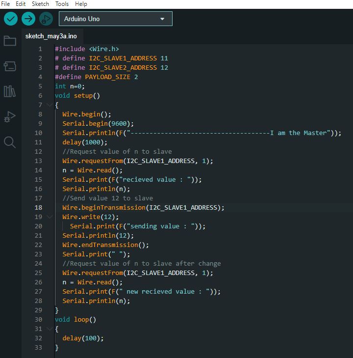
We used the Codes for the Mainboard and peripherals from the Tutorial of Aranacorp.
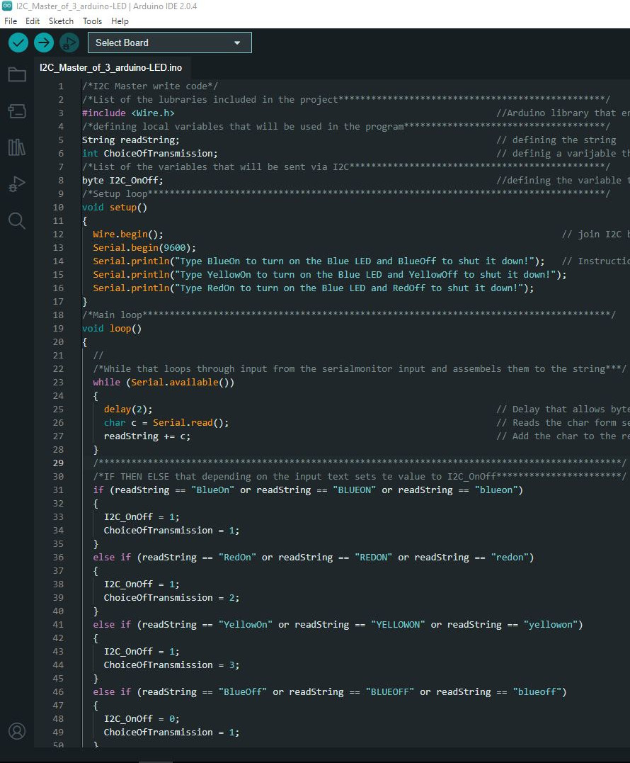
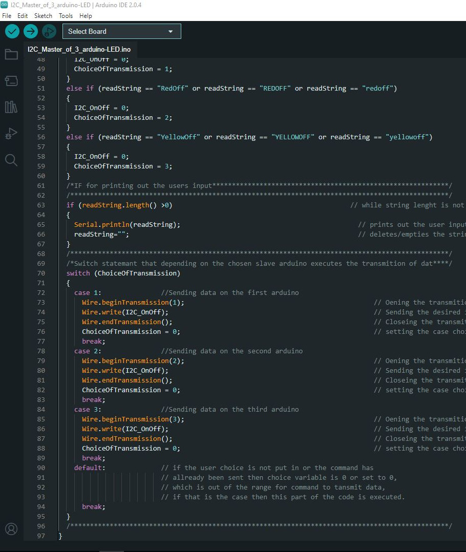
Mainboard (Master) Code
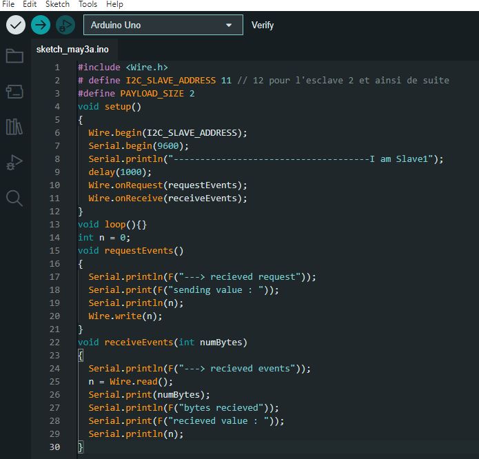
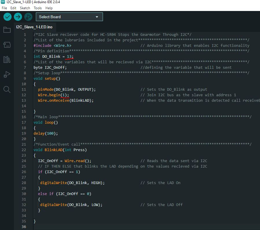
Peripheral (Slaves) Code
However, we encountered issues with the code as it did not work properly. We discovered that some computers were having difficulty connecting with certain microcontrollers, and also found that one of the microcontrollers was faulty. Additionally, we realized that two of the computers had USB restrictions that prevented them from connecting to a network protocol.
To address these issues, we replaced the faulty microcontroller and switched to different computers that did not have USB restrictions.
After encountering difficulties with the original code, we decided to switch to a different code for establishing a network connection. We used the codes provided in the “Autodesk Instructables” tutorial instead.
These codes were for the Master board to issue commands to the Peripheral boards, instructing them to turn on and off an integrated light.
To program the Peripheral boards, we specified the pin that we wanted to use for the integrated light, which in this case was Pin D13 for all of the boards. Additionally, we assigned a unique address to each Peripheral board, using the values 1, 2, and 3 respectively. The following code is an example for Peripheral board number 1, where we programmed it to use Pin D13 for the integrated light:
Once we had connected all the boards and uploaded the programs to each of them, we attempted to establish communication between them. However, we discovered that the setup wasn't working as expected.
While troubleshooting the issue, we thought that the connections between the boards were established properly. But, when the Main Board attempted to send an instruction to turn the LED Light on or off in one of the peripherals, nothing happened.
Unfortunately, we were unable to resolve the issue during our initial attempt. However, we planed to meet up again to further investigate the problem and work towards establishing a successful I2C BUS network connection.
We met and resumed the cable connections. During this process, we identified two errors from the previous attempt:
- We omitted to integrate the Pull Up 4.9K resistors in the I2C Bus system, which is essential for its proper functioning. We should have one resistor linked from the SDA line to the 5V line, and another from the SCL line to the 5V line.
- We didn't connect a jumper from the 5V pin of the Main Board to the Breadboard.
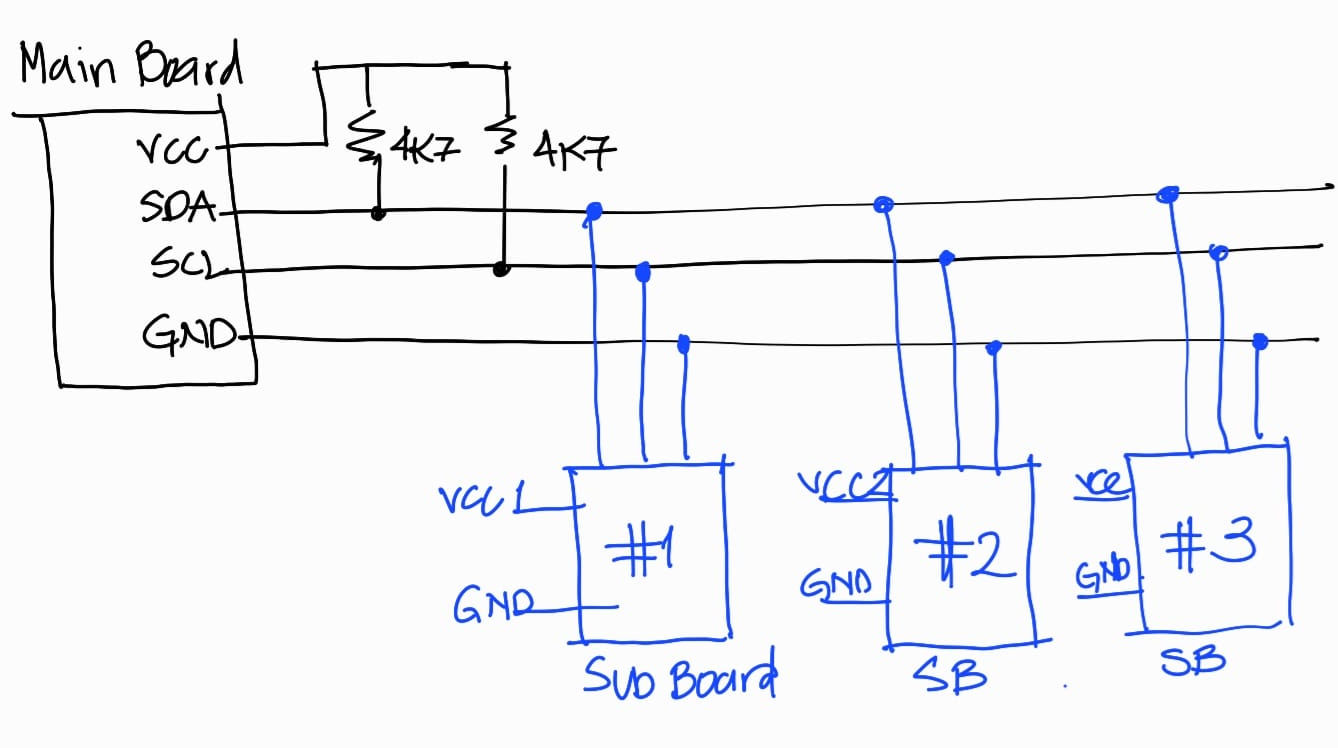
Making this changes the I2c Bus conection worked, using the same code shown above the Main Board could ask the sub Boards to turn on or off the LED lights we have put into each board. See in the video below.