Week 3: Computer-Controlled Cutting
Group Assignment
- characterize your lasercutter's focus, power, speed, rate, width, joint clearance and types
Individual Assignment
- Design, lasercut, and document a parametric construction kit, accounting for the lasercutter width,which can be assembled in multiple ways
- Cut something on the vinylcutter
WEEK 3 WORK ORGANIZATION
Group Assignment
The group assigment link is available here and the following is some additionalpoint to be considered when working with our lab laser cutter which is epilpg mini 40 watt
Characterize your Lasercutter's Focus, Power, Speed, Rate, Width, Joint Clearance and types
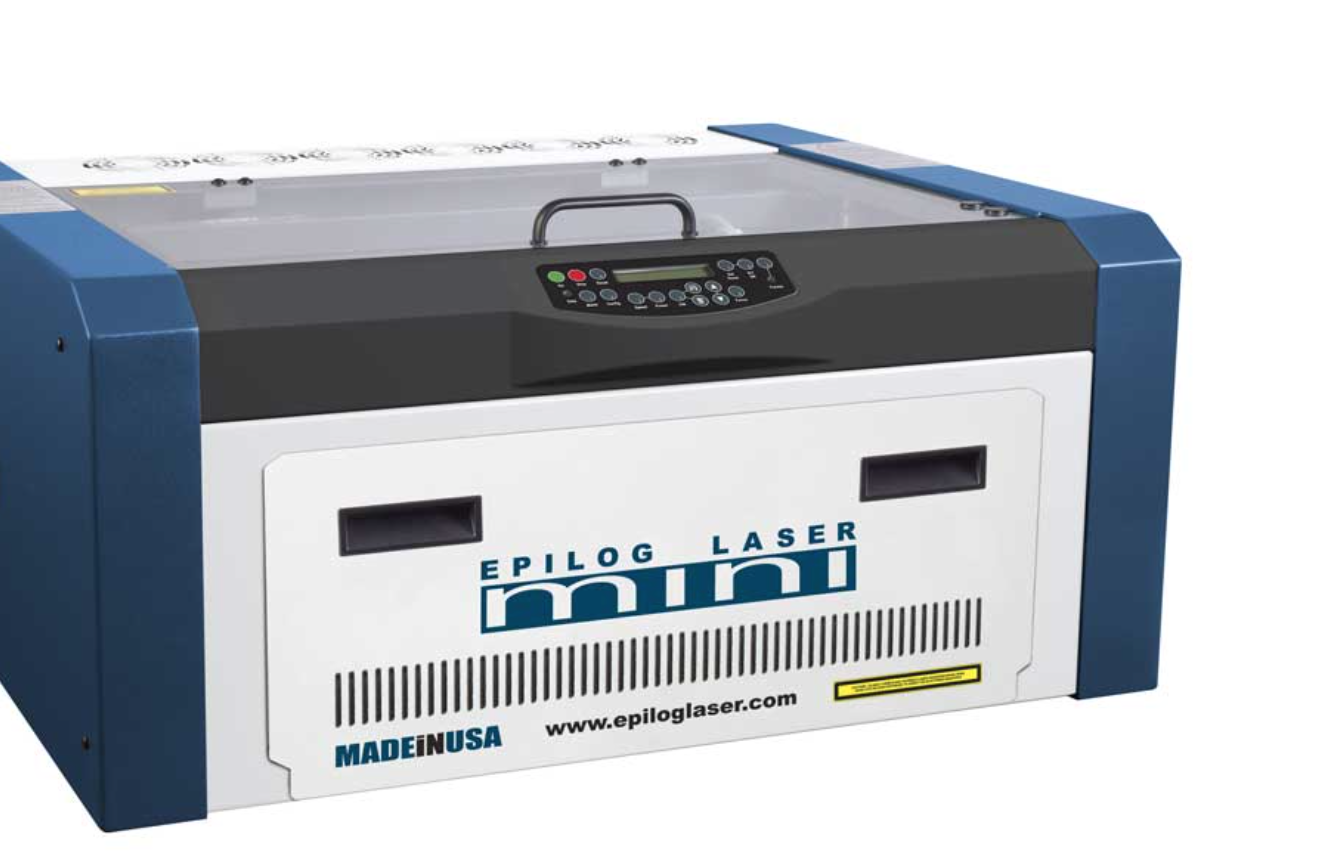
Our laser cutter is epilog 40 watt mini from epilog
SPECIFICATIONS
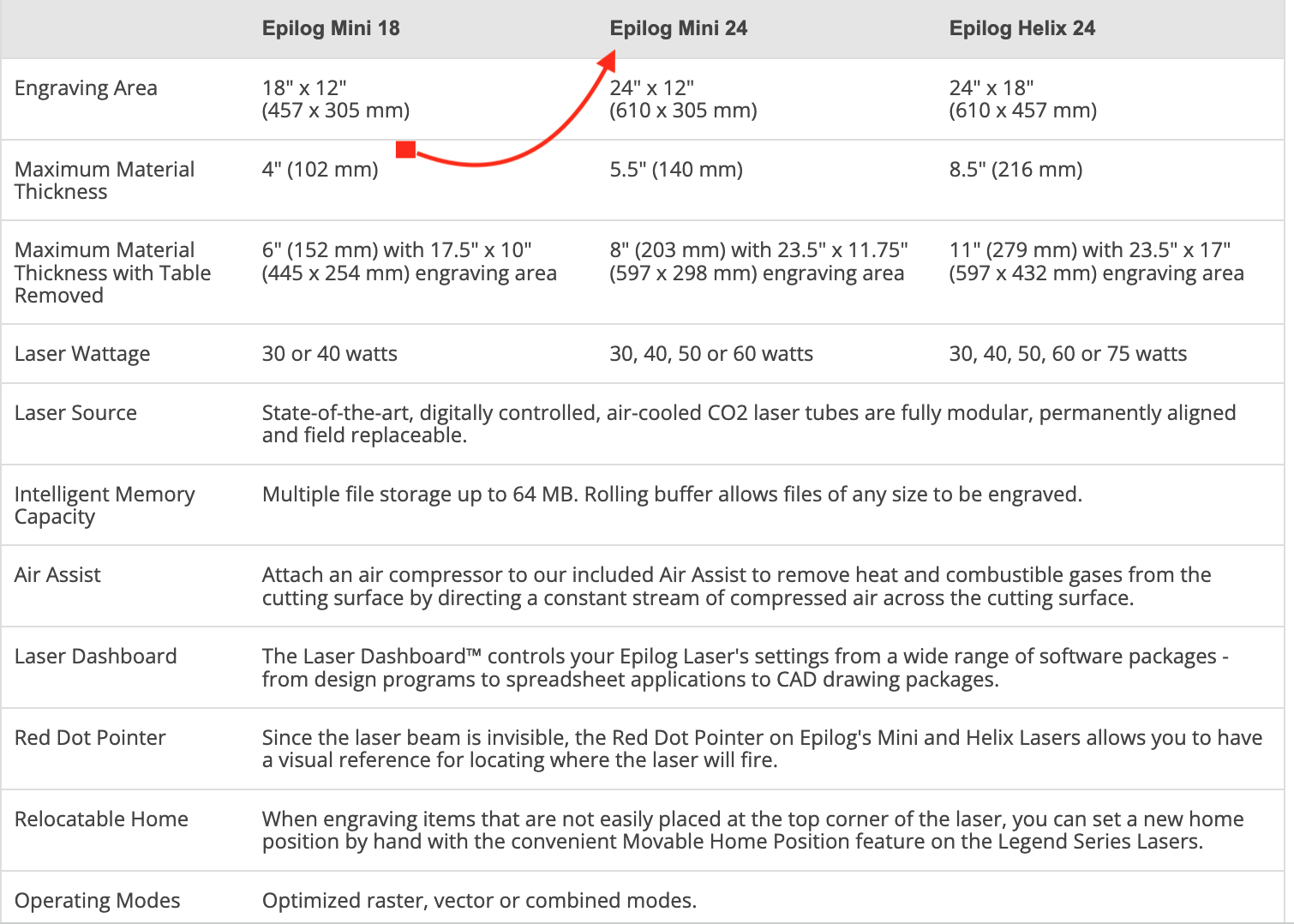
- Focus: The machine has a motorized table that can be adjusted to focus the laser beam on the material being cut or engraved. This allows for precise and accurate results.
- Power: The machine has a 40-watt laser tube that can cut and engrave a wide range of materials, including wood, acrylic, leather, paper, and more.
- Speed: The machine has a maximum engraving speed of 100 inches per second and a maximum cutting speed of 30 inches per second. This allows for fast and efficient production.
- Rate: The machine has a high-quality laser beam that can produce detailed and intricate designs with high resolution and accuracy.
- Width: The machine can cut or engrave materials up to 16 inches wide and 12 inches deep.
- The machine has a precision bearing system that ensures accurate positioning and smooth movement of the laser head, resulting in clean and precise cuts and engravings.
- Types: The machine is capable of cutting and engraving a wide range of materials, including wood, acrylic, leather, paper, glass, and more. It can also produce 3D engravings and perform rotary engraving with an optional rotary attachment.
Individual Assignment : Designing a parametric press kit
1. What is Parametric design ?
As a beginner in design , i was not aware in about parametric design and i have to make reserach online so that i understand the concept.
According to Wikipedia a parametric design is defined as a type of design process in which the relationships between various design elements are defined using parameters or variables. By changing the values of these parameters, the design can be easily modified and adjusted to meet different requirements or constraints. This allows for greater flexibility, efficiency, and precision in the design process.
Because i alredy started using solidworks , i knew through this link that solidworks can do parametric design
2. Parametric press-fit construction kit
what i made: customizable stacking boxes
This i a just a customizable stacking boxes that can be used by babies when they are playing with joining different parameters my idea is to print them on MDF of 2.46mm which are available in our fablab .
Before i knew what parametric press-kit means, i did some research then i come out with a definition of press-fit . According to this Resources the parametric press kit can be defined in the following way:
A parametric press-fit is a method of joining two parts together by means of a tight, interference fit. In this technique, the size and shape of the mating features of the two parts are designed in a way that allows them to be pressed together with a controlled amount of force, creating a secure and permanent bond between them
In a parametric press-fit, the dimensions of the parts are carefully calculated to ensure that the press-fit joint is strong enough to hold the parts together, but not so tight that the parts are damaged during assembly. The press-fit joint relies on the elasticity of the materials and the tightness of the fit to create a secure connection.
And i found that This technique is commonly used in manufacturing, particularly in the production of electronic components and assemblies, where a reliable and strong mechanical connection is required.
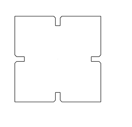
The original design i wanted to cut is the following
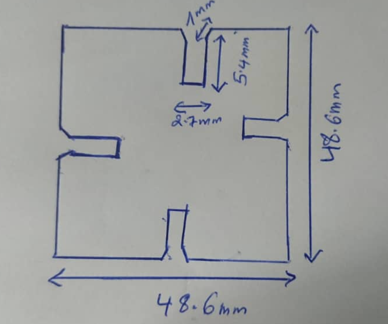
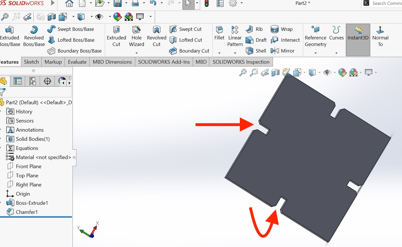
The next steps i to design that shape in solidworks
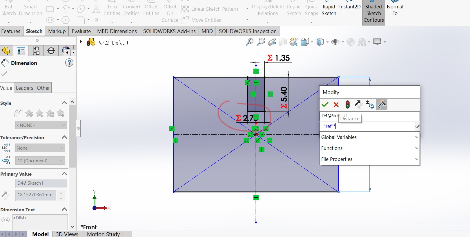
I have created circular rectangle in the centre line
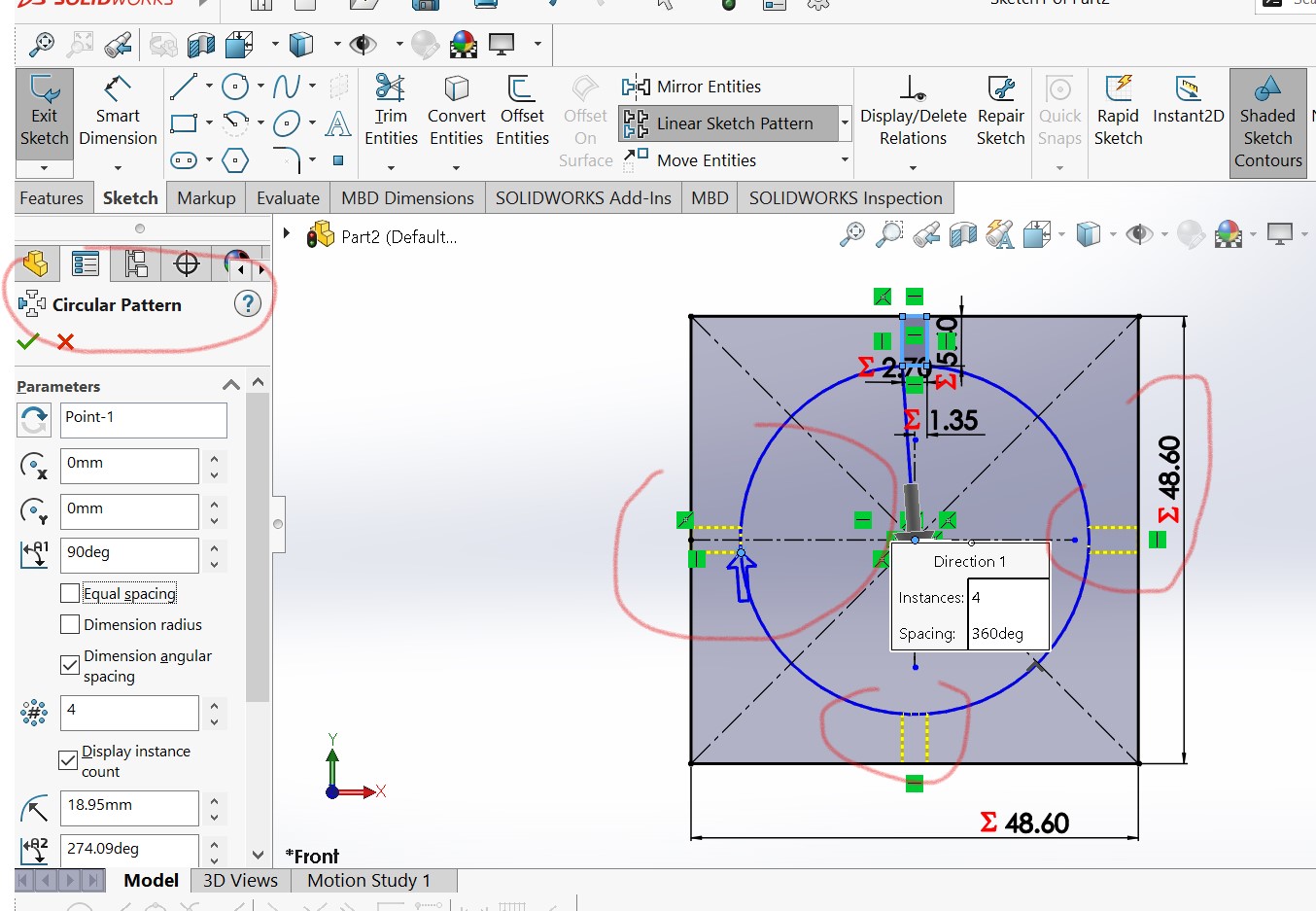
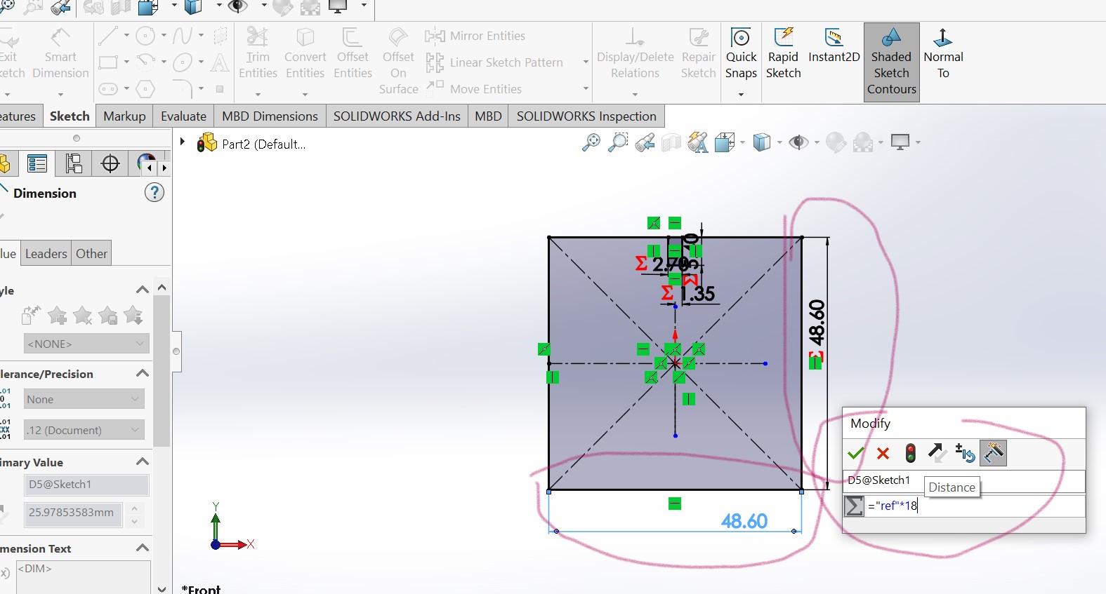
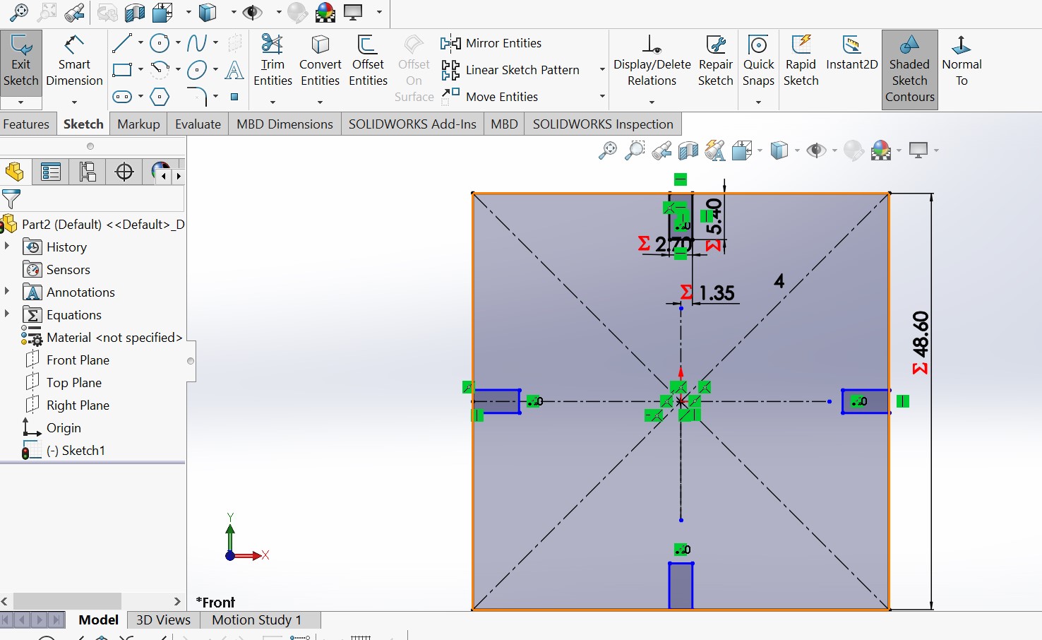
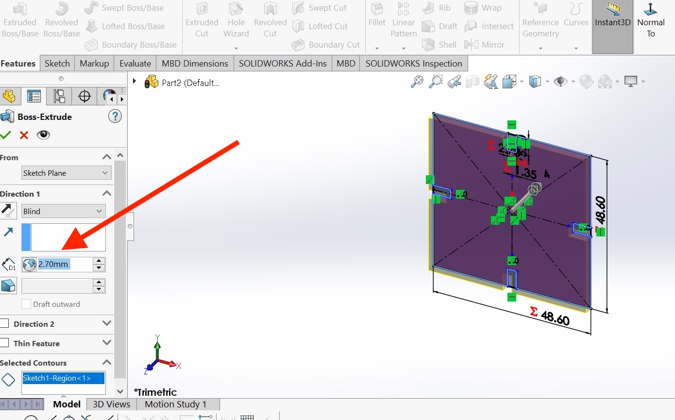
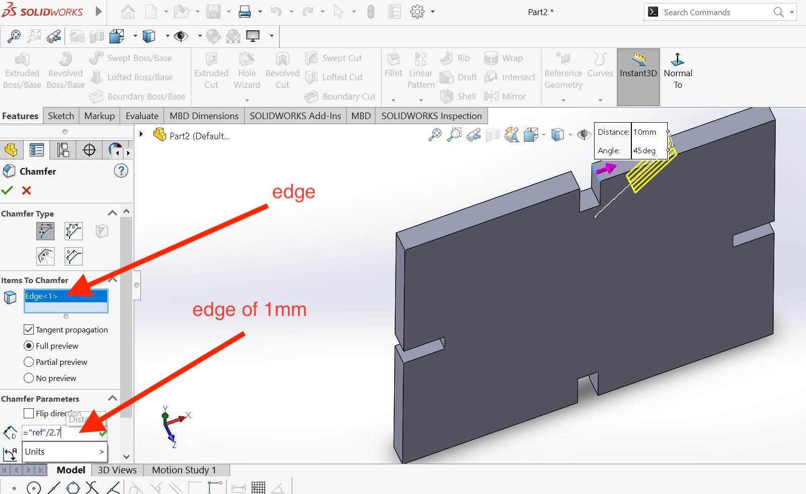
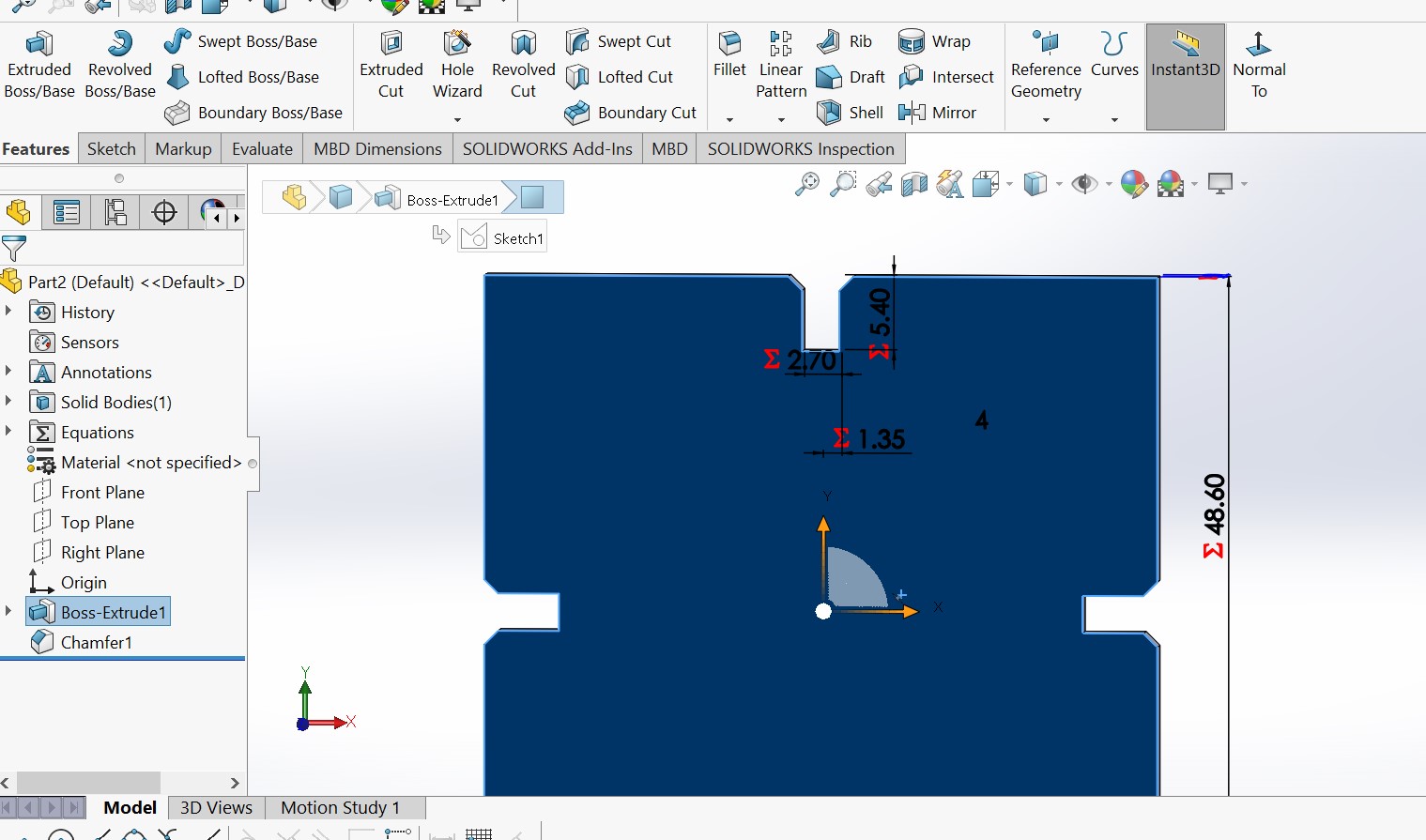
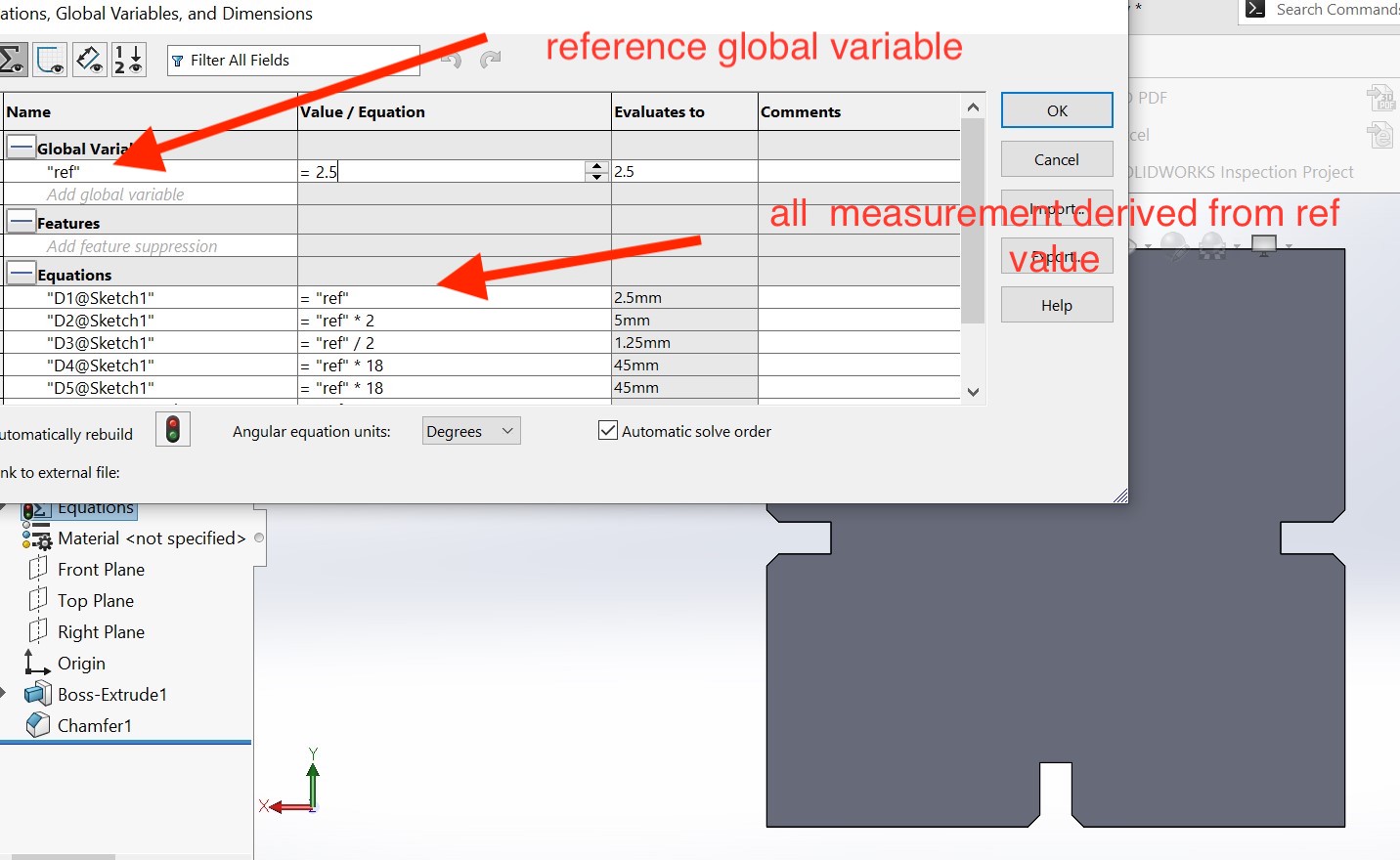
i have used ref value to be a reference of all meaurement of my design . there is no hardcoded value. if ref is changed, all dimension are changed in order to keep the same shape.
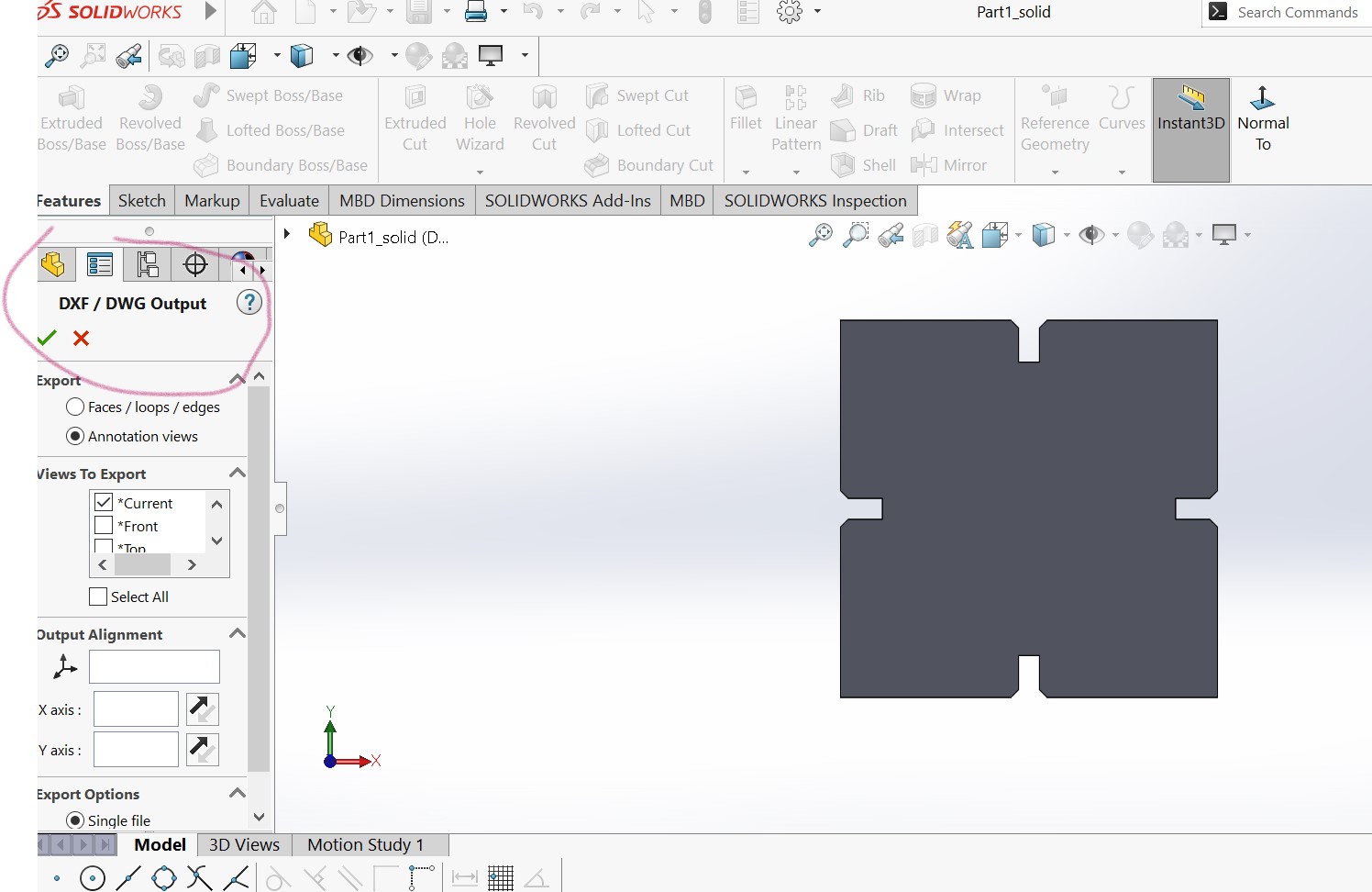
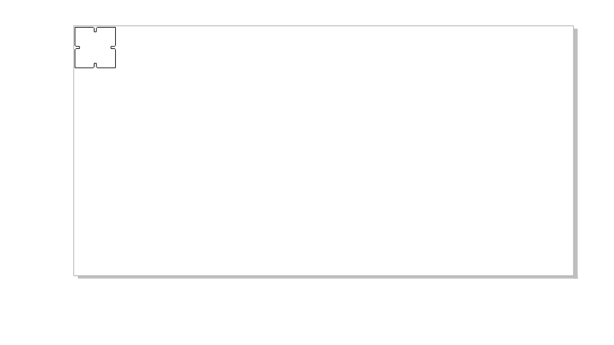
The final design is saved in dxf format to be recognized in coredraw to be prepared for vector creation
3 .Preparing DXF image in Coredraw before Cutting
in order to make vectors to be followed by laser cutter while cutting , we have to use coredraw. but there is other software that can be used like inkscape. as we have a desktop computer connected to our epilog laser cutter with coredraw installed , i used it to create vectors
why coredraw prefered? CorelDRAW is often used for laser cutting because it is a powerful and versatile vector graphics software that can create highly detailed and precise designs. Laser cutters use a high-powered laser to cut and engrave various materials, including wood, acrylic, and metal.
DXF is a file format used for exchanging CAD (Computer-Aided Design) data between software programs. The DXF file format is developed by Autodesk and stands for Drawing eXchange Format. It is a vector image format used to represent 2D and 3D designs and models.
DXF files can contain various types of data, including geometric shapes, text, and colors, as well as information about layers, line styles, and other properties. DXF files can be opened and edited by many CAD software programs, including AutoCAD, SolidWorks, and CorelCAD, among others.
First i have to copy and paste the image in coredraw interface
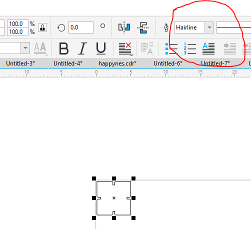
Using Hairline in coreDraw. why?
According to coreDraw community Using hairlines in CorelDRAW can be useful for creating very fine and precise lines, especially when designing for print or engraving. A hairline is a line with a width of 0.003 mm (or 0.0001 inch), which is the smallest possible line width that can be printed or engraved.
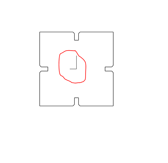
The problem i faced is finding the unwanted lines in the shape. i used coredrawto remove it because i dont want the lase cutter to cut it .
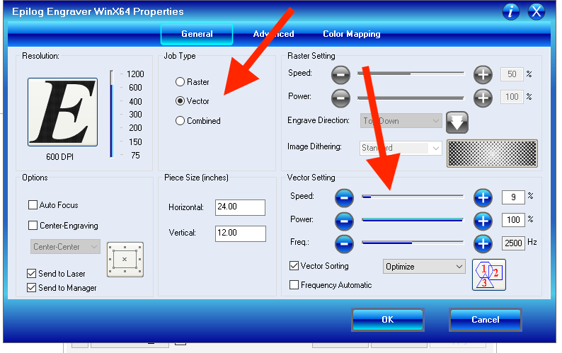
To send the vector file to laser cutter , we hace to select the appropriate laser cuttter and then set some properties
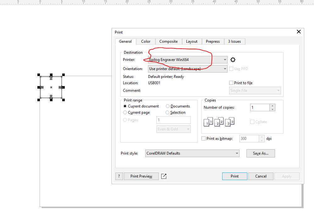
Then we have to modify some parameters like power, speed and job type(raster,vector or both). we hve selected vector because it is a vector image
After this we send teh job in the laser to cut the pieces we want
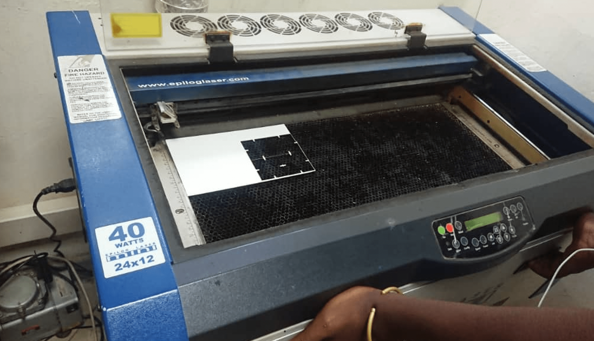
LaserCut with Laser Cutter
This is our epolog laser cutter 40 watt mini. it has a bed size of 24x12mm
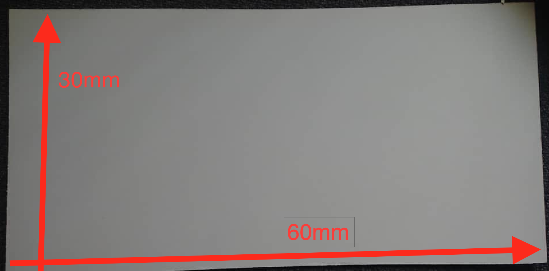
We have tried many kirf sizes and finally we selected 2mm , it was convenient to have pieces tight enough
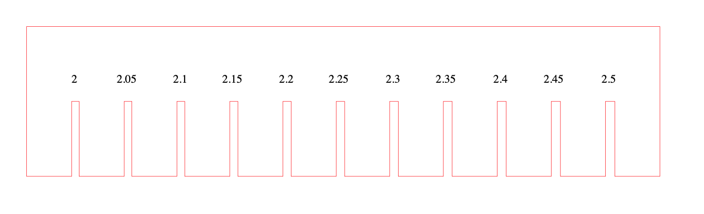
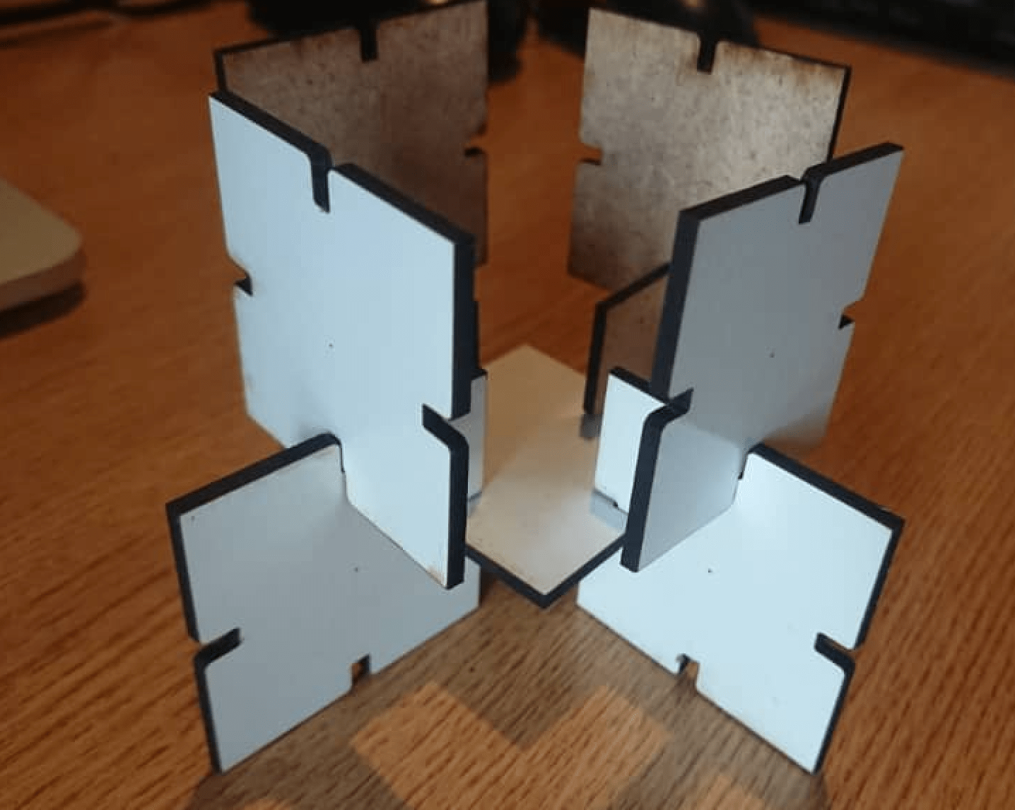
The width of 2.7mm was a bit high and the pieces was not fiiting well. i have tryied 2.5mm but aso it was not fitting as required
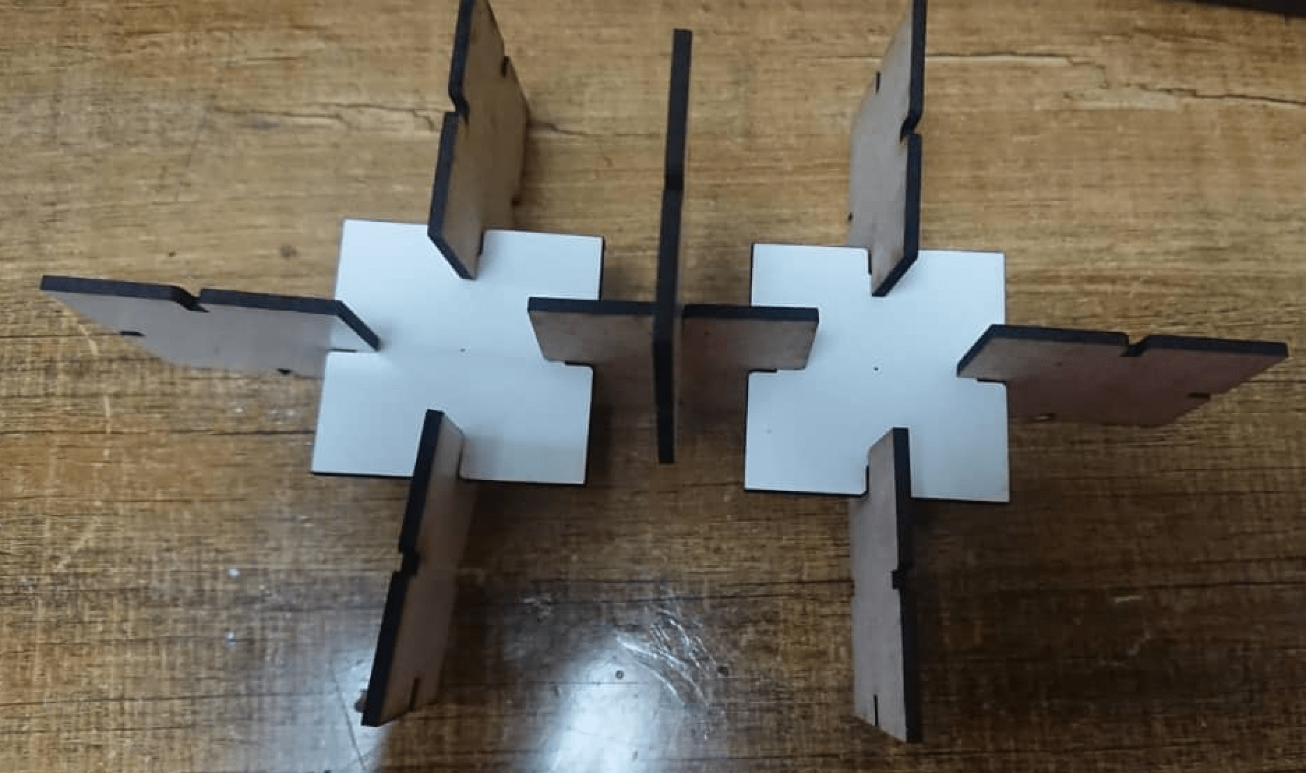
We tried many kirf dimensions but finally we have seen that using 2mm is enough to have pieces fit togather tightly
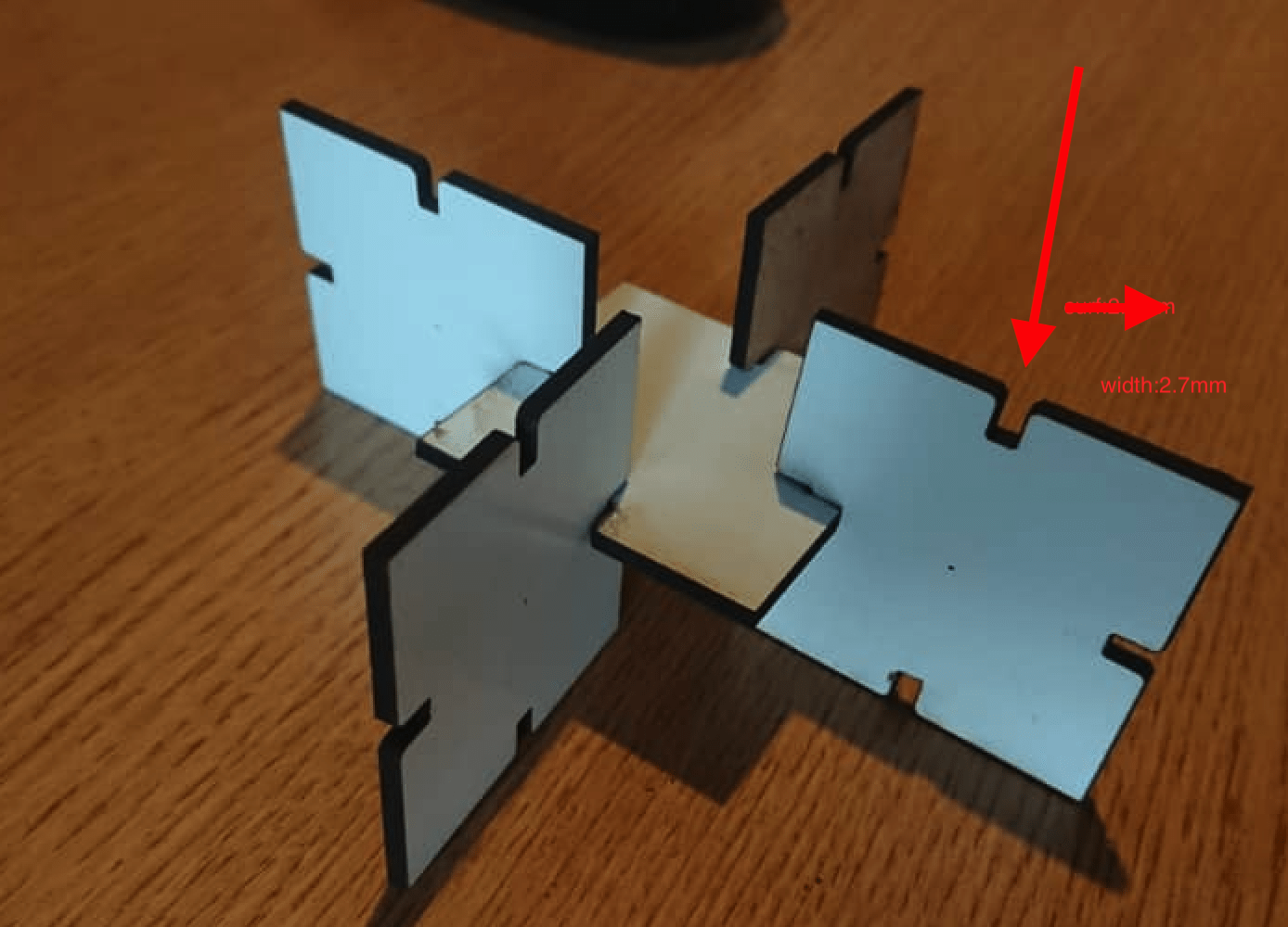
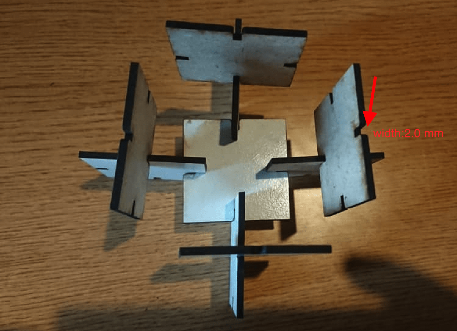
Finally i tryied the width of 2.0 mm and now the pieces were fit and tight . the pieces shown below are made with the width of 2mm
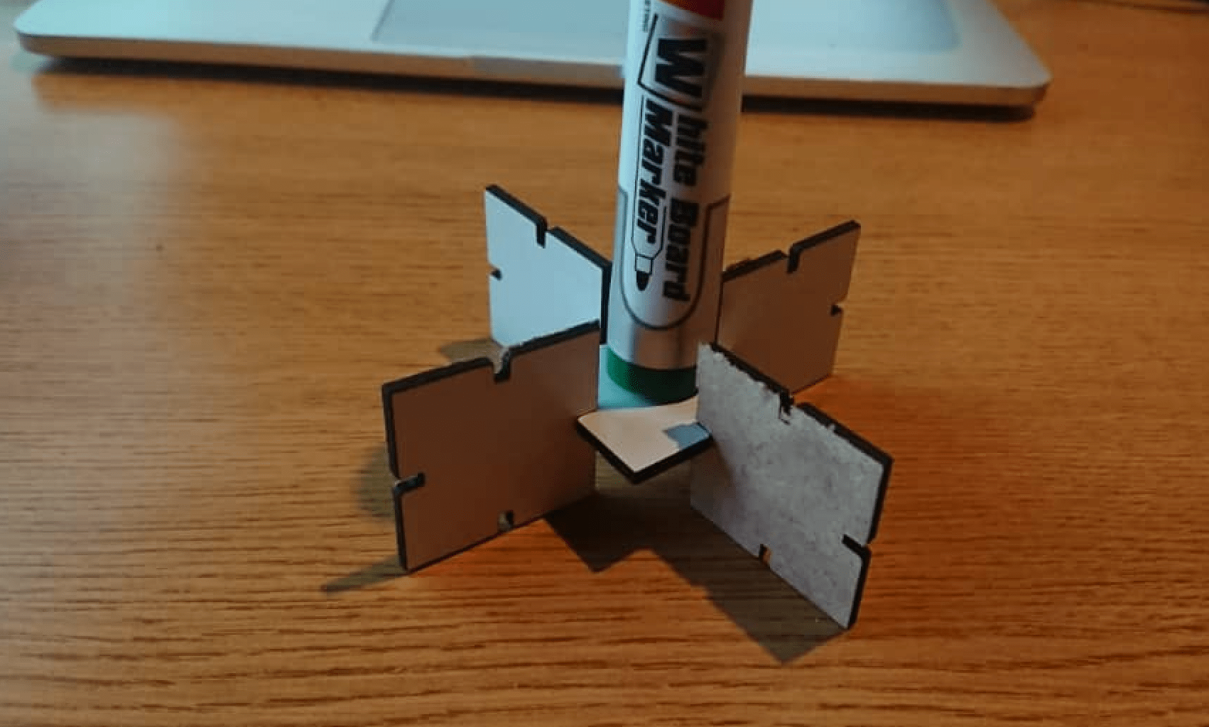
The printing process required many try and fail in order to have pieces that can be joined . that leads me to the skills of laser cutter manipulation and setting on coredraw software.
Vinyl Cutting
The cutting techniques with vinyl cutter was the first experienced to me to do it but i have seen it before someone using it with coreDraw software but i was not aware of what was going on. The fab academy training was a change for me to get access to fablab rwanda in to have access on vinyl cutter .
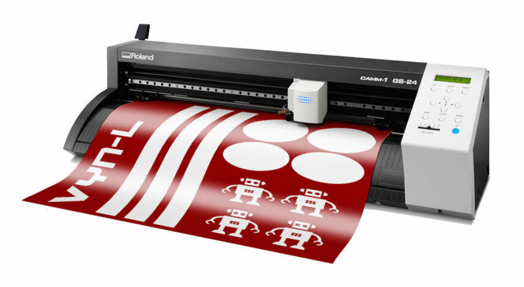
The vinylcutter available at fablab Rwanda is Roland DG CAMM-1 GS-24. the Roland DG CAMM-1 GS-24 desktop cutter is precision and efficiency to the max. With a completely redesigned cutting carriage and blade holder, the GS-24 offers great stability, up to 10x overlap cutting and down force of up to 350 grams so that you can cut like never before — even on thick, dense substrates. The GS-24 is Roland DG's best desktop cutter ever.
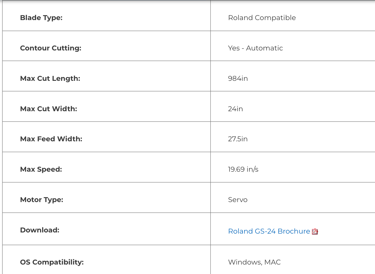
According Rolaand Offiial website , The machine has the following specification
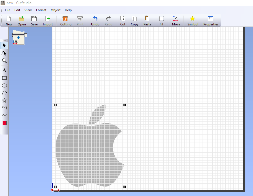
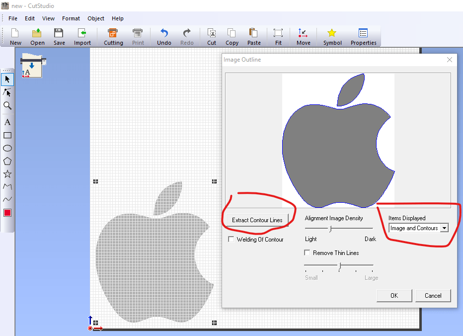
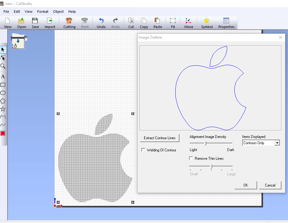
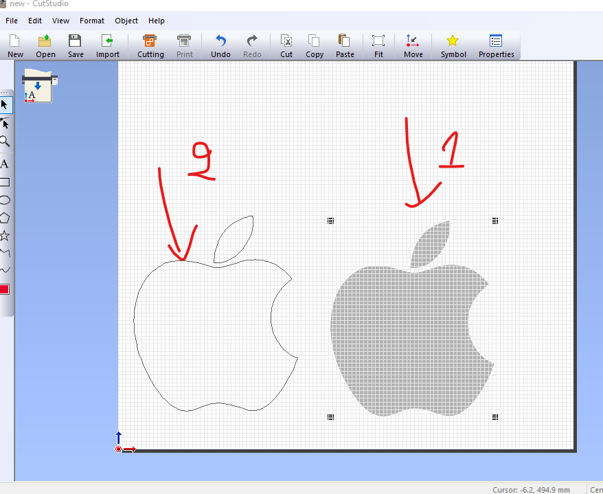
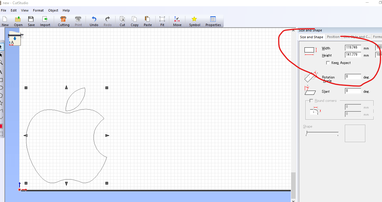
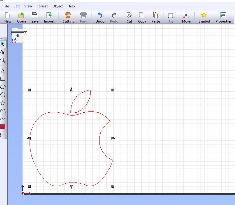
What i wanted to do is to cut the apple logo to put on backside of my MAC pc and i dowloaded the logo and prepare it to be cut by vinyl cutter
The first thing i have to do is to to select software compatible with the type of laser i have. i used the software called cutStudio which is a paid software. it is installed in fablab rwanda Desktop pc and it is what i have used
Setting vinyl cutter before cutting
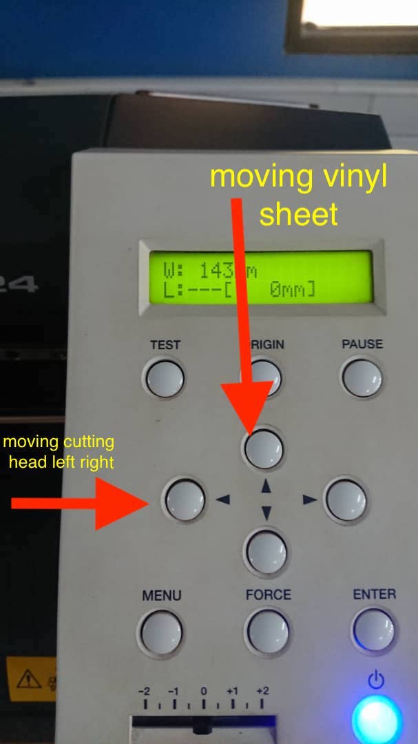
The first thing is to place the vinyl sheet in the vinyl cutter and position sensors in between the area where the cutter have to use . so do that you press enter button and the machine show you the size of selected length.
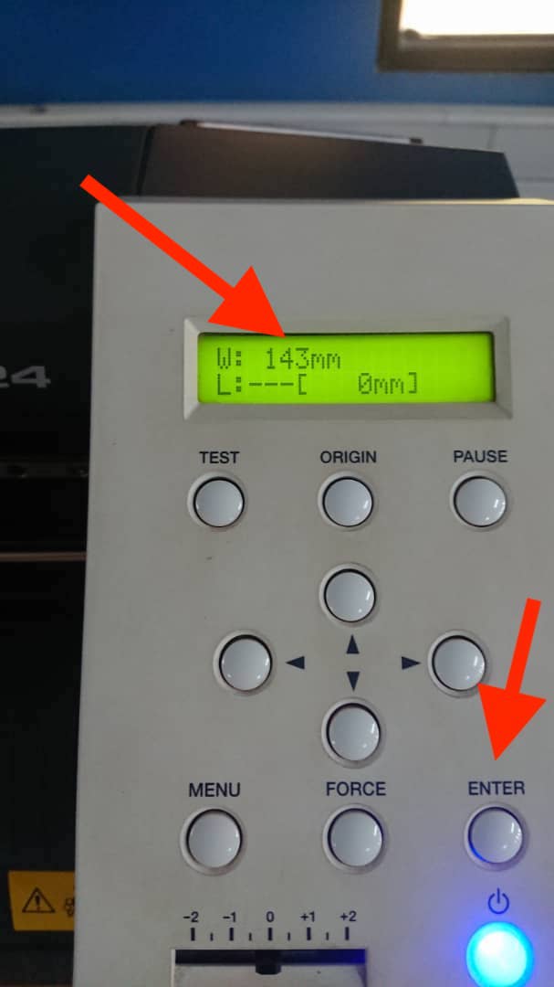
To move the vinyl sheet front and back and cutting head left and right we use the arrow keys as indicated in the image below
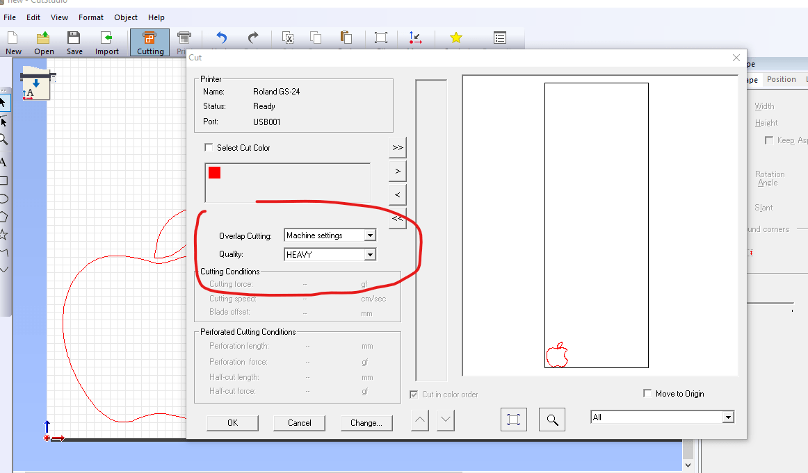
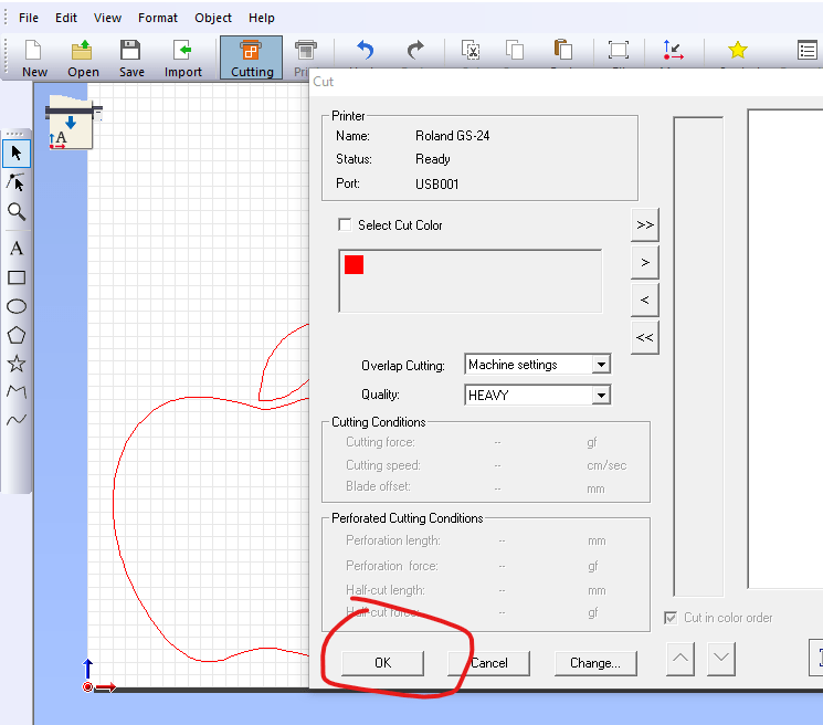
Then before printing , we have to set the reference or origin or your cutting. you just use arrow keys for cutting head positioning and then you press on origin button and then you get the message saying that the origin is set.

After setting origin , you can send the job to the vinyl cutter
Results
After cutting, i got a logo shape and i used it as a sticker on back of my mac pc
Cutting with Vinyl cutter in our fablab
Challenges Faced
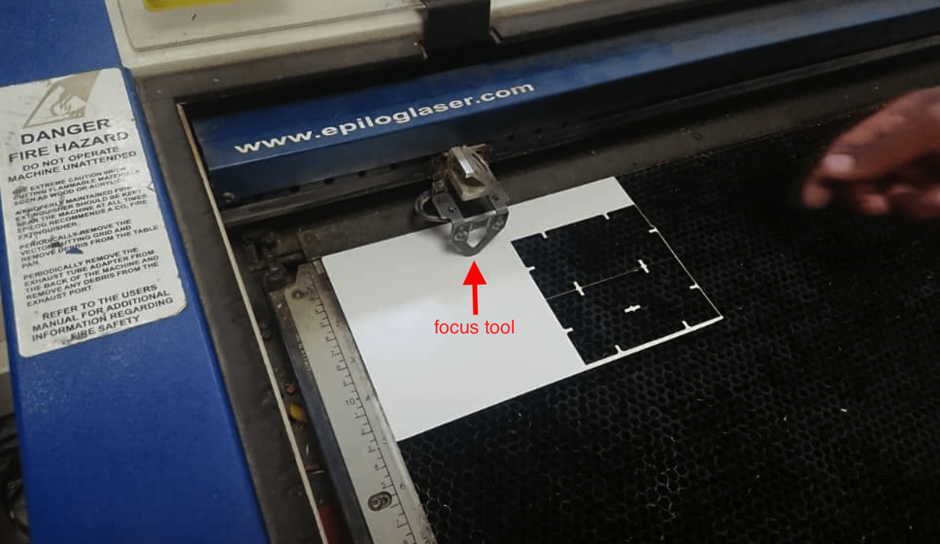
The first challenges i had is to convert dxf image in coreDraw because it was the first time using coredraw to prepare vectors needed to cut the pieces needed. another challenges was to set laser bed to position MDF sheet which is not having the full size of laser maximum bed size. setting focus was challenging but the instructor have helped us to set it in convenient way.