Week 4: Embedded programming
Group Assignment
- Compare the performance and development workflows for other architectures
- Document your work to the group work page and reflect on your individual page what you learned
Individual Assignment
- Browse through the datasheet for your microcontroller
- Program a microcontroller development board to interact and communicate
What i learned from the group assignment
The group assignment can be viewed here and i have learned a lot from what we dicovered about microcontroler archectures
There are several different MCU architectures available on the market, each with its own advantages and disadvantages in terms of development workflow and performance. The most common architectures include AVR, ARM, PIC, and MSP430.
AVR architecture, which is used in Atmel's AVR family of MCUs, is known for its simplicity and ease of use. It has a well-established development environment, with a robust set of tools and a large community of developers. The AVR architecture is particularly well-suited for low-power applications and real-time control systems, thanks to its efficient instruction set and low power consumption. However, it may not be as powerful as some of the other architectures available, and it may require additional hardware to implement some features.
ARM architecture is widely used in a variety of applications, from mobile phones to high-performance embedded systems. It offers a wide range of performance levels, from low-power microcontrollers to high-performance processors. The development workflow for ARM-based MCUs can be more complex than that of AVR MCUs, due to the wide range of options and configurations available. However, the extensive documentation and support available make it possible for developers to quickly become proficient with the technology. ARM-based MCUs are known for their high performance, advanced features, and scalability, making them ideal for applications that require high processing power, memory, and connectivity.
i can conlude that , the choice of MCU architecture depends on the specific requirements of the application. For applications that require simplicity, ease of use, and low power consumption, AVR architecture may be the best choice. For applications that require high performance, scalability, and advanced features, ARM architecture may be the best choice. Developers must carefully consider the trade-offs between performance, development complexity, and cost when selecting an MCU architecture for a given application.Microcontroller Datasheet SPECS
I am familiar with microcontroller programming especially AVR family. As arduino platform has gained popularity , i was attracted by the arduino prpframming style becuase large community , support and library availability. I have worked with differents microcontroller boards like arduino uno,Mega, Due , nano and pico. but the drawback of those microcontrillers is the lack of wireless communication protocols to be used in various IoT projects.
From that background, i hve shifted from arduino boards to other boards from the Expressif company which produce system on chips packages that are suitable for IoT Projects. one of the microcontroler baord from expressif i like is esp8266.
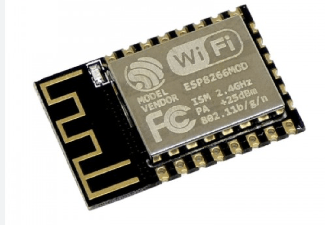
According to expressif company, ESP8266 is a low-cost, Wi-Fi enabled microcontroller and system-on-chip (SoC) that is widely used in the field of Internet of Things (IoT) and embedded systems. It was developed by the Chinese company Espressif Systems, and was first released in 2014
The ESP8266 includes a powerful 32-bit Tensilica processor, integrated Wi-Fi connectivity, and a range of input/output (I/O) pins that can be used for controlling external devices or sensors. It can be programmed using the Arduino IDE, as well as other programming languages such as MicroPython and Lua.
The ESP8266 is widely used in a variety of IoT applications, including home automation, remote sensing, and wireless communication. Its low cost and ease of use have made it a popular choice among hobbyists, makers, and professional developers alike.
ESP8266 Datasheet and Technical Specifications
| Specification | Value |
|---|---|
| Name of MCU | ESP8266 |
| Architecture | Tensilica LX106 |
| Clock Speed | 80 MHz |
| Memory |
|
| Number of Pins | 32 |
| GPIO Pins | 17 |
| Digital Pins | 11 (GPIO0-GPIO10) |
| Analog Pins | 1 (A0) |
| Pins capable of PWM | 6 (GPIO0-GPIO5) |
| Communication Protocols |
|
| Hardware Peripherals |
|
Original datasheet can be downloaded here
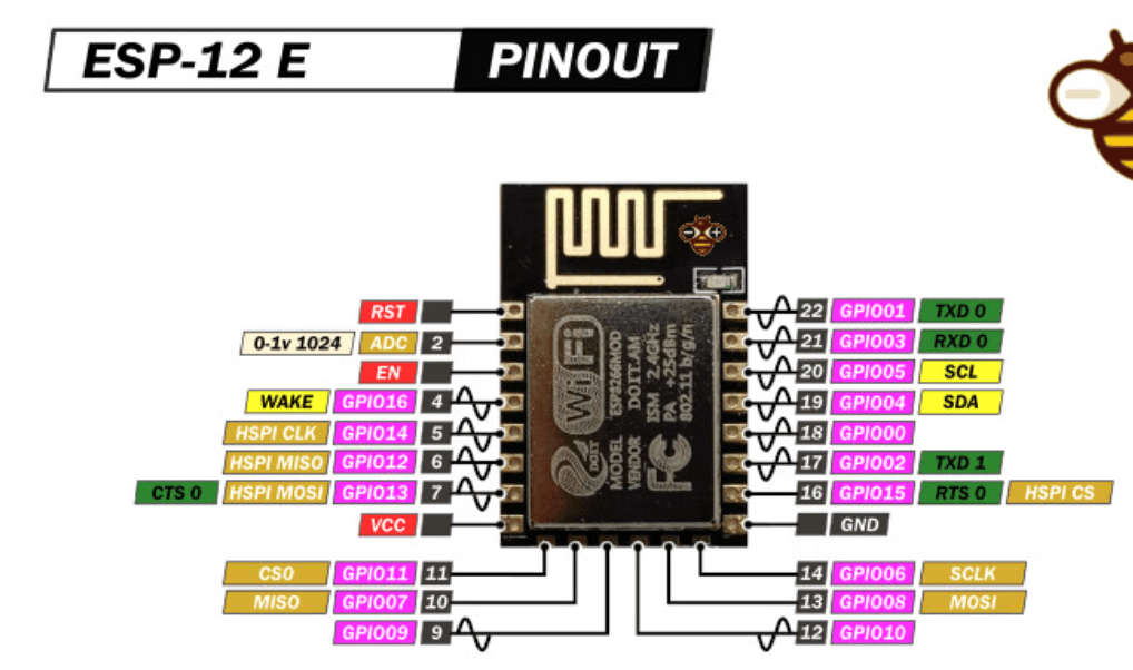
ESP-12E
In this week 4 Assignment, i prefer to use one of the variaties of esp8266 which called esp-12E built within the dev board called nodemcu V3
When i refer to This online resource,The ESP-12E is similar to other ESP8266 variants in that it includes a powerful 32-bit Tensilica processor, integrated Wi-Fi connectivity, and a range of input/output (I/O) pins that can be used for controlling external devices or sensors. However, it also includes some additional features that are not found in other ESP8266 modules, such as more memory and an external antenna connector.
Specifically, the ESP-12E includes 4MB of Flash memory and 32KB of SRAM, which is more than some other ESP8266 modules. It also includes an external antenna connector, which can be used to improve the range and stability of the Wi-Fi connection. Additionally, the ESP-12E has a slightly different pinout than other ESP8266 modules, which may affect how it is used in certain projects.
ESP-12E is a member of the "ESP-XX" series. It is a miniature Wi-Fi module used to establish a wireless network connection for a microcontroller or processor. The core of ESP-12E is ESP8266EX. This module has no complicated circuits or programming so using this module is very easy. The ESP-12F module is also a member of the "ESP-XX" series which combines the ESP8266 microcontroller with 4MB of flash and a PCB antenna. The ESP-12F is an improved version of the 12E. It is pin compatible with enhanced stability and a better antenna.
They several development boards built with esp8266. the following table provides an overview of 5 among dev boards available on market
Top 5 ESP8266 Development Boards
| Name of Dev Board | Processor | Flash Memory | GPIO Pins | Other Features |
|---|---|---|---|---|
| NodeMCU | ESP-12E | 4 MB | 17 | USB, CP2102 Serial Converter |
| Wemos D1 Mini | ESP-12F | 4 MB | 11 | Micro USB, 1-Button Reset, SMD Antenna |
| Adafruit Huzzah ESP8266 | ESP-12F | 4 MB | 9 | Micro USB, LiPo Battery Connector, CP2104 Serial Converter |
| SparkFun ESP8266 Thing | ESP-12F | 4 MB | 11 | Micro USB, FTDI Serial Converter, Built-in Antenna |
| LOLIN/Wemos D1 R2 & mini | ESP-12F | 4 MB | 11 | Micro USB, CH340G Serial Converter, Built-in Antenna |
As i have said , i have to use nodemcu V3 in this week 4 assignment and it is demonstrated here in the following image

Micrpcontrollers Comparison between ESP8266 AND ESP32-WROM
here i wanted to compare both esp8266 and esp32-wrom in terms of performance and use
| Feature | ESP8266 | ESP32-WROOM |
|---|---|---|
| CPU | 80 MHz Tensilica L106 | Dual-core 240 MHz Xtensa LX6 |
| Memory | Up to 4 MB | Up to 4 MB Flash + 520 KB SRAM |
| WiFi | 802.11 b/g/n | 802.11 b/g/n/d/e/i/k/r/w |
| Bluetooth | No | Bluetooth 4.2 BR/EDR and BLE |
| GPIO | Up to 17 | Up to 36 |
| Analog Inputs | 1 (10-bit ADC) | 18 (12-bit ADC) |
| Digital Interfaces | I2C, SPI, UART | I2C, SPI, UART, CAN, Ethernet, SDIO |
| Operating Voltage | 3.3V | 3.3V |
| Price | Less expensive | More expensive |
Programming a microcontroller development Board
As i have said , was not new in Arduino programming and the Nodemcu v3 dev board is programmed with arduino IDE . THE language i use is C++
You start by downloading Arduino IDE and then you install the IDE . The installation process is indicated here
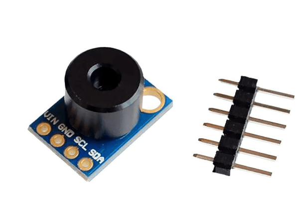
Selected Exercise: Infrared Thermomometer with MLX90614 Sensor and OLED Display
is an infrared thermometer sensor that can be used to measure the temperature of an object without physically touching it. It works by detecting the infrared radiation emitted by an object and converting it into a temperature reading. The sensor can measure temperatures in a range of -70 to +380 degrees Celsius with an accuracy of ±0.5 degrees Celsius.
The MLX90614 contains two thermopile sensors that detect the infrared radiation, one of which is sensitive to the ambient temperature and the other to the object temperature. The sensor uses an internal circuit to compensate for the ambient temperature and calculate the object temperature based on the difference between the two thermopile sensors. The MLX90614 is commonly used in various applications such as industrial temperature control, medical temperature measurement, and home automation systems. It can be easily interfaced with microcontrollers such as Arduino or NodeMCU to enable temperature measurement and control in various projects.
Required Components
- NodeMCU v3 board
- MLX90614 infrared thermometer sensor as Input Device
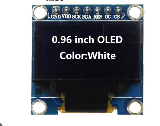
- 96 inch Oled Display as Output Device
- Breadboard and jumper wires
- USB cable to connect the NodeMCU board to a computer
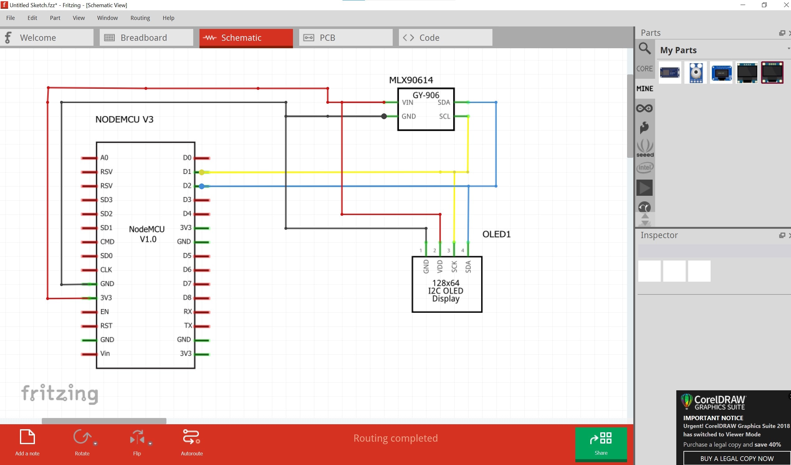
Wiring
- Connect the VCC pin of the MLX90614 to the 3V3 pin of the NodeMCU board
- Connect the GND pin of the MLX90614 to the GND pin of the NodeMCU board
- Connect the SDA pin of the MLX90614 to the D2 pin of the NodeMCU board
- Connect the SCL pin of the MLX90614 to the D1 pin of the NodeMCU board
- Connect the SDA pin of the oled Display to the D2 pin of the NodeMCU board
- Connect the SCL pin of the Oled Display to the D1 pin of the NodeMCU board
Arduino Code
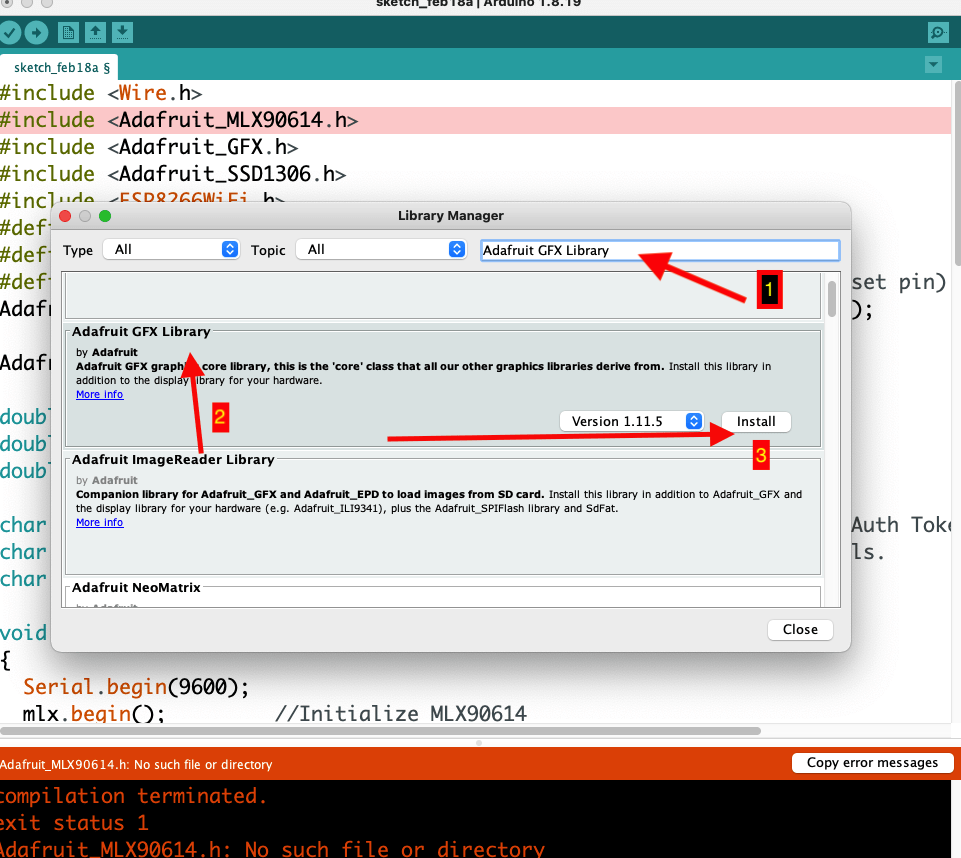
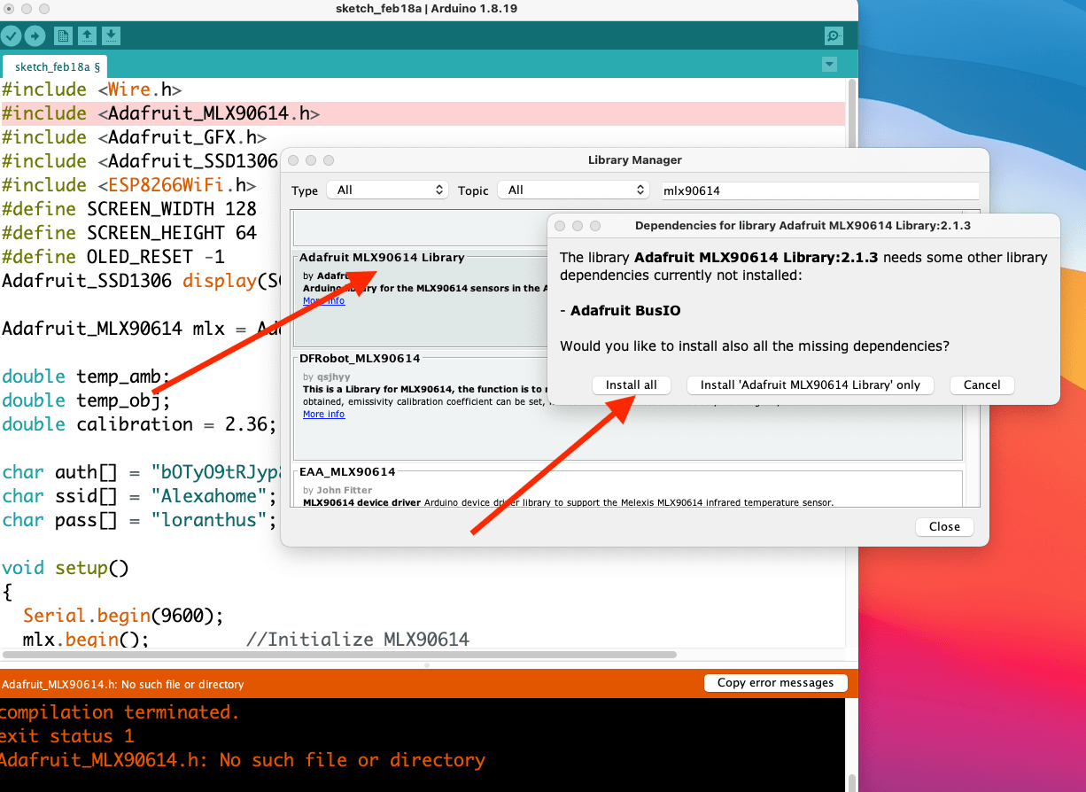
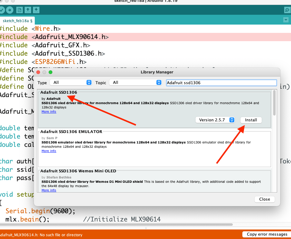
In order to use the nodemcu with MLX90614 AND OLED DISPLAY , We have to install some kind of libraries. One is Adafruit SSD1306 library for driving OLED display. other one is MLX90614 Library for reading the MLX90614 Sensor data and the last one is Adafruit GFX Library which is core graphics library for OLED Displays
libraries Installation process
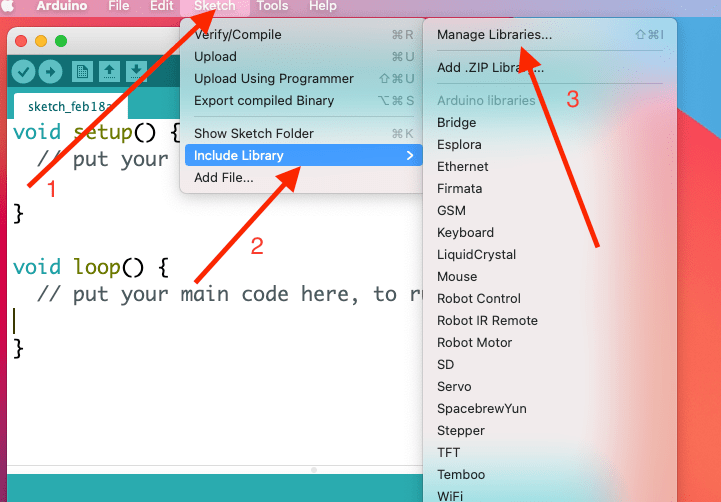
You have to open Arduino IDE, go to sketch menu>Include Library and click on library manager
You have also to install esp8266 board manager to have all baords based in esp8266 in your arduino IDE
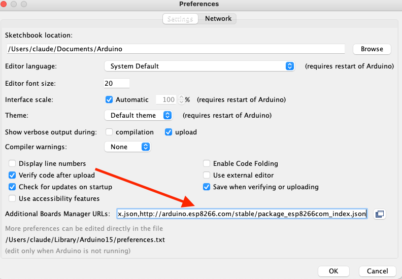
copy and paste this link in additional baords manager URLS under file>preferences .
https://dl.espressif.com/dl/package_esp32_index.json, http://arduino.esp8266.com/stable/package_esp8266com_index.json
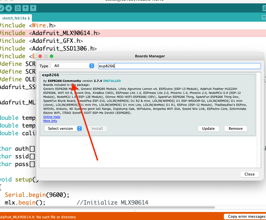
Downloading esp8266 boards. go to tools>BOARDS>BOARD MANAGER and write esp8266 in search filed and install it. on my case it is already installed
Write adafruit gfx IN SEARCH Field and install it.
Final code
            #include < Wire.h >
            #include < Adafruit_MLX90614.h >
            #include < Adafruit_GFX.h >
            #include < Adafruit_SSD1306.h >
            #define SCREEN_WIDTH 128    // OLED display width, in pixels
            #define SCREEN_HEIGHT 64    // OLED display height, in pixels
            #define OLED_RESET -1       // Reset pin # (or -1 if sharing Arduino reset pin)
            Adafruit_SSD1306 display(SCREEN_WIDTH, SCREEN_HEIGHT, &Wire, OLED_RESET);
            Adafruit_MLX90614 mlx = Adafruit_MLX90614();

            double temp_amb;
            double temp_obj;
            double calibration = 2.36;

            void setup()
            {
              Serial.begin(9600);
              mlx.begin();         //Initialize MLX90614
              display.begin(SSD1306_SWITCHCAPVCC, 0x3C); //initialize with the I2C addr 0x3C (128x64)

              Serial.println("Temperature Sensor MLX90614");

              display.clearDisplay();
              display.setCursor(25,15);
              display.setTextSize(1);
              display.setTextColor(WHITE);
              display.println(" Thermometer");
              display.setCursor(25,35);
              display.setTextSize(1);
              display.print("Initializing");
              display.display();
              delay(2500);
            }

            void loop()
            {
              //Reading room temperature and object temp
              //for reading Fahrenheit values, use
              //mlx.readAmbientTempF() , mlx.readObjectTempF() )

              temp_amb = mlx.readAmbientTempC();
              temp_obj = mlx.readObjectTempC();

              //Serial Monitor
              Serial.print("Room Temp = ");
              Serial.println(temp_amb);
              Serial.print("Object temp = ");
              Serial.println(temp_obj);

              display.clearDisplay();
              display.setCursor(25,0);
              display.setTextSize(1);
              display.setTextColor(WHITE);
              display.println(" Temperature");

              display.setCursor(10,20);
              display.setTextSize(1);
              display.print("Ambient: ");
              display.print(temp_amb);
              display.print((char)247);
              display.print("C");

              display.setCursor(10,40);
              display.setTextSize(1);
              display.print("Object: ");
              display.print(temp_obj + calibration);
              display.print((char)247);
              display.print("C");
              display.display();
              delay(1000);
            }
Code Explanation
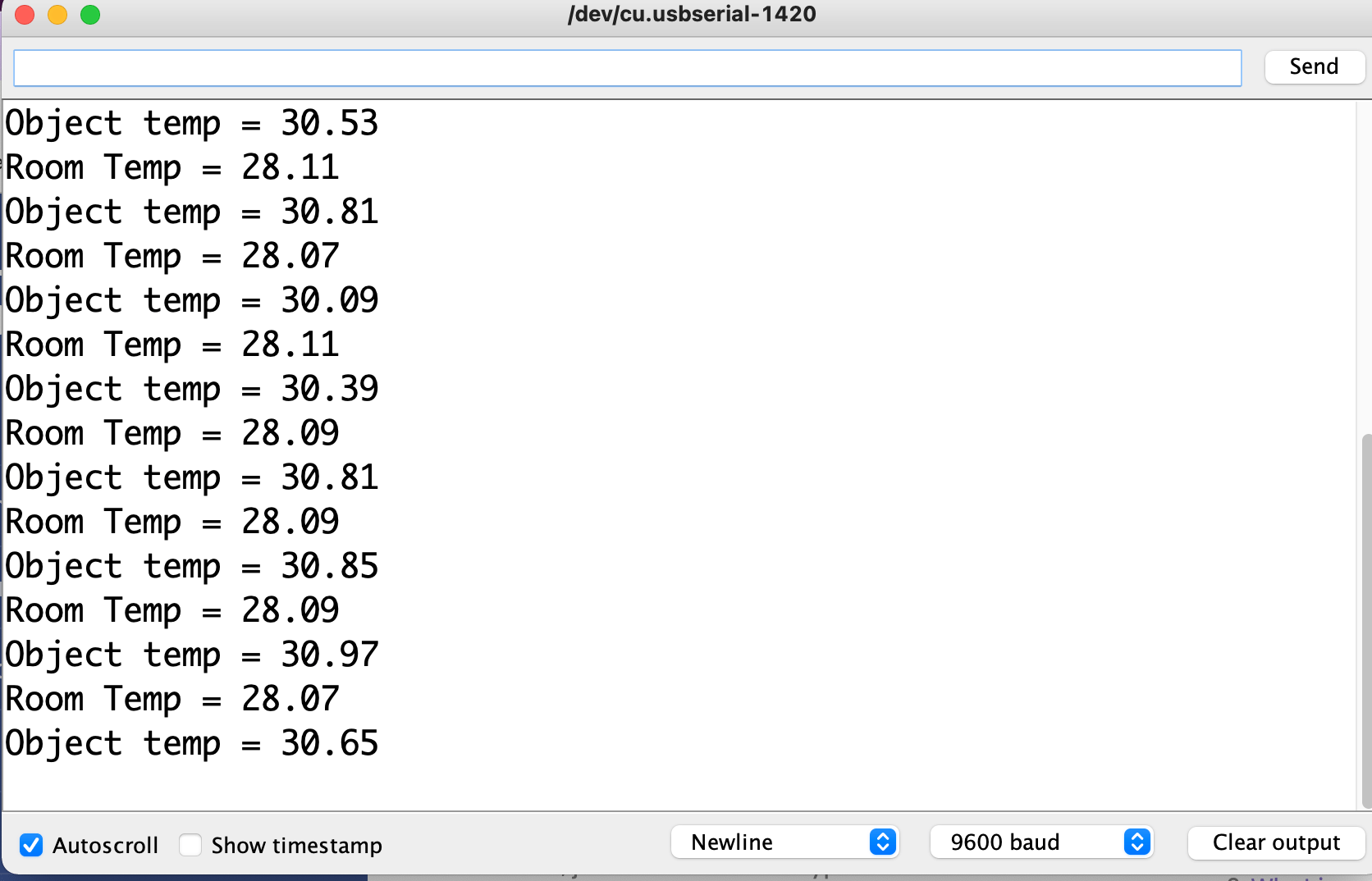
This is an Arduino program that reads temperature values from an MLX90614 infrared thermometer sensor and displays the values on an OLED screen and the serial monitor.
The program includes libraries for the MLX90614 sensor, the Adafruit SSD1306 OLED display, and the Adafruit graphics library. The program initializes the display and the sensor in the setup() function, and then in the loop() function, it reads the ambient temperature and the object temperature f rom the sensor and displays the values on the OLED screen and the serial monitor. The calibration variable is used to adjust the object temperature reading, and it is added to the temperature value before displaying it on the OLED screen.
The program uses I2C communication to interface the sensor and the OLED display with the NodeMCU board, and the Wire library is used for this purpose. The program defines the screen width and height, as well as the OLED reset pin. The display() function is used to update the OLED screen with the temperature values, and the delay() function is used to control the refresh rate of the screen.
Result on Serial Monitor
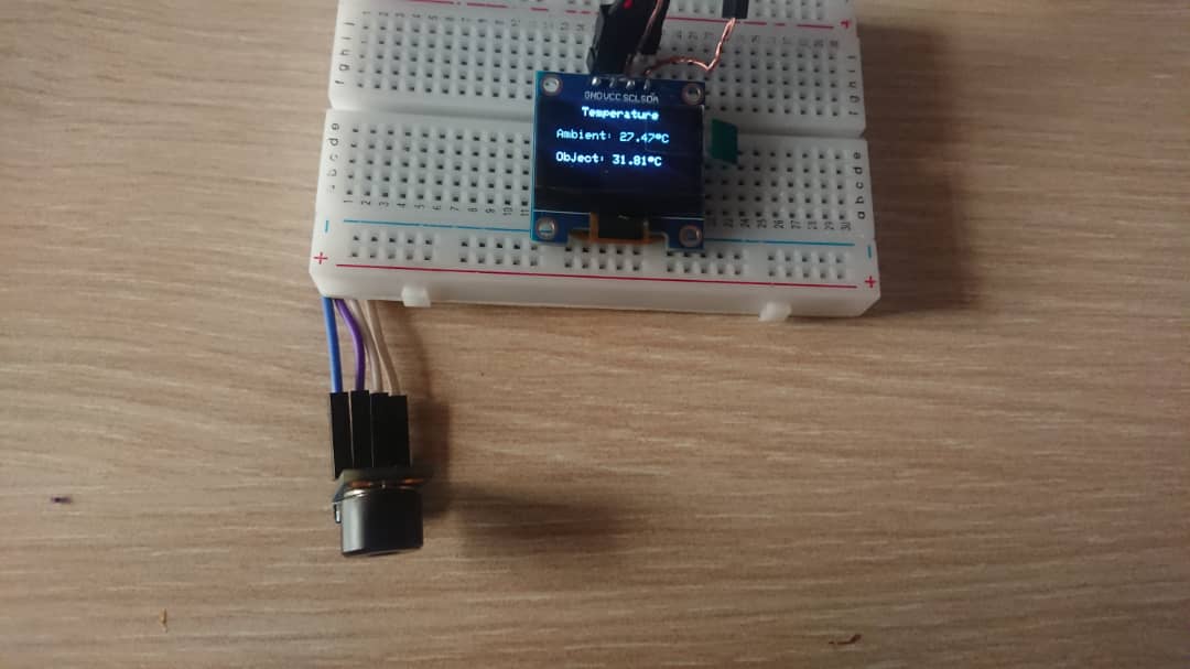
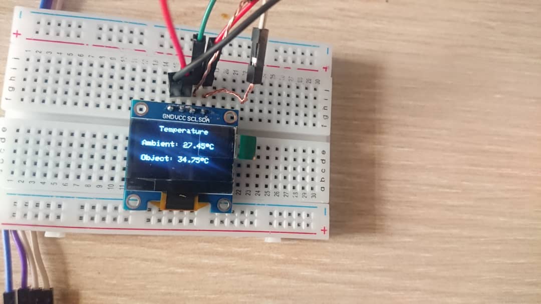
Final Output
ESP8266 Programming in Micropython
Micropython is a software implementation of the Python 3 programming language that is optimized to run on microcontrollers and other embedded systems. It was created by Damien George in 2013 as a way to bring the ease and simplicity of the Python programming language to devices with limited computing resources.
MicroPython allows developers to write Python code and run it directly on a microcontroller without needing an operating system or additional software. It includes a small subset of the Python standard library and is designed to be highly efficient and lightweight, using minimal resources such as RAM and storage. MicroPython supports a wide range of microcontrollers and development boards, including the popular ESP8266 and ESP32 , as well as the BBC micro:bit and many others. It also provides support for various sensors, actuators, and other hardware components commonly used in embedded systems.
To use micropython with nodemcu, i have used Mu pyhton editor you can download it here. you have to downlaod python 3 and above and configure environment in order to run python in command line and to be able to run micropython code
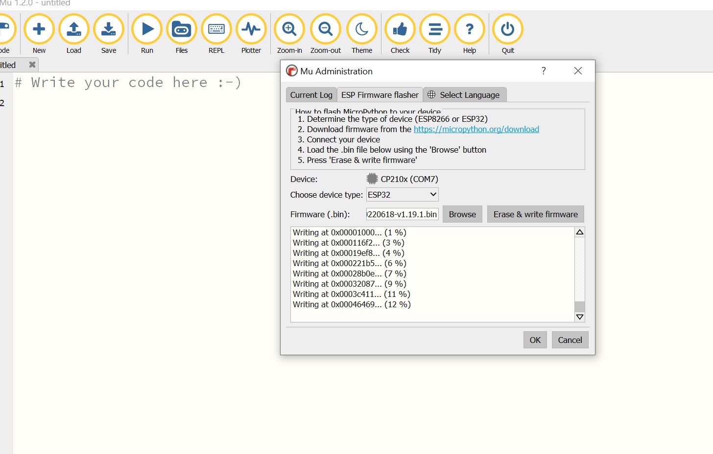
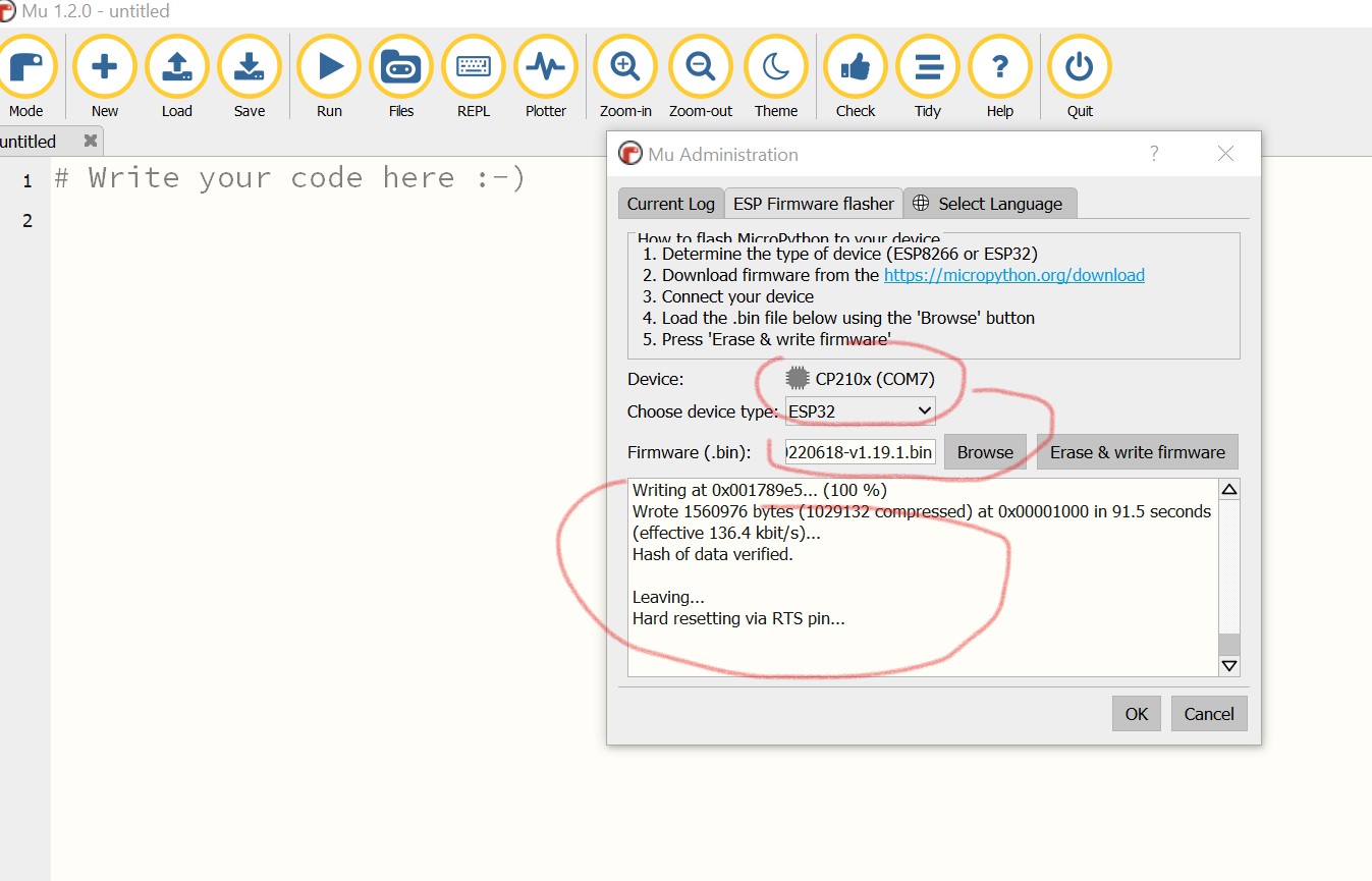
Installing Micropython firmware in nodemcu
By default, nodemcu are shipped with original firmware that runs arduino code . To use Micropython , i had to flash the nodemcu with new Micropython firmware . The firmware is Available here . I downloaded it and i saved it to local drive c. Mu IDE has the option to apload firmware in esp8266 and ESP32. Flashing nodemcu with Mu IDE procedures are shown here
After flashing the nodemcu, you just upload blink sketch and click run to run micropython code in nodemcu
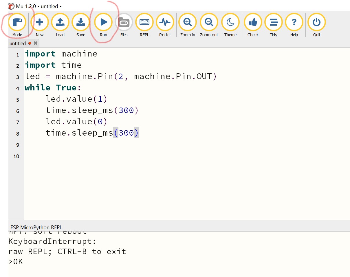
Blinking LED with micropython video
Adding a Comminication Protocol
The NodeMCU board has buit in wifi. so the baord is able to communicaye with another devices on IP networks.
The NodeMCU is a development board that is based on the ESP8266 Wi-Fi chip, which supports the IEEE 802.11 wireless communication protocol. The ESP8266 chip is capable of establishing Wi-Fi connections to other devices, such as routers, access points, and other ESP8266 boards, using standard Wi-Fi protocols like TCP/IP, UDP, HTTP, and HTTPS
It was quite easier for me to us wifi protocol over nodemcu because it was not the first time and i know all the process involved
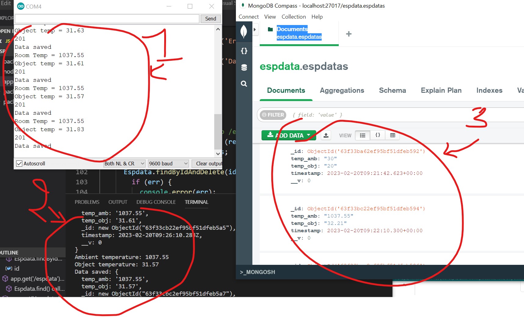
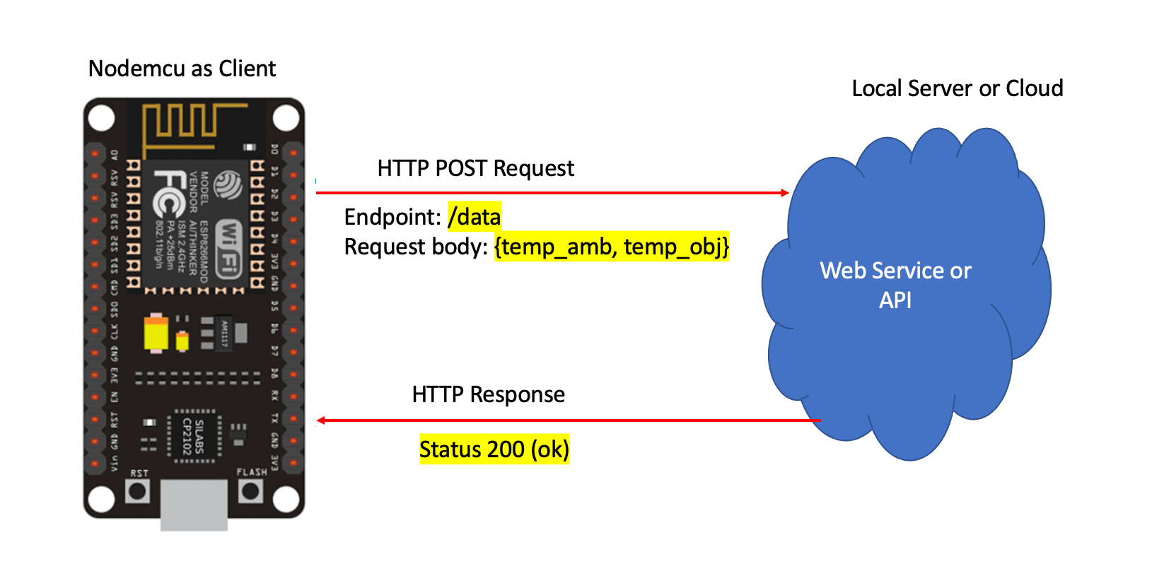
When asked to use one of the communication protocol on our assignment , I through about making a web server as backend that receives the temperature data from MLX90614 and save to local mongodb database. The nodemcu and local server should be connected to the same access point and the nodemcu will be connected on the wifi to route http traaffic to the server . the server also will have to reply to indicate the successful the packets reception.
Arduino code
            #include < Wire.h >
            #include < Adafruit_MLX90614.h >
            #include < Adafruit_GFX.h >
            #include < Adafruit_SSD1306.h >
            #include < ESP8266WiFi.h >

            #define SCREEN_WIDTH 128    // OLED display width, in pixels
            #define SCREEN_HEIGHT 64    // OLED display height, in pixels
            #define OLED_RESET -1       // Reset pin # (or -1 if sharing Arduino reset pin)
            Adafruit_SSD1306 display(SCREEN_WIDTH, SCREEN_HEIGHT, &Wire, OLED_RESET);
            Adafruit_MLX90614 mlx = Adafruit_MLX90614();

            double temp_amb;
            double temp_obj;
            double calibration = 2.36;

            const char* ssid = "your_SSID";
            const char* password = "your_PASSWORD";
            const char* host = "your_HOSTNAME_OR_IP_ADDRESS";
            const int port = 80;

            void setup() {
              Serial.begin(9600);
              mlx.begin();
              display.begin(SSD1306_SWITCHCAPVCC, 0x3C);
              display.clearDisplay();
              display.setCursor(25, 15);
              display.setTextSize(1);
              display.setTextColor(WHITE);
              display.println("Thermometer");
              display.setCursor(25, 35);
              display.setTextSize(1);
              display.print("Initializing");
              display.display();
              delay(2500);
              WiFi.begin(ssid, password);
              while (WiFi.status() != WL_CONNECTED)
          {
            delay(500);
            Serial.println("Trying to connect to wifi....");
          }
          Serial.println("");
          Serial.println("WiFi connected");
            }

            void loop() {
              temp_amb = mlx.readAmbientTempC();
              temp_obj = mlx.readObjectTempC();

              Serial.print("Room Temp = ");
              Serial.println(temp_amb);
              Serial.print("Object temp = ");
              Serial.println(temp_obj);

              display.clearDisplay();
              display.setCursor(25, 0);
              display.setTextSize(1);
              display.setTextColor(WHITE);
              display.println(" Temperature");

              display.setCursor(10, 20);
              display.setTextSize(1);
              display.print("Ambient: ");
              display.print(temp_amb);
              display.print((char)247);
              display.print("C");

              display.setCursor(10, 40);
              display.setTextSize(1);
              display.print("Object: ");
              display.print(temp_obj + calibration);
              display.print((char)247);
              display.print("C");
              display.display();
               //sending data to server every 30 seconds
              if ((millis() % ( 30 * 1000)) == 0) {
                WiFiClient client;
                if (client.connect(host, port)) {
                  String data = "temp_amb=" + String(temp_amb) + "&temp_obj=" + String(temp_obj + calibration);
                  client.println("POST /data HTTP/1.1");
                  client.println("Host: " + String(host));
                  client.println("Content-Type: application/x-www-form-urlencoded");
                  client.println("Content-Length: " + String(data.length()));
                  client.println();
                  client.print(data);
                  while (client.connected() && !client.available());
                  while (client.available()) {
                    Serial.write(client.read());
                  }
                } else {
                  Serial.println("Connection failed");
                }
                delay(1000);
              }
            }
Code Explanation
The provided code snippet is an Arduino sketch for an ESP8266-based thermometer that displays the temperature readings from an MLX90614 infrared thermometer on a small OLED display and also sends the readings to a remote server through a POST HTTP request. The sketch includes the necessary libraries to use the MLX90614, OLED display, and WiFi module. The ambient and object temperature readings are obtained using the MLX90614 and are printed to the serial monitor, as well as displayed on the OLED screen. The sketch also sends the temperature readings to a remote server every three minutes using a POST HTTP request. In summary, the code sets up the necessary hardware and libraries, reads and displays temperature readings, and sends them to a remote server using an HTTP request.
The Backend Code to Reeive nodemcu Data
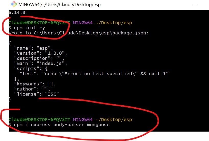
The backend is just an express based app . expressjs is nodejs framework to build web applications. You can downlod nodejs and expressjs here. mongodb can be downloaded here
Backend Code
Initiation of nodejs expess app
Final Code
const express = require('express');
const bodyparser = require("body-parser")
const mongoose = require('mongoose');
const app = express();
const port = process.env.PORT || 3000;
// connect to MongoDB
mongoose.connect('mongodb://localhost/espdata', {
useNewUrlParser: true,
useUnifiedTopology: true
});
// define espdata model
const espdataSchema = new mongoose.Schema({
timestamp: { type: Date, default: Date.now },
temp_amb: String,
temp_obj: String
});
const Espdata = mongoose.model('Espdata', espdataSchema);
// parse incoming requests with JSON payloads
app.use(bodyparser());
app.use(bodyparser.urlencoded({ extended: false }))
app.post('/data1',(req,res)=>{
console.log(req.body)
res.send("endpoint exist !!!!!!!!!!!!!")
})
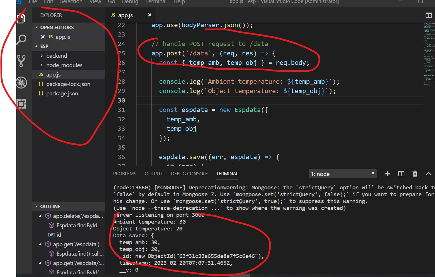
// handle POST request to /data
app.post('/data', (req, res) => {
const { temp_amb, temp_obj } = req.body;
console.log(`Ambient temperature: ${temp_amb}`);
console.log(`Object temperature: ${temp_obj}`);
const espdata = new Espdata({
temp_amb,
temp_obj
});
espdata.save((err, espdata) => {
if (err) {
console.error(err);
res.status(500).send('Error saving data');
} else {
console.log(`Data saved: ${espdata}`);
res.status(201).send('Data saved');
}
});
});
// handle GET request to /espdata
app.get('/espdata', (req, res) => {
Espdata.find((err, espdata) => {
if (err) {
console.error(err);
res.status(500).send('Error retrieving data');
} else {
res.json(espdata);
}
});
});
// handle GET request to /espdata/:id
app.get('/espdata/:id', (req, res) => {
const { id } = req.params;
Espdata.findById(id, (err, espdata) => {
if (err) {
console.error(err);
res.status(500).send('Error retrieving data');
} else if (!espdata) {
res.status(404).send('Data not found');
} else {
res.json(espdata);
}
});
});
// handle PUT request to /espdata/:id
app.put('/espdata/:id', (req, res) => {
const { id } = req.params;
const { temp_amb, temp_obj } = req.body;
Espdata.findByIdAndUpdate(id, { temp_amb, temp_obj }, { new: true }, (err, espdata) => {
if (err) {
console.error(err);
res.status(500).send('Error updating data');
} else if (!espdata) {
res.status(404).send('Data not found');
} else {
res.json(espdata);
}
});
});
// handle DELETE request to /espdata/:id
app.delete('/espdata/:id', (req, res) => {
const { id } = req.params;
Espdata.findByIdAndDelete(id, (err, espdata) => {
if (err) {
console.error(err);
res.status(500).send('Error deleting data');
} else if (!espdata) {
res.status(404).send('Data not found');
} else {
res.status(204).send();
}
});
});
app.delete('/delete',(req,res)=>{
Espdata.remove(()=>{
res.send("collection removed");
})
})
// start server
app.listen(port,()=>{
console.log(`server listening on port ${port}`)
})
Code Explanation
This code is a Node.js server using the Express framework to handle HTTP requests. I t also uses Mongoose to connect to a MongoDB database and define a data model.
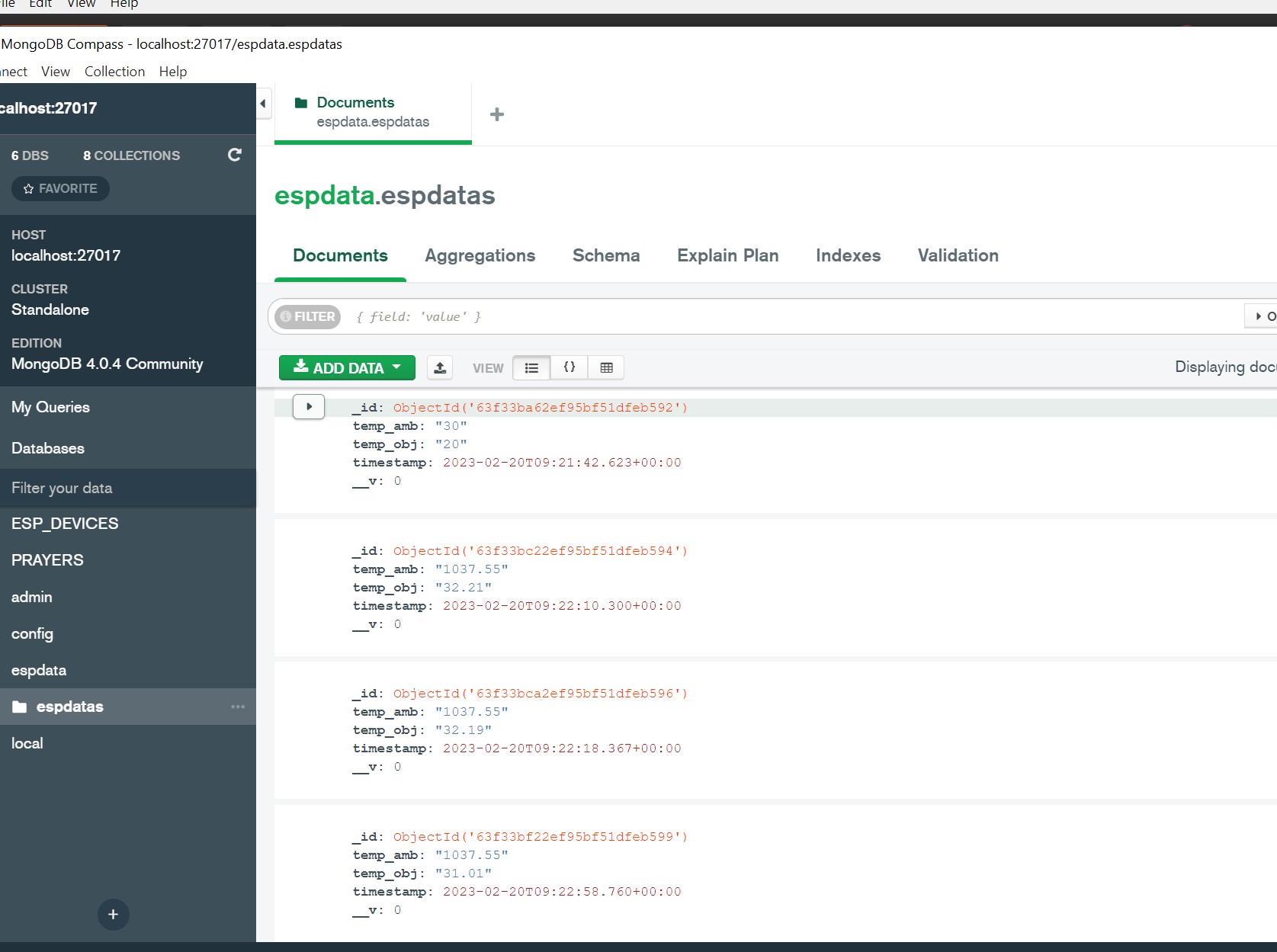
The code begins by importing the required modules (Express, Body-parser, and Mongoose) and creating an instance of the Express app. It also specifies the port on which the server should listen for incoming requests. The next part of the code sets up a connection to a MongoDB database called "espdata" and defines a Mongoose schema for the data that will be stored. The schema has three fields: a timestamp (which is automatically set to the current time), and two temperature fields - one for ambient temperature and one for object temperature. The schema is then used to create a Mongoose model called "Espdata".
The next part of the code sets up middleware to parse incoming JSON payloads, using the Body-parser module. It then sets up various route handlers to handle incoming HTTP requests to the server. The first route handler ("/data1") simply logs the request body and sends a response. The next route handler ("/data") handles a POST request that contains temperature data in the request body. It extracts the temperature values from the request body, creates a new instance of the Espdata model with those values, and saves it to the database. If the save operation is successful, it sends a "201 Created" response; if there is an error, it sends a "500 Internal Server Error" response. The next three route handlers handle GET, PUT, and DELETE requests for individual records in the Espdata collection. They retrieve the record by ID, update it, or delete it as appropriate, and send an appropriate response. The final route handler ("/delete") simply deletes all records in the Espdata collection. Finally, the code starts the server and logs a message to indicate that it is listening for incoming requests.
Output