Week 2: Computer Aided design
Assignment
- Model (raster, vector, 2D, 3D, render, animate, simulate, ...) a possible final project, compress your images and videos, and post it on your class page
Learning Outcomes
- Evaluate and select 2D and 3D software
- Demonstrate and describe processes used in modelling with 2D and 3D software
WEEK 2 WORK ORGANIZATION
- Raster vs vector images
- 2D vs 3D design Models
- 2D Modeling with photoshop (raster)
- 2D Modeling with GIMP (raster)
- Conclusion about use of photoshop and gimp
- 2D Modeling with coreDraw (vector )
- 2D Modeling with inkscape(vector )
- 3D Modeling with SolidWORKS
- 3D Modeling with FreeCAD
- Final Project Cover Box Modeling
- Rendering and Simulation
- Challenges faced
- Original Design Files
Raster vs vector images
As a new student in designing, i had even no skills about pictures and images formats, and i knew rasta and vector terms onc ei joined fab Academy. i did some research on internet in order to familiar with those terms and real world application.
What i Have seen while documenting my self is that Raster images and vector graphics have different purposes in design, and it is essential for you to understand when and where to use them for the right purpose.
What is a rasta ffiles?
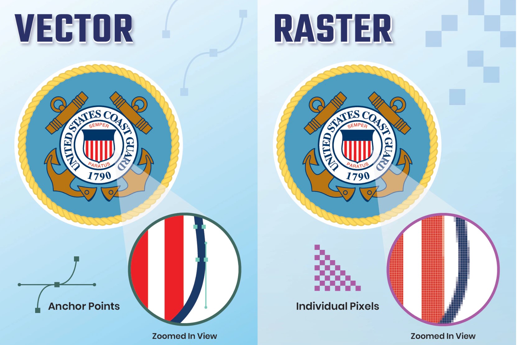
According to adobe Raster files are images built from pixels — tiny color squares that, in great quantity, can form highly detailed images such as photographs. The more pixels an image has, the higher quality it will be, and vice versa. The number of pixels in an image depends on the file type example, JPEG, GIF, or PNG
What is a vector file??
According to adobe Vector files use mathematical equations, lines, and curves with fixed points on a grid to produce an image. There are no pixels in a vector file. A vector file’s mathematical formulas capture shape, border, and fill color to build an image. Because the mathematical formula recalibrates to any size, you can scale a vector image up or down without impacting its quality.
Rasta vs Vector Specifications
The two most widely used file types for visual material are raster and vector files. There are several factors to take into account when picking which one to employ because they depict images in quite diverse ways. The following are some of the primary distinctions between raster and vector:
Resolution
The resolution of raster and vector files is one of their primary differences. A raster file's resolution is expressed in DPI (dots per inch) or PPI (pixels per inch). Raster images allow you to zoom in or increase their size so that you can see the individual pixels. Raster files show a broader variety of colors than vector files, allow for more color tweaking, and display finer light and shade, but they lose image quality when scaled. Increasing an image's size is a simple approach to determine whether it is raster or vector. The image is most likely a raster file if it blurs or becomes pixelated. The resolution of vector picture files is unimportant. Vectors can be infinitely resized, rescaled, and reshaped.
Use
Most digital photos are raster files. Raster files are often created and saved automatically by many digital cameras, and they are also frequently used for web photographs. Raster files are frequently employed for modifying graphics, pictures, and images. For digital artwork, intricate graphics, and logos, vector files are preferable. That's because vectors can be enlarged without losing resolution, making them appropriate for a wide range of printed formats. In certain projects, vector and raster pictures are combined. For instance, a brochure might utilize raster images for the photos but vector graphics for the corporate logo.
File Size
In general, raster files are bigger than vector files. They can have a staggering amount of detail and millions of pixels. Their size can limit device storage and impede the web's ability to load pages quickly. Raster files can, however, be compressed for online optimization and storage to speed up and simplify sharing. Compared to raster files, vector files are significantly smaller because they just provide the mathematical equations that determine the design.
Compatibility and Conversion
You can open raster files in many different apps and web browsers, making them easy to view, edit, and share. Vector files aren’t as accessible — many vector file types require specialized software to open and edit the files. Though it can present some challenges, it’s possible to convert vector files to raster or raster files to vector when needed.
Software that deals with raster files are like photoshop, picasa , GIMP etc..
2D vs 3D design Models
After getting familiar with raster and vector files , then i moved forward by doing research on 2D and 3D models, undestanding similarities and differences. i have used interbet resources and the following informations have helped me to start my designing jouney with solid back round.
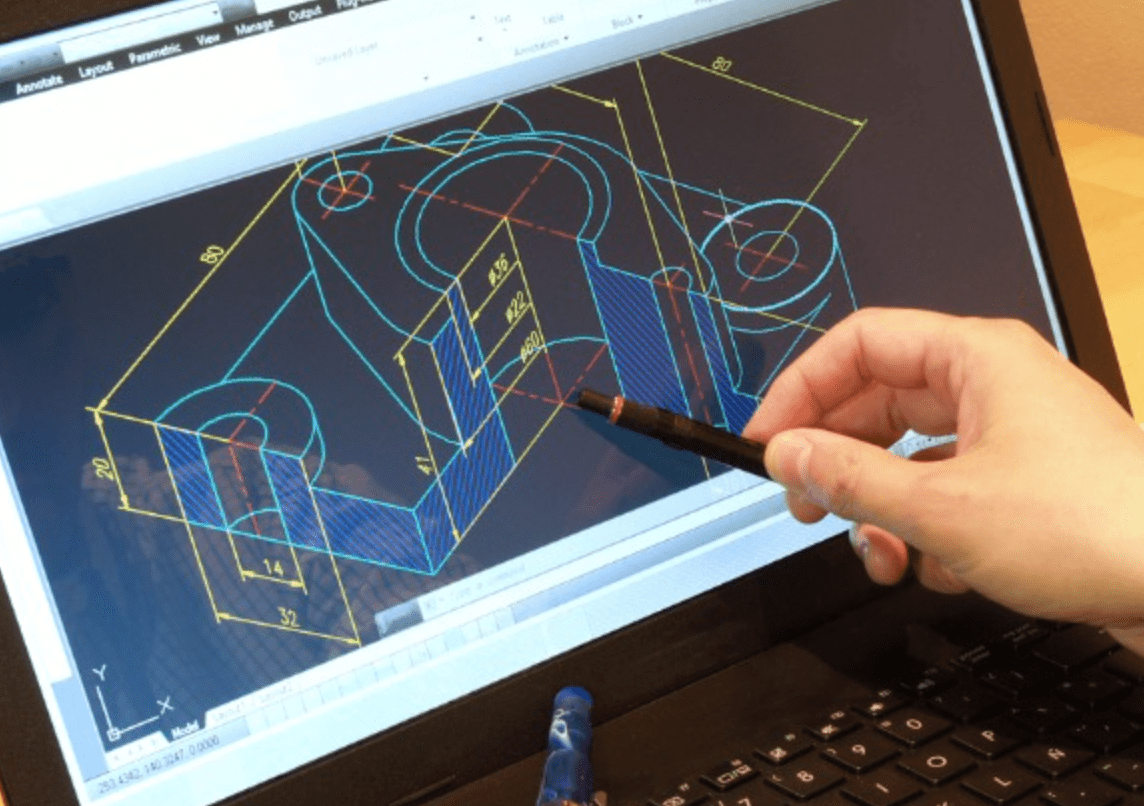
According to Manufacturing tomorrow website, the past years designers once had to create part drawings with basic materials like paper and a pencil. The manufacturing industry's design and production processes evolved with the introduction and widespread use of CAD software, which eventually made its way into the CNC machining process. Drawing is more mechanized and accurate when done with CAD files, which are typically used for mechanical design and manufacturing. Using CAD files, you can zoom in on the 3D model and rotate on any axis to better comprehend the pieces. You can also check out every detail of a part, including internal characteristics. Additionally, CAD enables the simulation of the workpiece's movement during the CNC production process.
2D Modeling with photoshop (raster)
To be familiar with photoshop, i followed online tutorial
Firstly i downladed photoshop via photoshop web
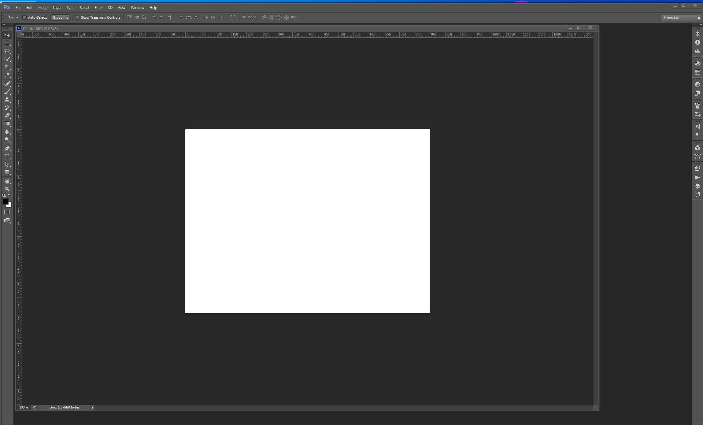
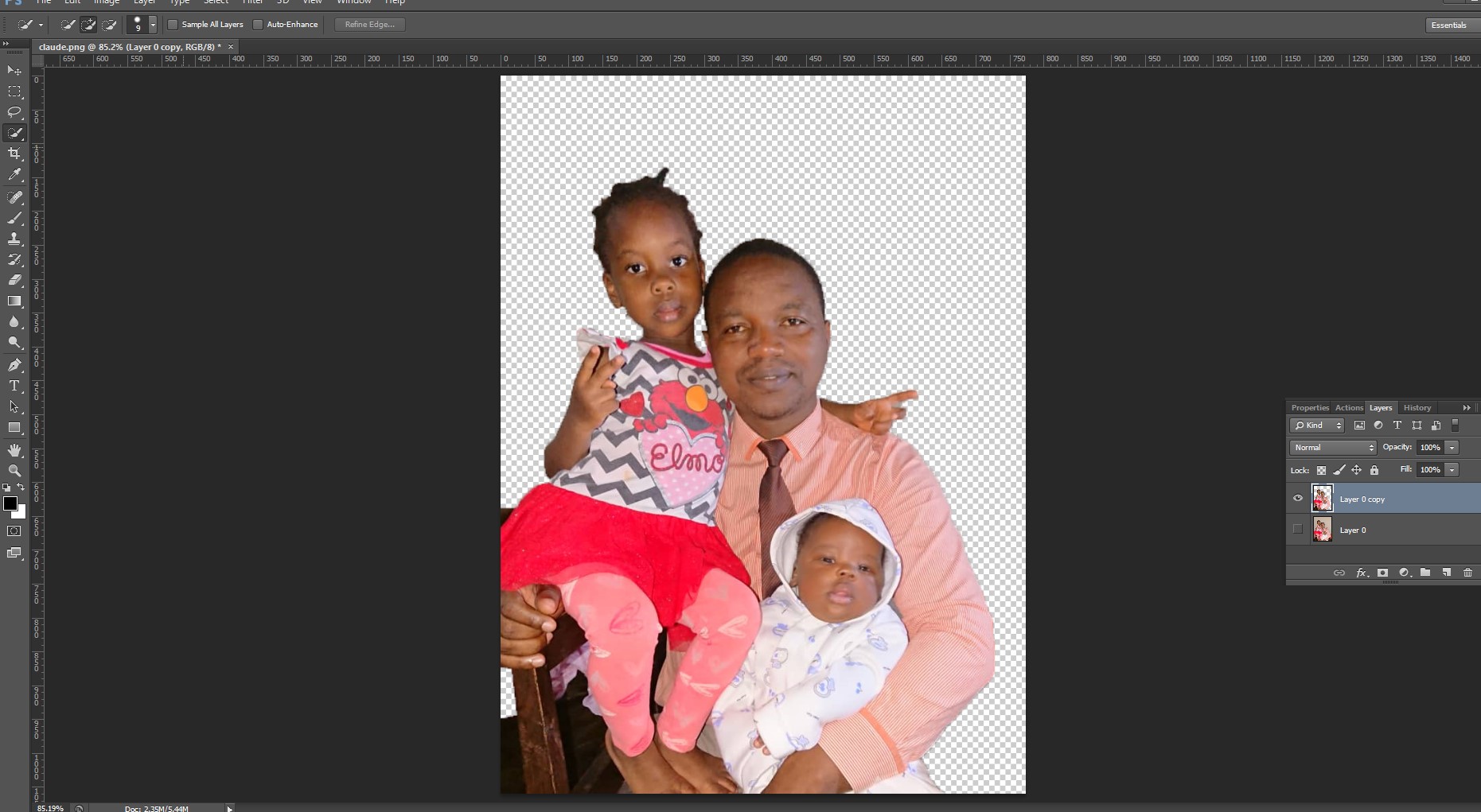
The following is the photoshop interface once opened
2D Modeling with GIMP (raster)
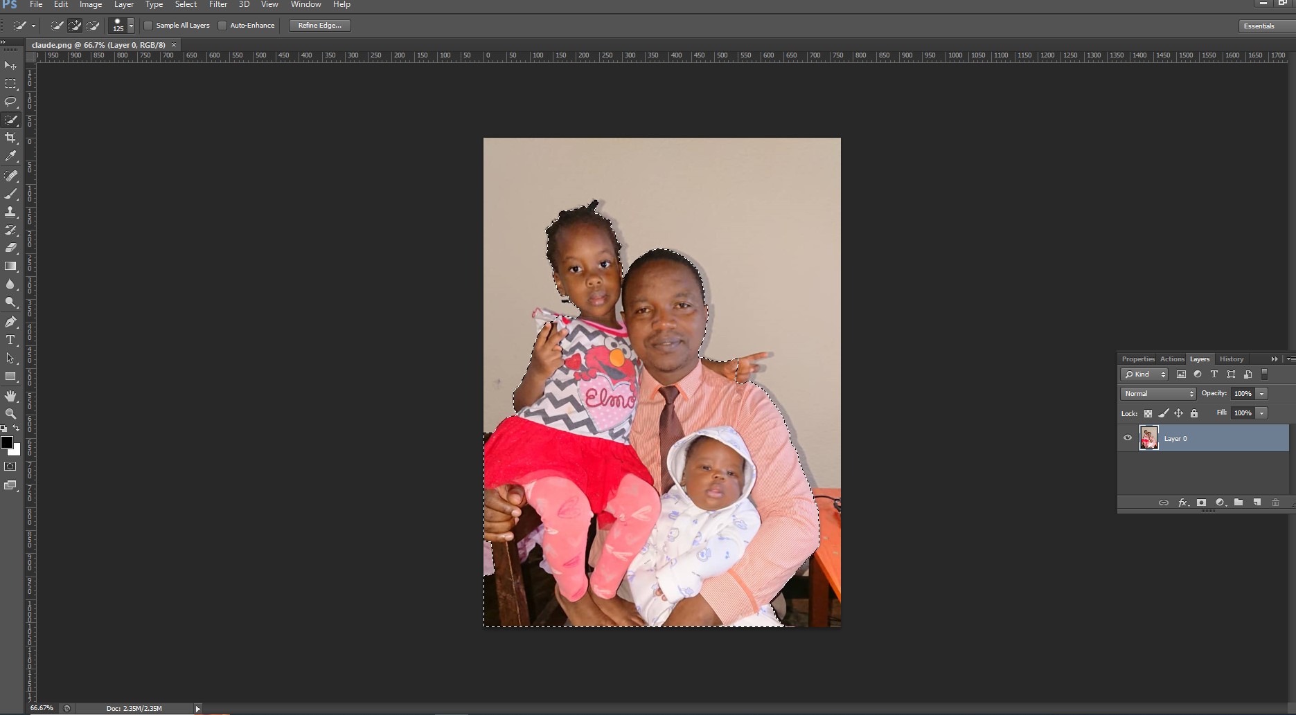
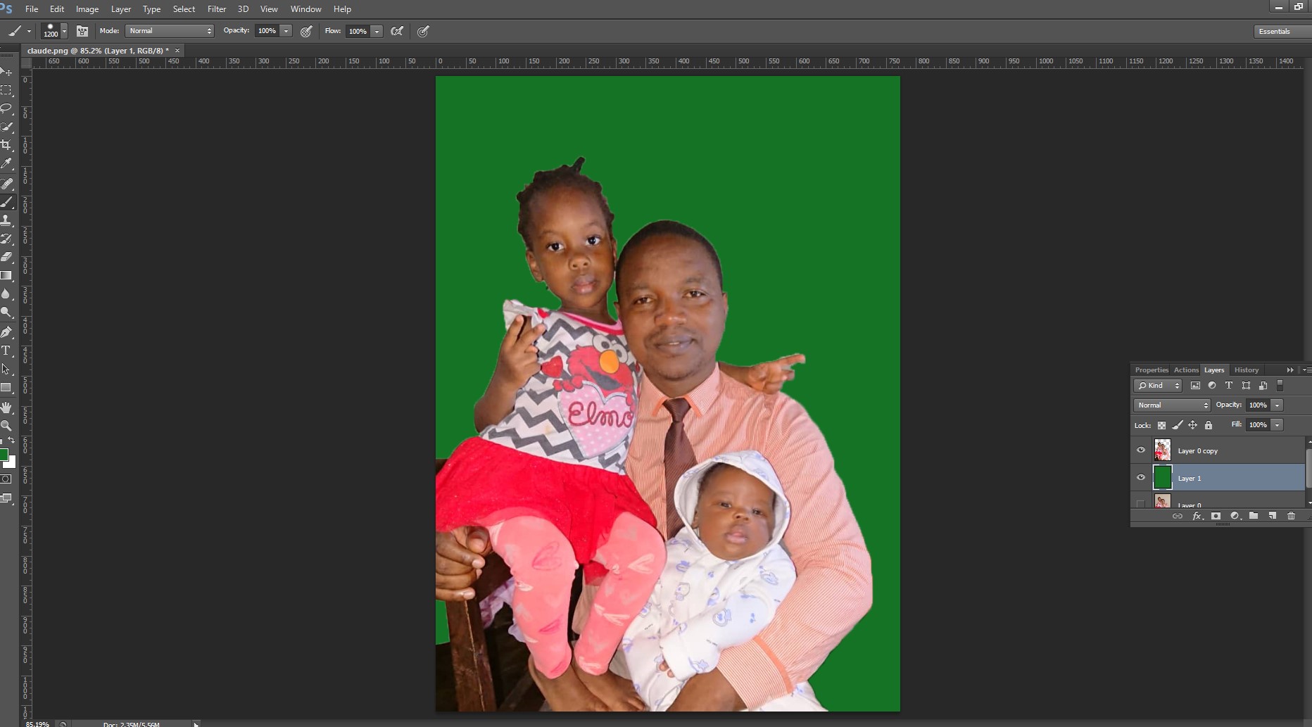
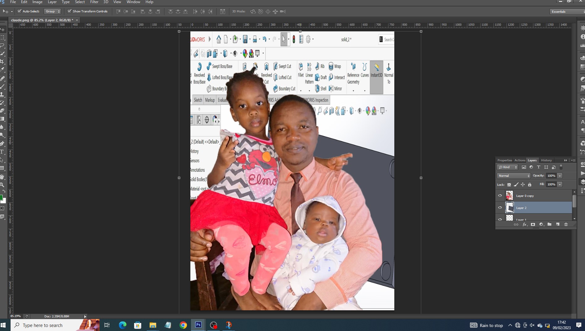
as i had no backgroud about Gimp, it was very difficult even to import image. it required me to look at onlien tutotials on youtube to be able to use it. what i did is to remove the picture backgound and enhance its colours.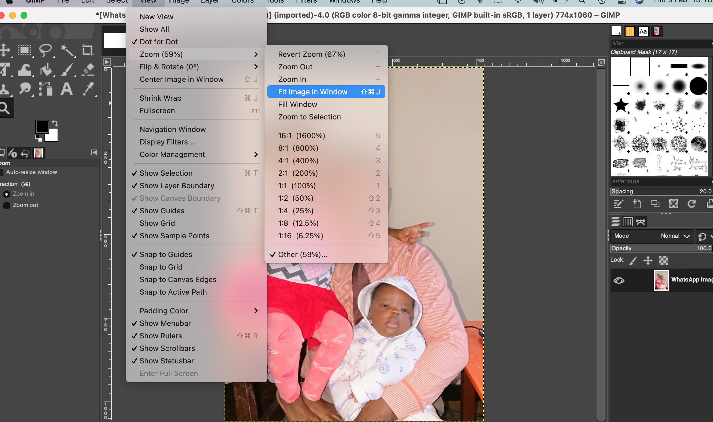
to fit image in screen center you go to view>zoom>fit Image in Window
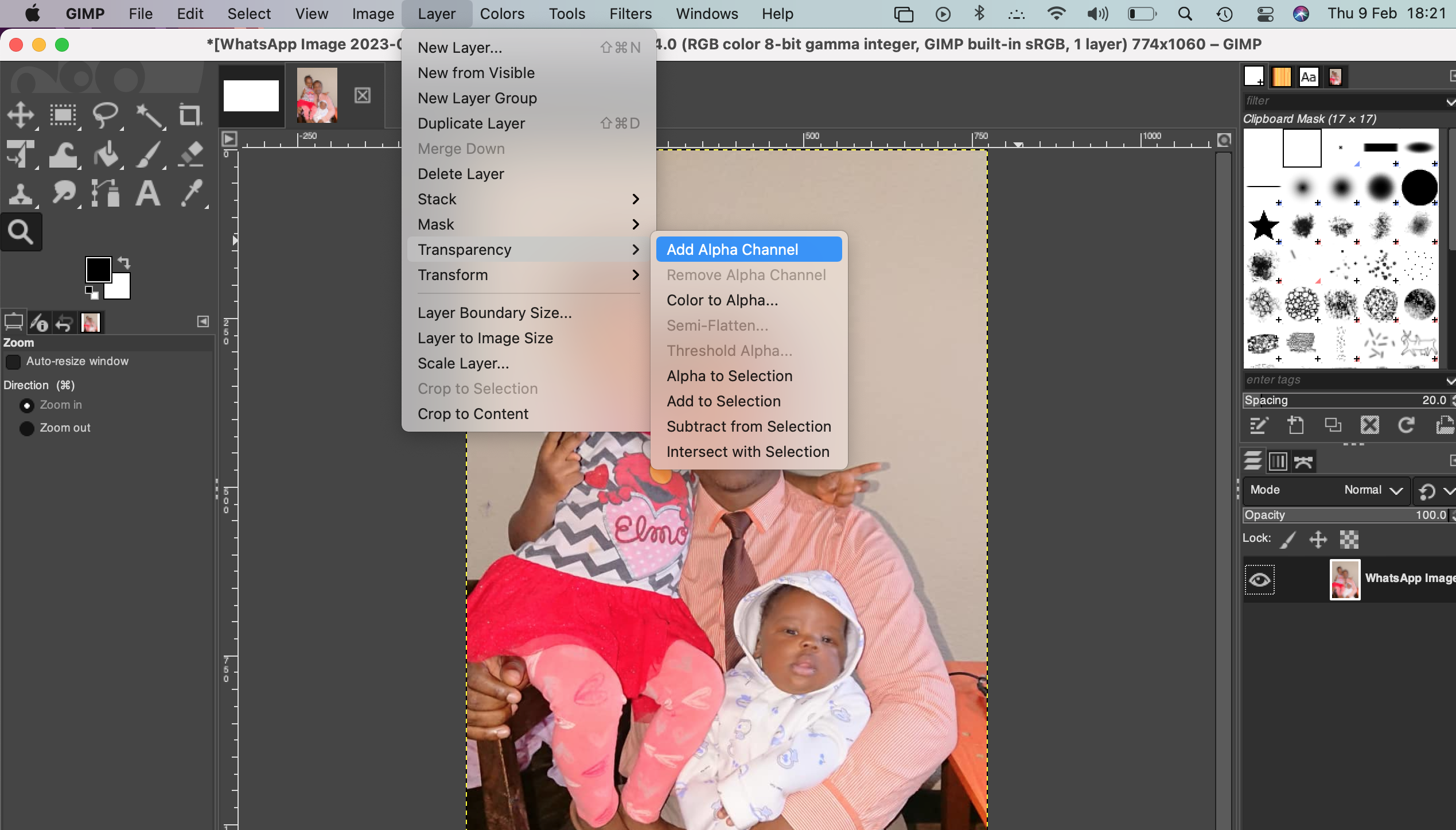
An alpha channel in Gimp is created as an additional channel alongside the RGB color channels and allows you to save the transparency settings of an image or selection. Alpha channels are used to save selections for later use or to share selection information between editing programs. to create transparency you go to layers>transparency>add alpha channel
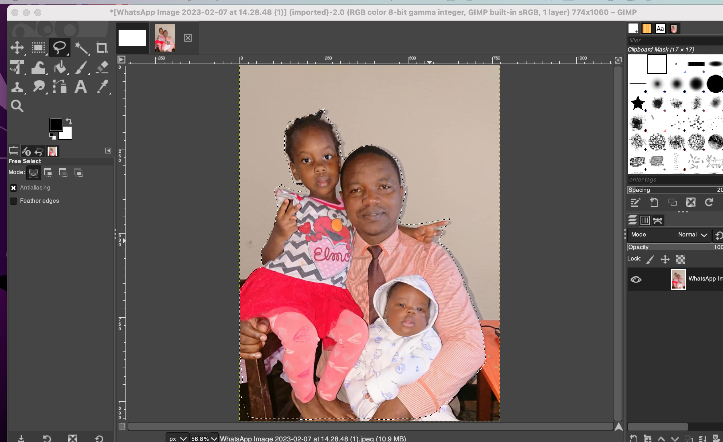
To select image area, i have used free selection tool.
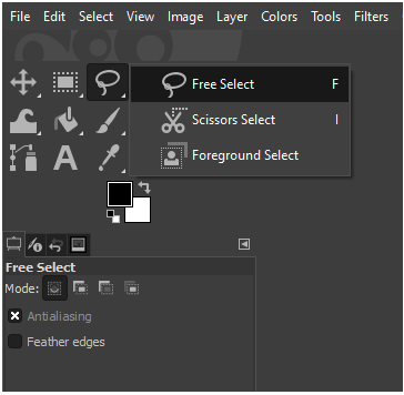
selecting tool in gimp
After selection with select tool
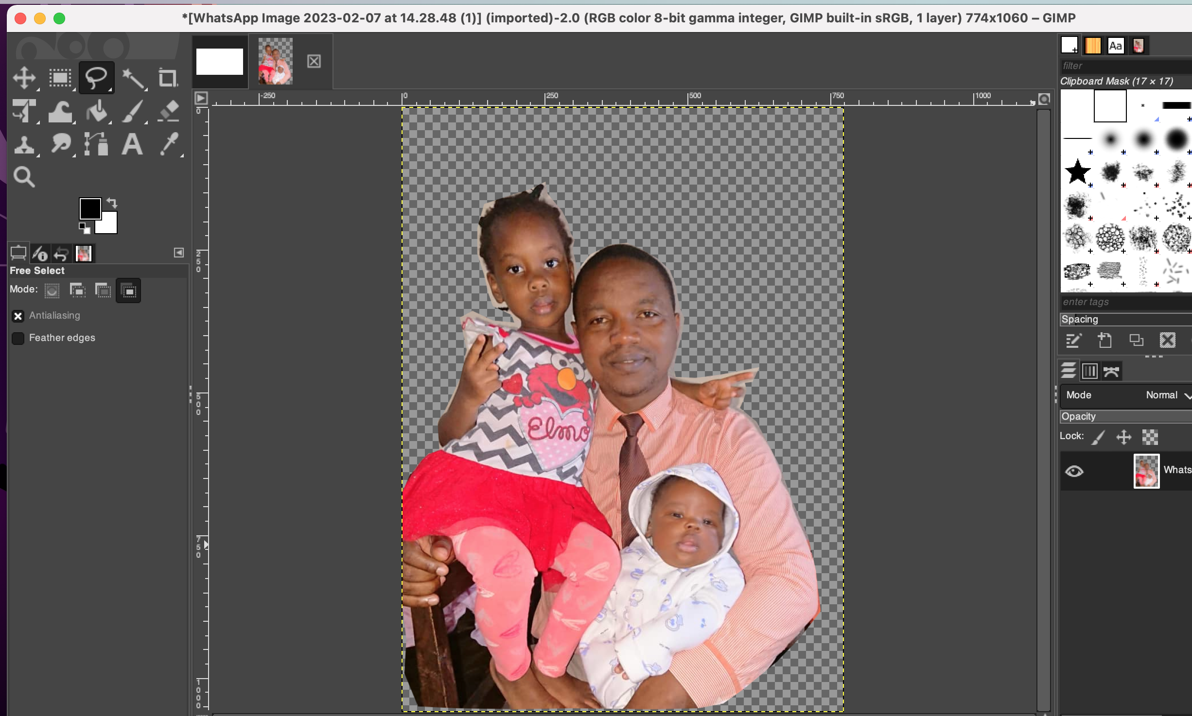
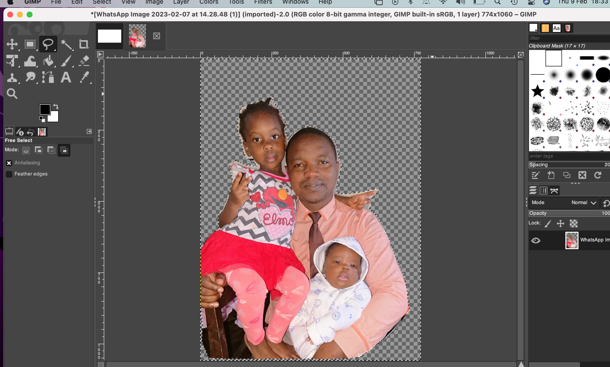
Removing backgroudn
Deselect background area
As a starter in using photo editing tool , it took me many hours even to know how to do simple selection . But i watched tutorials and i hope that i will be famillair with them as long as i keep using the tool.
Conclusion about use of photoshop and gimp
Adobe photoshop seems to be complex compared to gimp in terms of use. it is difficult to a beginner to get started with photoshop because is has many tools to use and layers which are complex to understand how image processing is done with many layers.
Adobe Photoshop and GIMP are two of the most popular image editing software, but they differ significantly in terms of performance, complexity, and usability.
Performance:
In terms of performance, Photoshop is considered to be the industry standard, and is widely used by professional photographers and graphic designers. It has powerful features and tools for photo editing and manipulation, and is optimized for use on high-end computers. On the other hand, GIMP is a free and open-source alternative, and may not be as fast as Photoshop on lower-end computers.
Complexity:
Photoshop has a large number of features and tools, making it a very complex software to use. It has a steep learning curve, and it may take some time for a beginner to get used to its interface and features. On the other hand, GIMP has a relatively simpler interface, and is easier to learn and use. It may not have as many advanced features as Photoshop, but it still provides a good range of tools for basic photo editing and manipulation.
Usability:
hotoshop has a more professional interface, and its layout is optimized for power users. It also has a large community of users, and there are many online resources available to help you learn how to use it effectively. On the other hand, GIMP has a more beginner-friendly interface, and its layout is easier to navigate. It is also highly customizable, allowing users to personalize their experience.
Overall Conclusion
In conclusion, both Photoshop and GIMP are great image editing software, but they are suited for different purposes. If you are a professional photographer or graphic designer, Photoshop is the better choice. However, if you are a beginner or hobbyist, GIMP is a great starting point, as it is free and easier to use. for me i prefer photoshop cause of great features it provides
2D Modeling with coreDraw (vector )
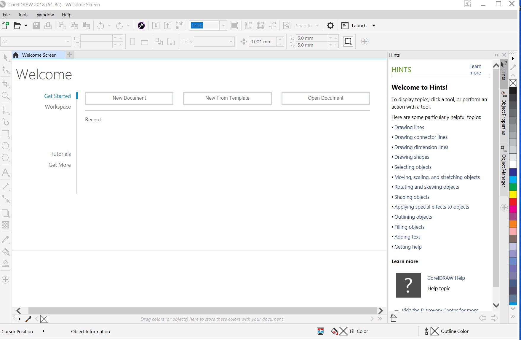
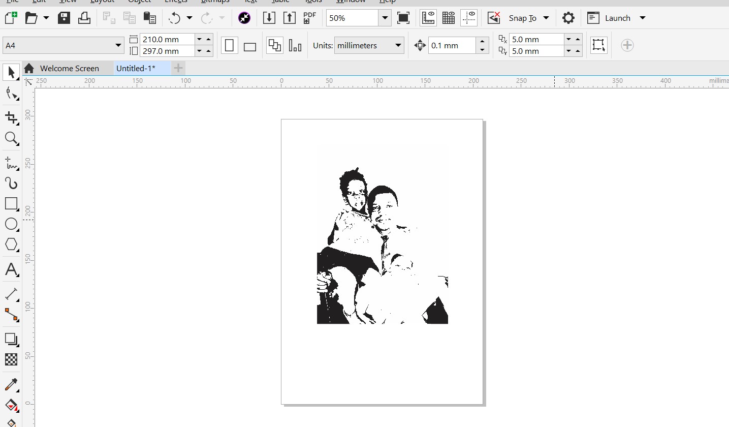
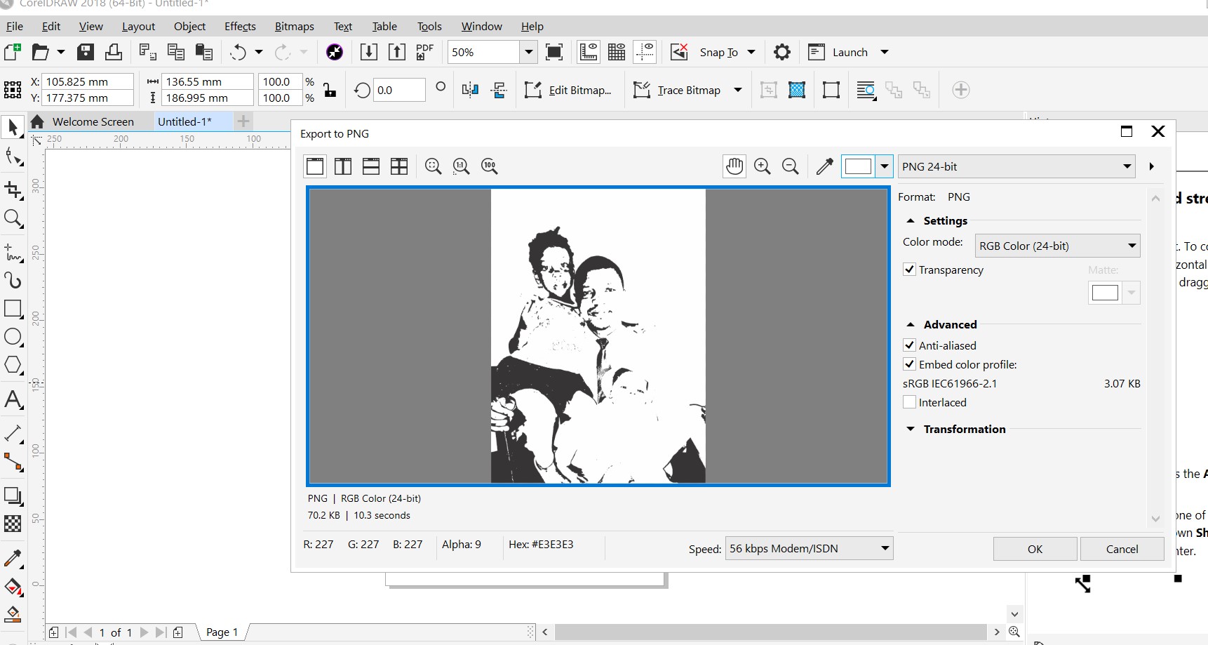
It is the first time for me to use coredraw but i have heard about the software from my friend who was dealing with vinyl cutter for writing characters on clothes. to get started with coreDraw, i have watched online youtube tutorials and then i have seen how to get image outlines, create image vector and prepare an image for laser cutter to be printed on wooden materials
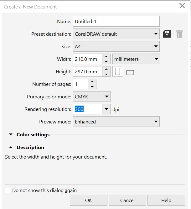
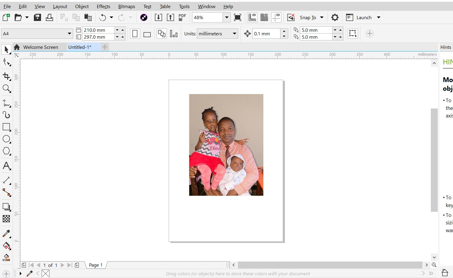
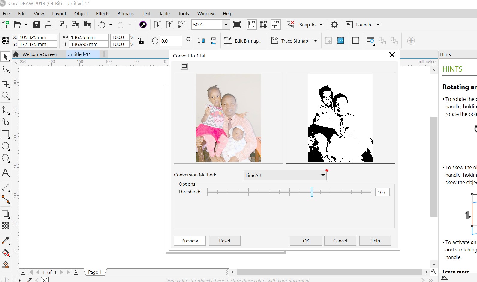
The following tutorials illustrates the processes i get through whiletrying to prepare my first image for laser cutter by converting image_missingproperties and save it black and white
I got coredrawthrough here
Then installation is normal in windows, just launch the app and click next next by selecting only default installation guide provided
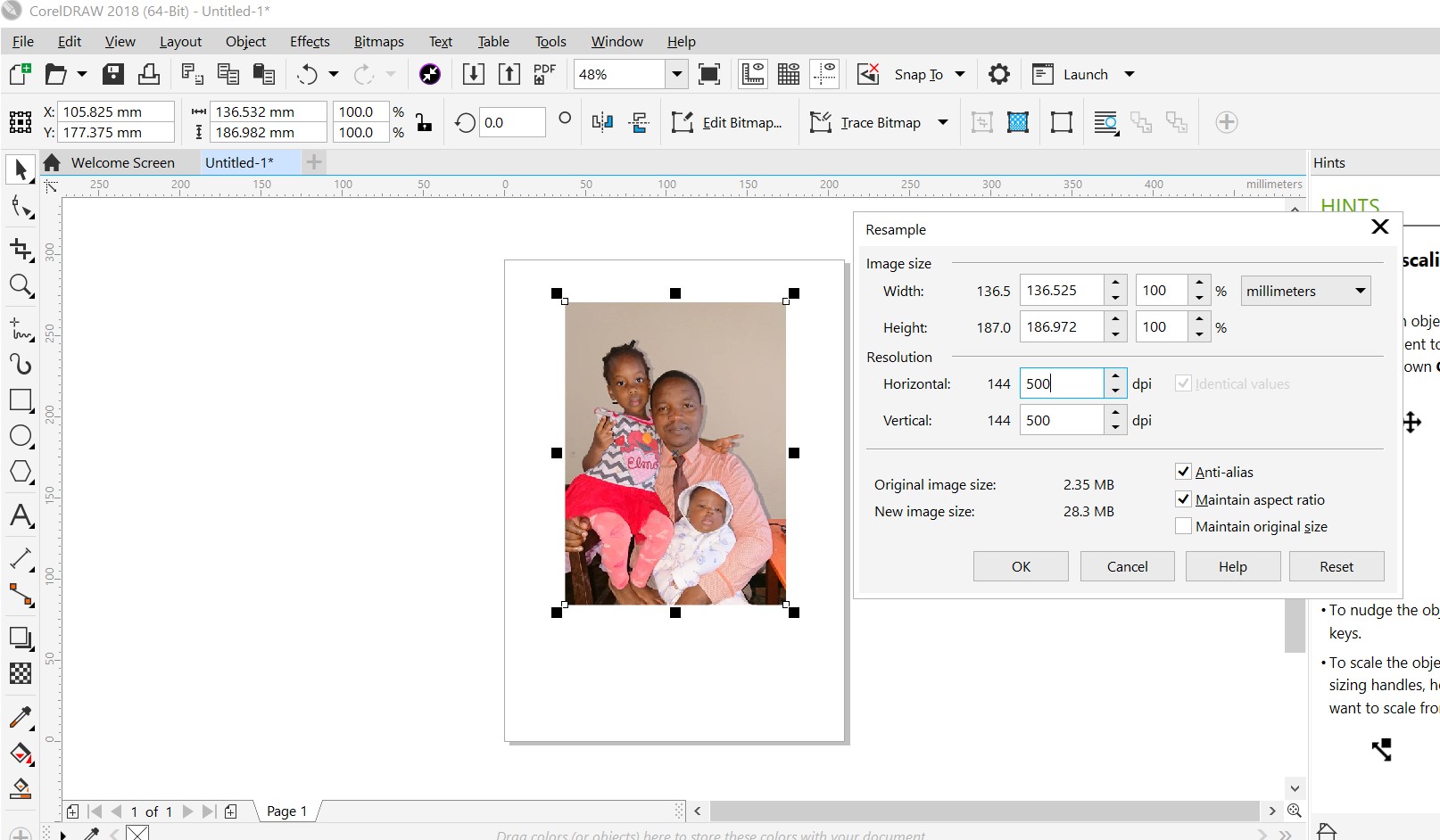
In CorelDRAW, resampling is the process of changing the resolution of an image. can involve either increasing or decreasing the number of pixels in the image, resulting in either a more detailed or a less detailed version of the image, respectively. The resampling process is used to adjust the size of an image for various purposes, such as printing, display on a screen, or to prepare an image for further editing.
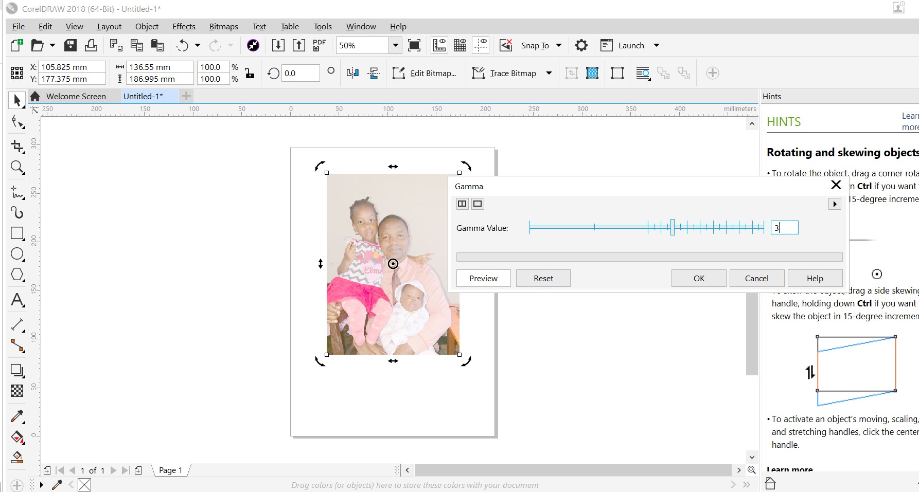
In CorelDRAW, gamma correction is a color correction technique used to adjust the brightness and contrast of an image. The gamma value determines the relationship between the brightness of an image and the numerical values assigned to each pixel in the image. By adjusting the gamma value, you can make an image appear brighter or darker, or adjust the contrast between the light and dark areas of the image. The purpose of gamma correction is to ensure that an image appears correctly on different devices and displays, as different devices may interpret the same brightness values differently.
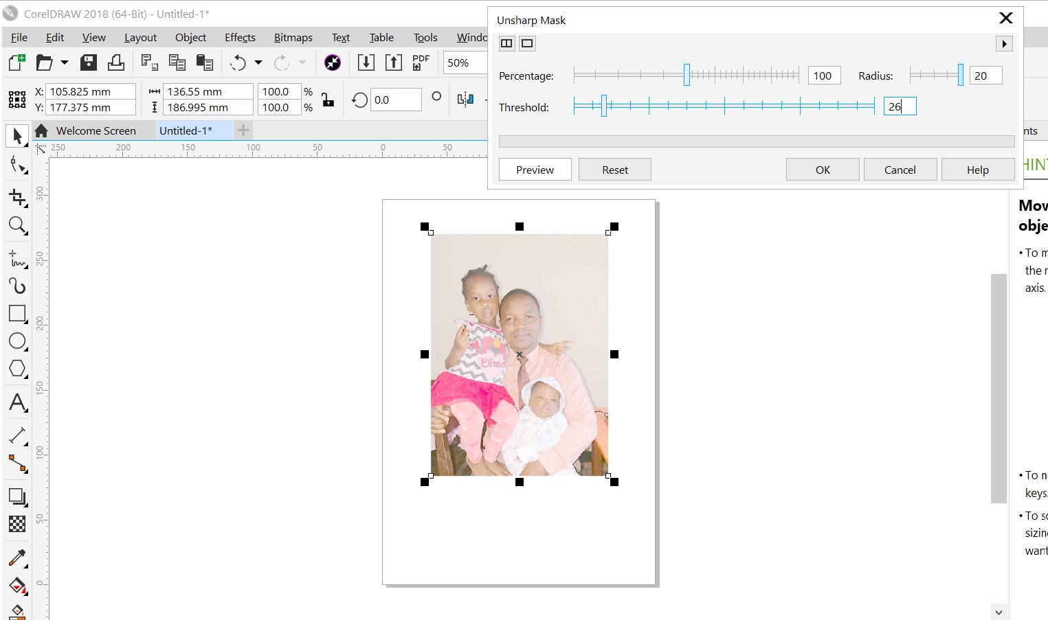
The Unsharp Mask tool in CorelDRAW is a sharpening tool used to increase the clarity and detail of an image by enhancing its edges and fine details. It works by creating a blurred copy of the original image and then subtracting that blurred image from the original image. The result is an image with increased contrast along edges and fine details, which gives the image a sharper appearance. The Unsharp Mask tool can be used to correct images that are blurry or soft, or to enhance images that are lacking in detail. By adjusting the various parameters of the tool, such as the radius, threshold, and amount, you can control the extent and intensity of the sharpening effect applied to the image.
The Sharpen tool in CorelDRAW is a sharpening filter that is used to increase the clarity and detail of an image. Unlike the Unsharp Mask tool, the Sharpen tool applies a simple filter to the image that increases the contrast of pixels along edges and fine details, giving the image a sharper appearance. The Sharpen tool is a quick and easy way to improve the clarity of an image, and can be useful for correcting blurry or soft images, or for enhancing images that are lacking in detail. By adjusting the strength of the filter, you can control the extent and intensity of the sharpening effect applied to the image. The Sharpen tool can be used as an alternative to the Unsharp Mask tool, but it does not provide as much control over the sharpening effect.

The purpose of converting a 1-bit black and white image to an 8-bit grayscale image is to increase the number of shades of gray that can be represented in the image. By using more bits to represent each pixel, a grayscale image can have more levels of intensity, leading to a more nuanced and detailed representation of the original image. This can be useful in various applications, such as image editing, digital printing, or when trying to produce a more visually appealing image for display or presentation purposes.
2D Modeling with inkscape(vector )
content to be filled after !!!!!!
3D Modeling with SolidWORKS
SolidWorks is a computer-aided design (CAD) software application used for creating 3D mechanical designs and simulating product behavior. It is widely used in industries such as aerospace, automotive, and consumer goods to design and manufacture products.
To get started with SolidWorks, i followed this steps suggested via to get familiar with it and i consuled the following guides and tutorials
- SolidWorks official website - provides tutorials, documentation, and resources for learning the software.
- SolidWorks YouTube channel - offers video tutorials and demos to help you learn the software.
- SolidWorks community - a platform where you can connect with other SolidWorks users and ask questions or get help with specific issues.
- SolidWorks online training - provides online courses and certification programs to help you learn the software more thoroughly.
- SolidWorks blog - features articles and resources on how to use SolidWorks effectively and improve your skills.
- Coursera - offers online courses in SolidWorks, including introductory and advanced courses.
- Install the SolidWorks software on your computer . follow this tutorial on youtube
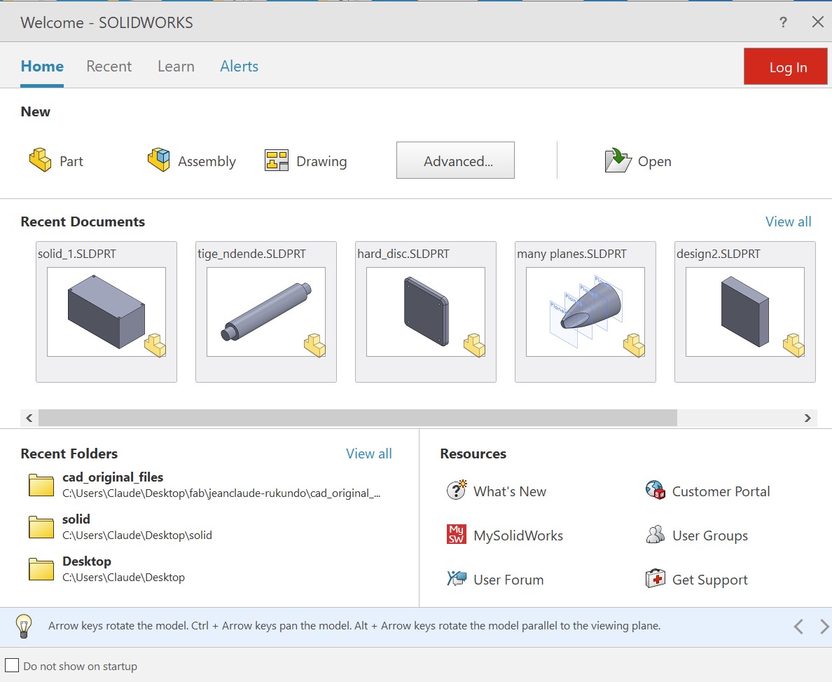
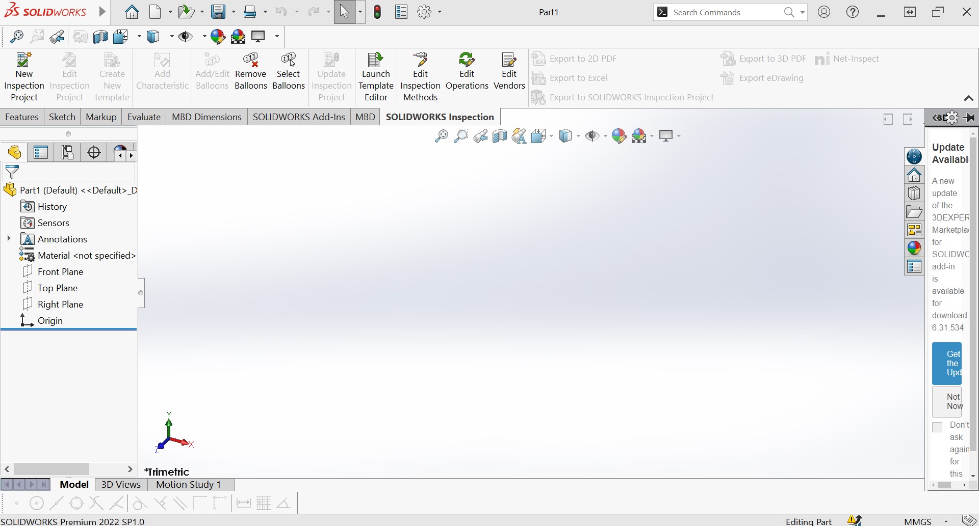
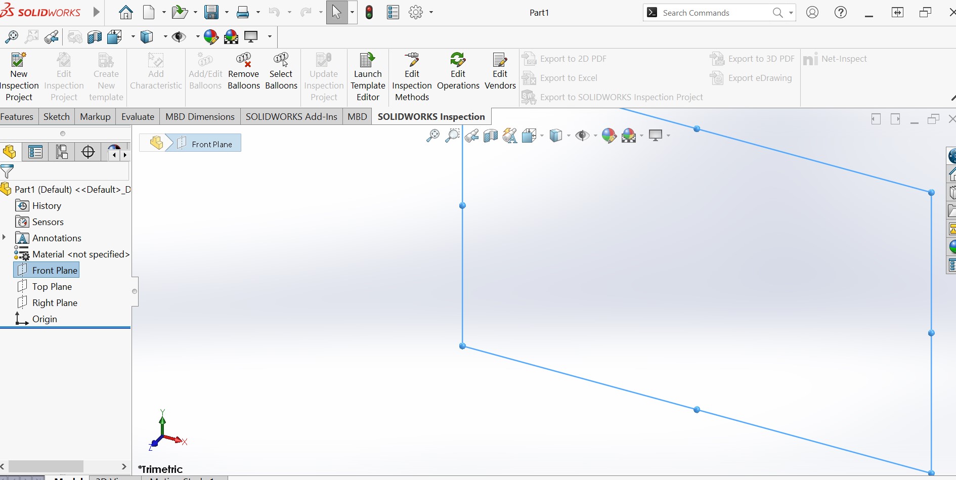
- Launch the SolidWorks application and familiarize yourself with the user interface.
- Study the SolidWorks tutorials and documentation provided in the help menu to learn about the various tools and features.
- Start with simple projects to get a feel for the software and gradually work your way up to more complex designs.
- Consider enrolling in online courses or attending training sessions to learn the software more thoroughly and to receive more in-depth knowledge and skills.
Starting with SolidWORKS
I have followed this youtube tutorial because they show how to make box cover of electronic circuit. this is what i need because in need cover for my final project circuit.
Making my first Box cover of my final project in solidworks
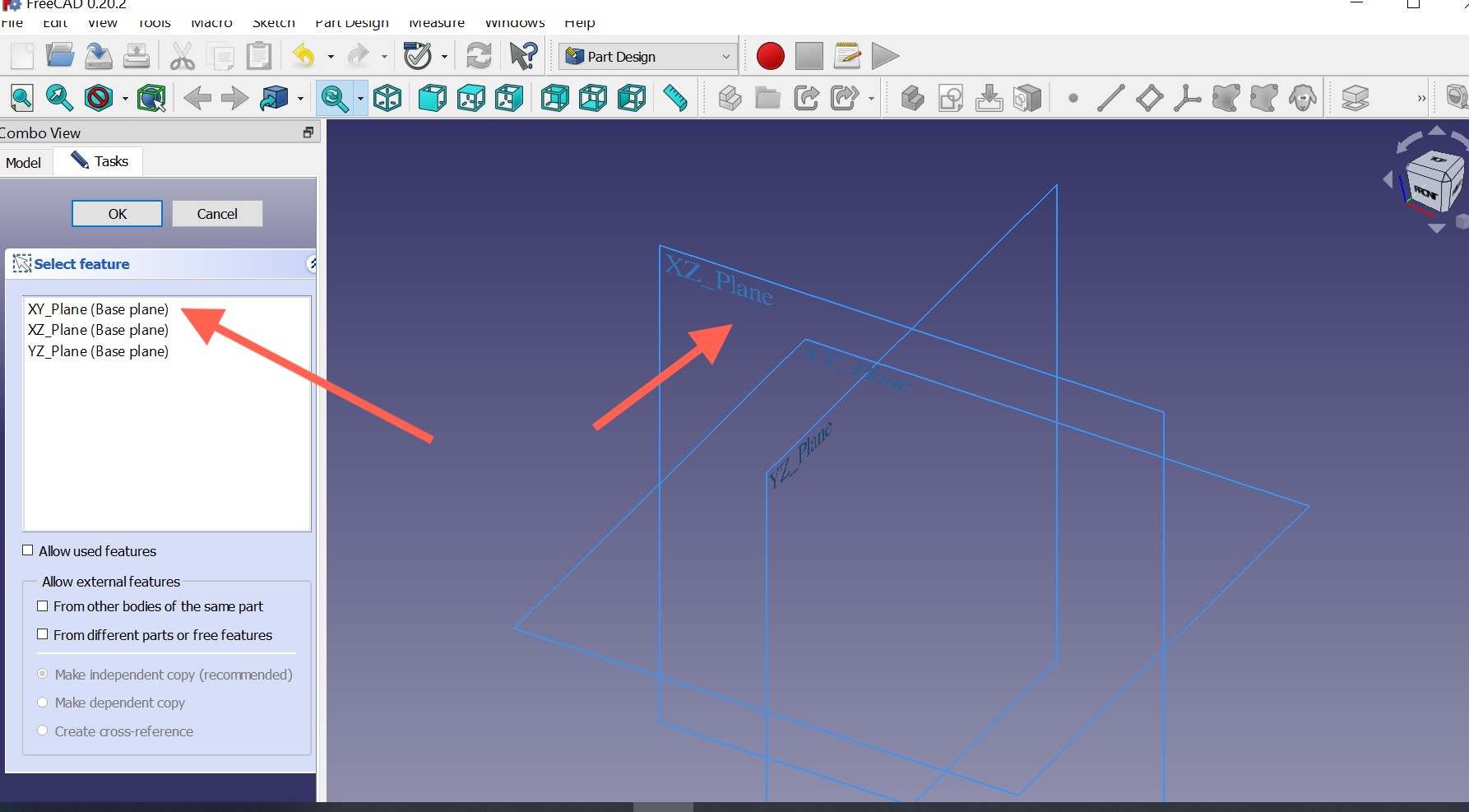
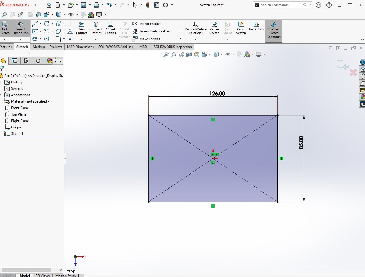
The first thing is to select a plane for your part. 3D software has XYZ coordinates meaning it has top plane, fornt plane and right plane.
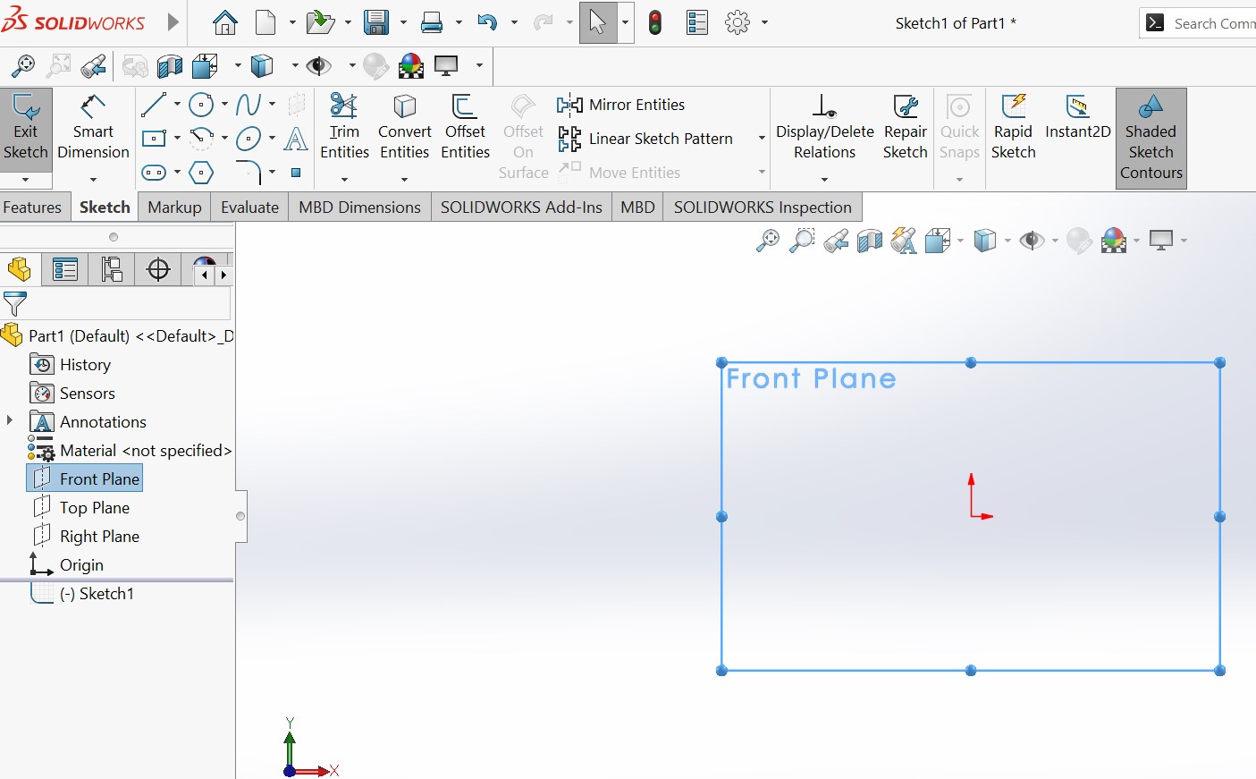
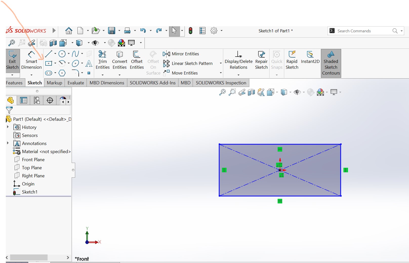
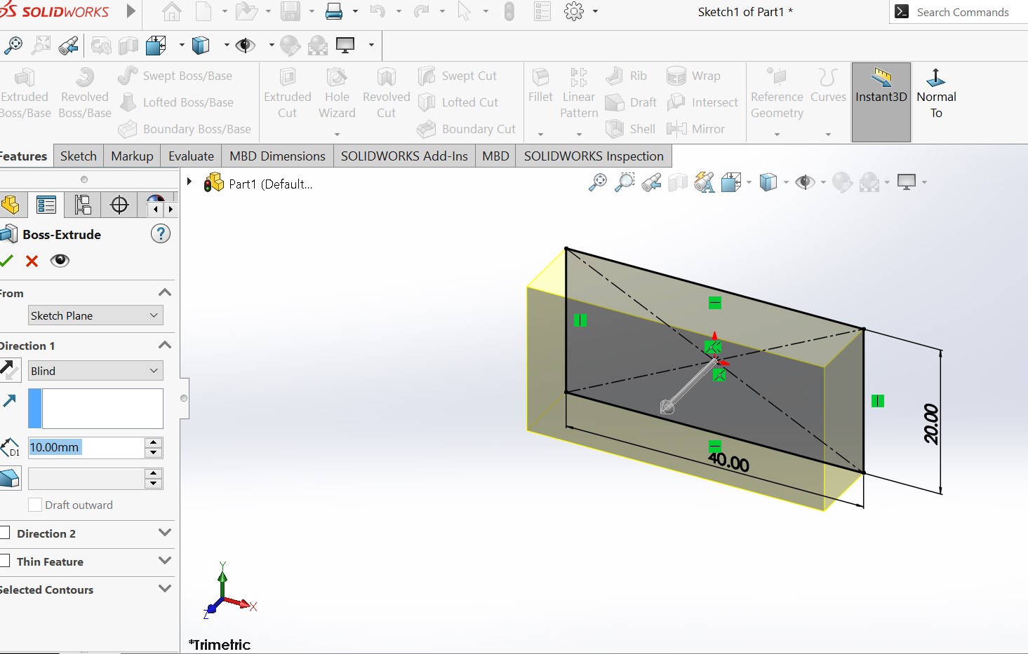
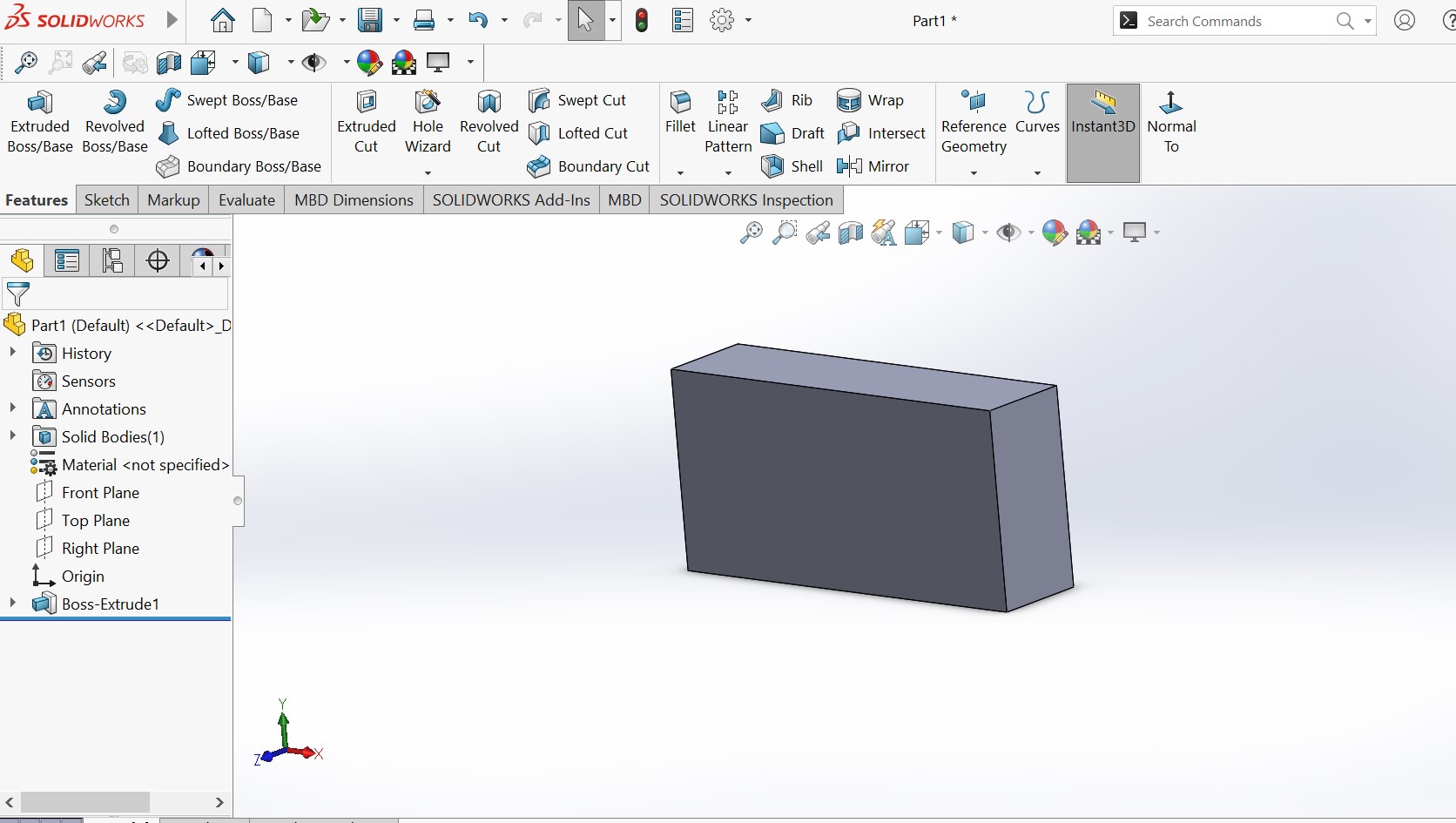
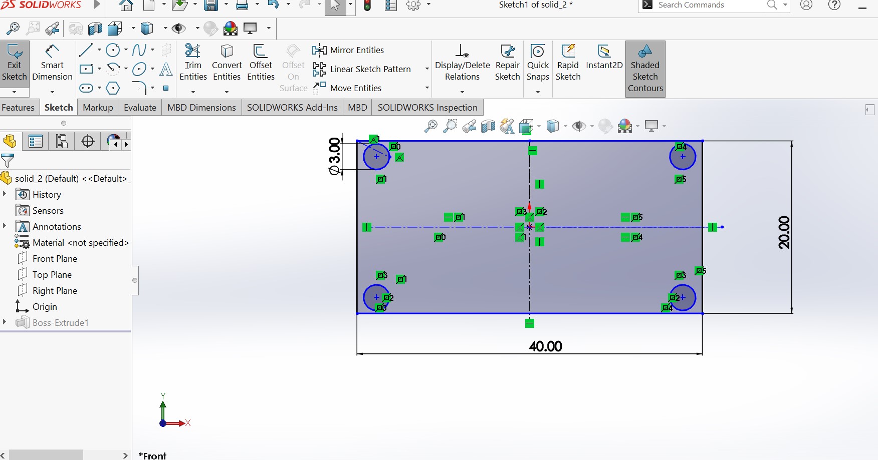
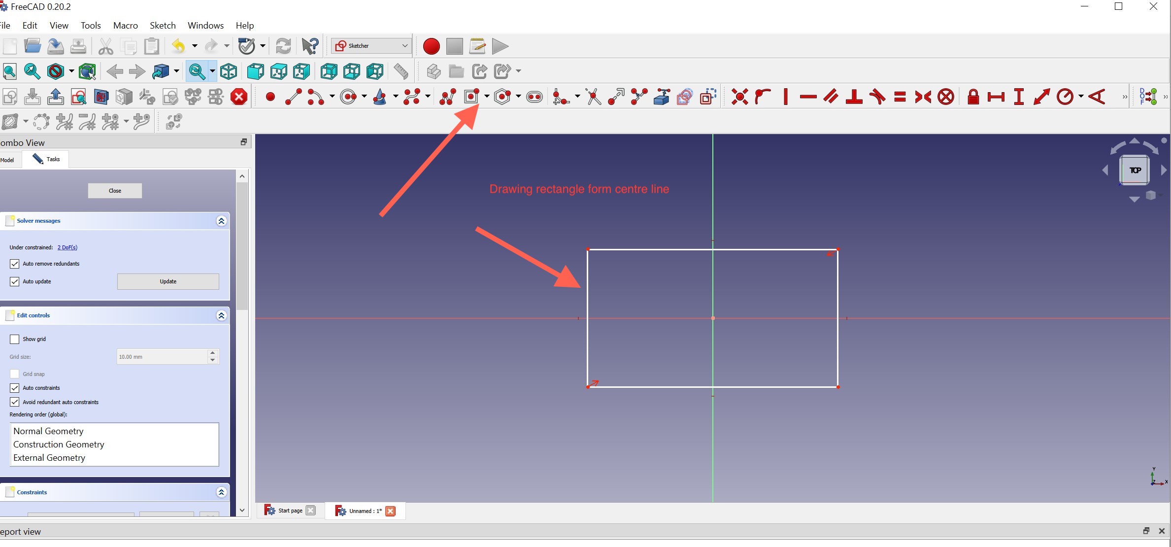
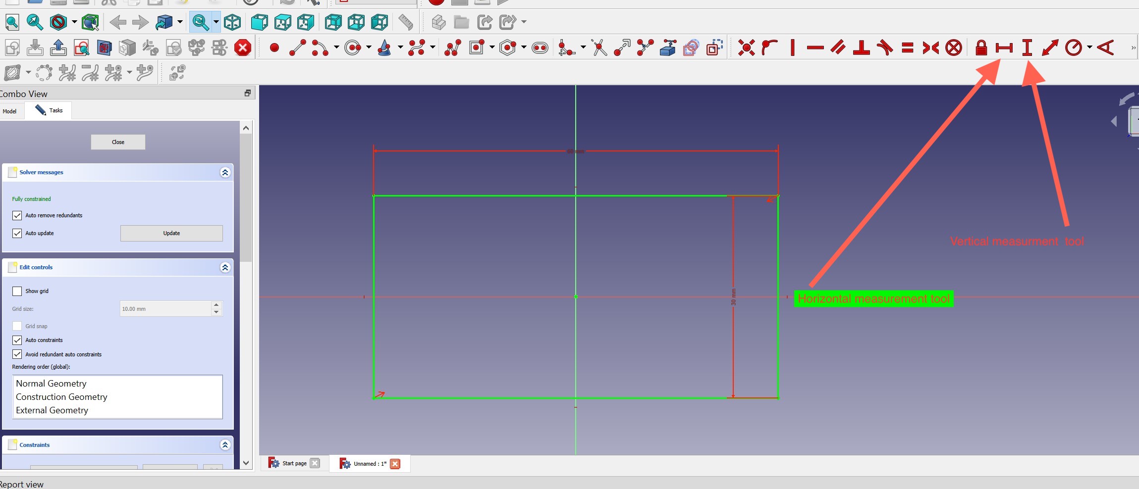
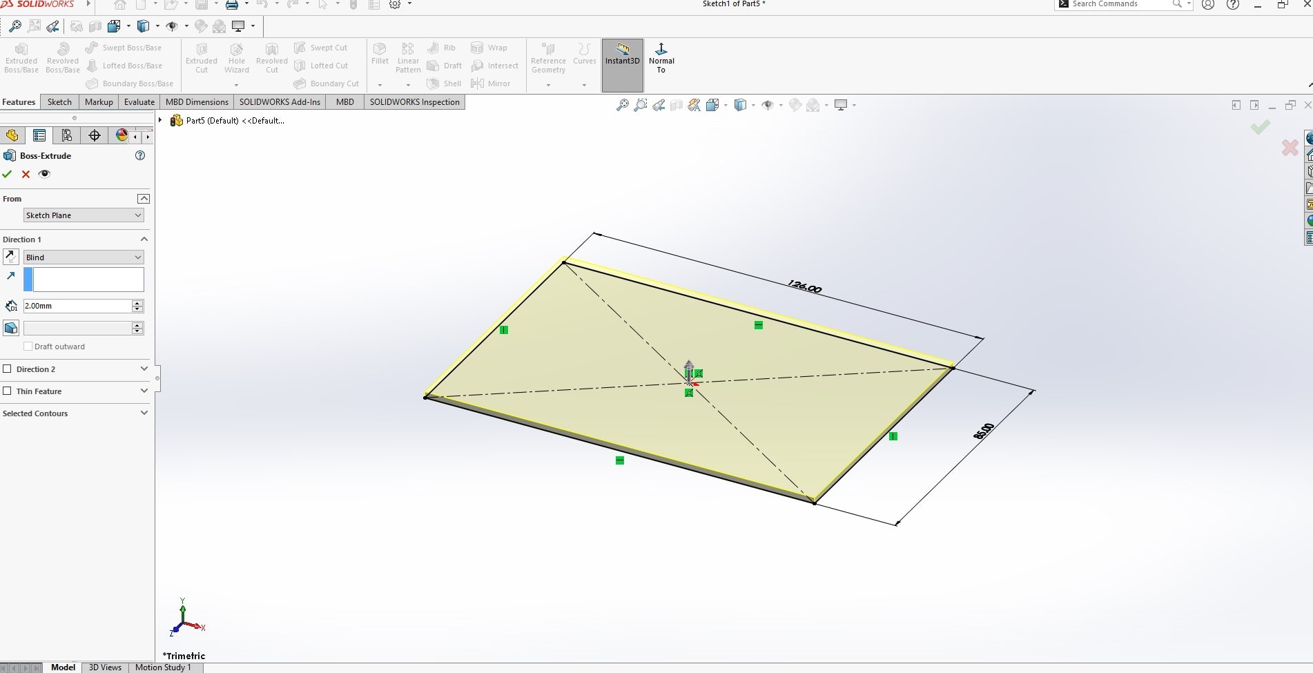
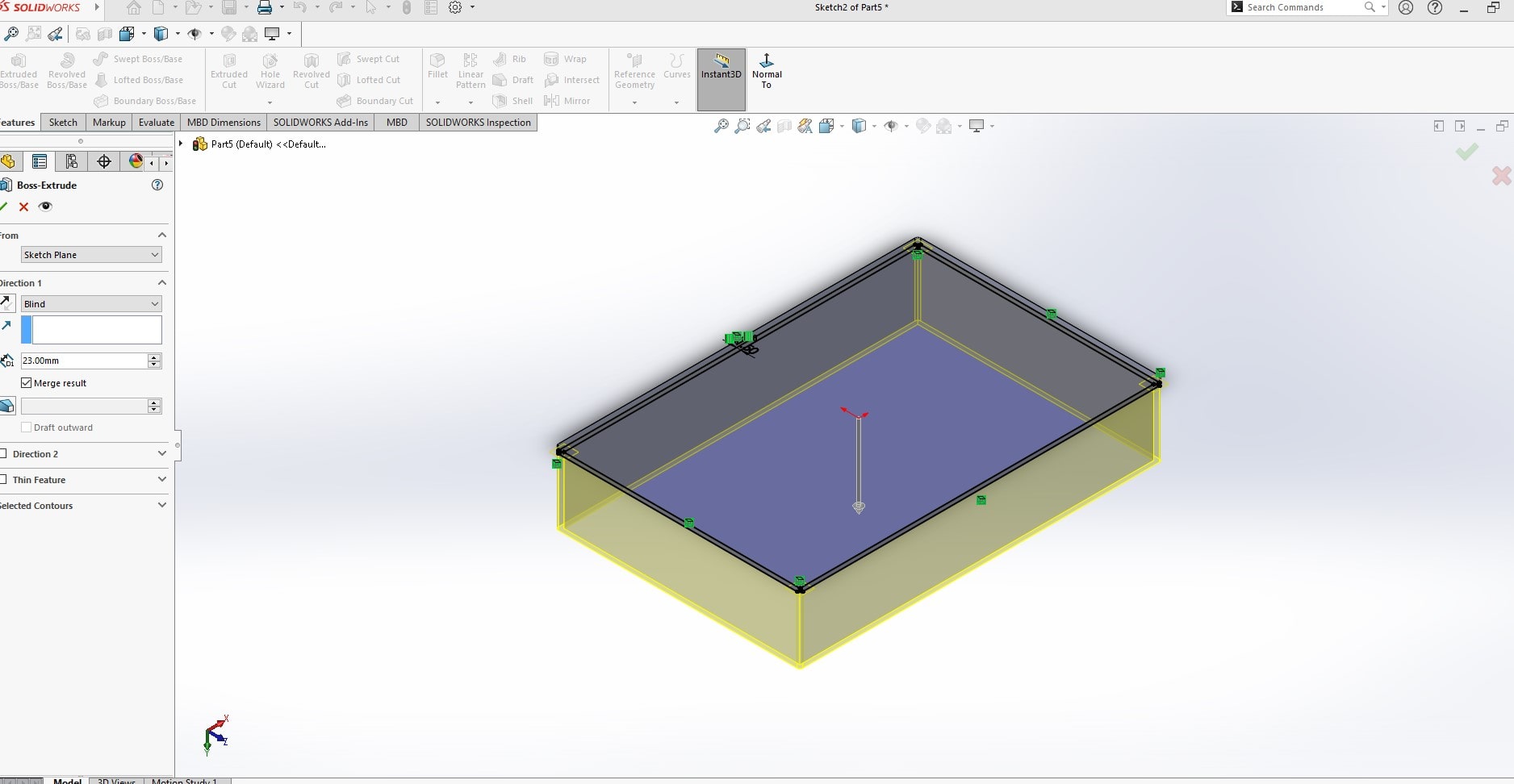
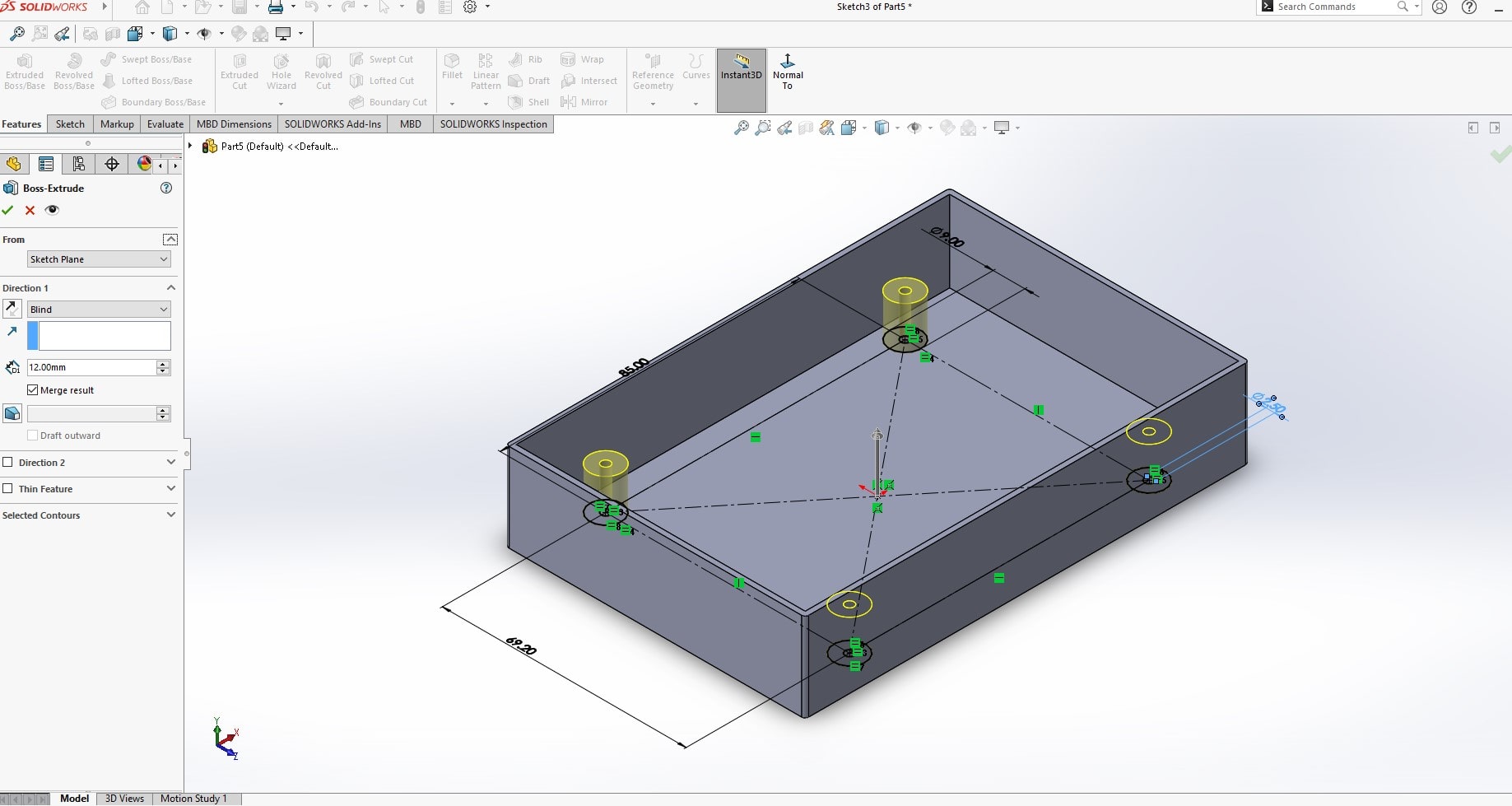
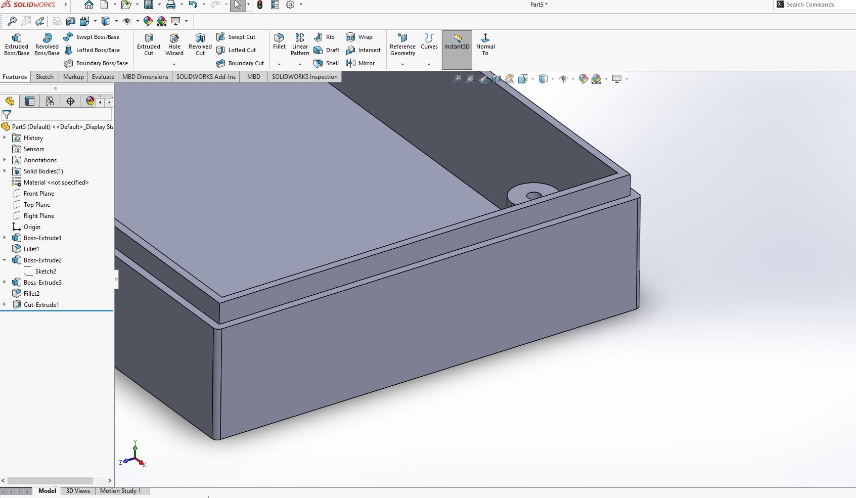
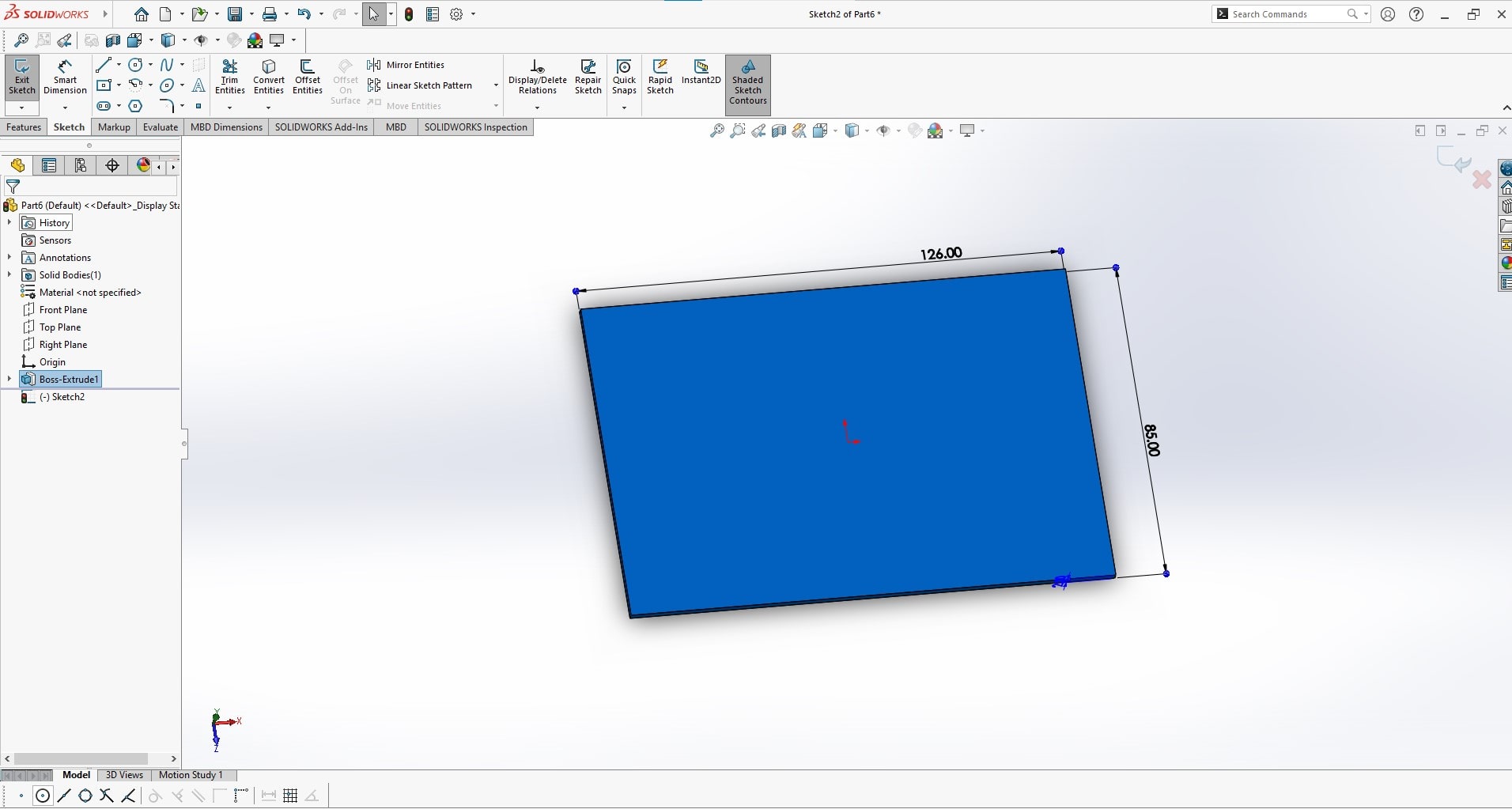
I wanted to draw a rectangular box of 40mm/20mm having 10mm of inside volume . I started with creating the centered rectangular then i use extrude base/boss to create volume
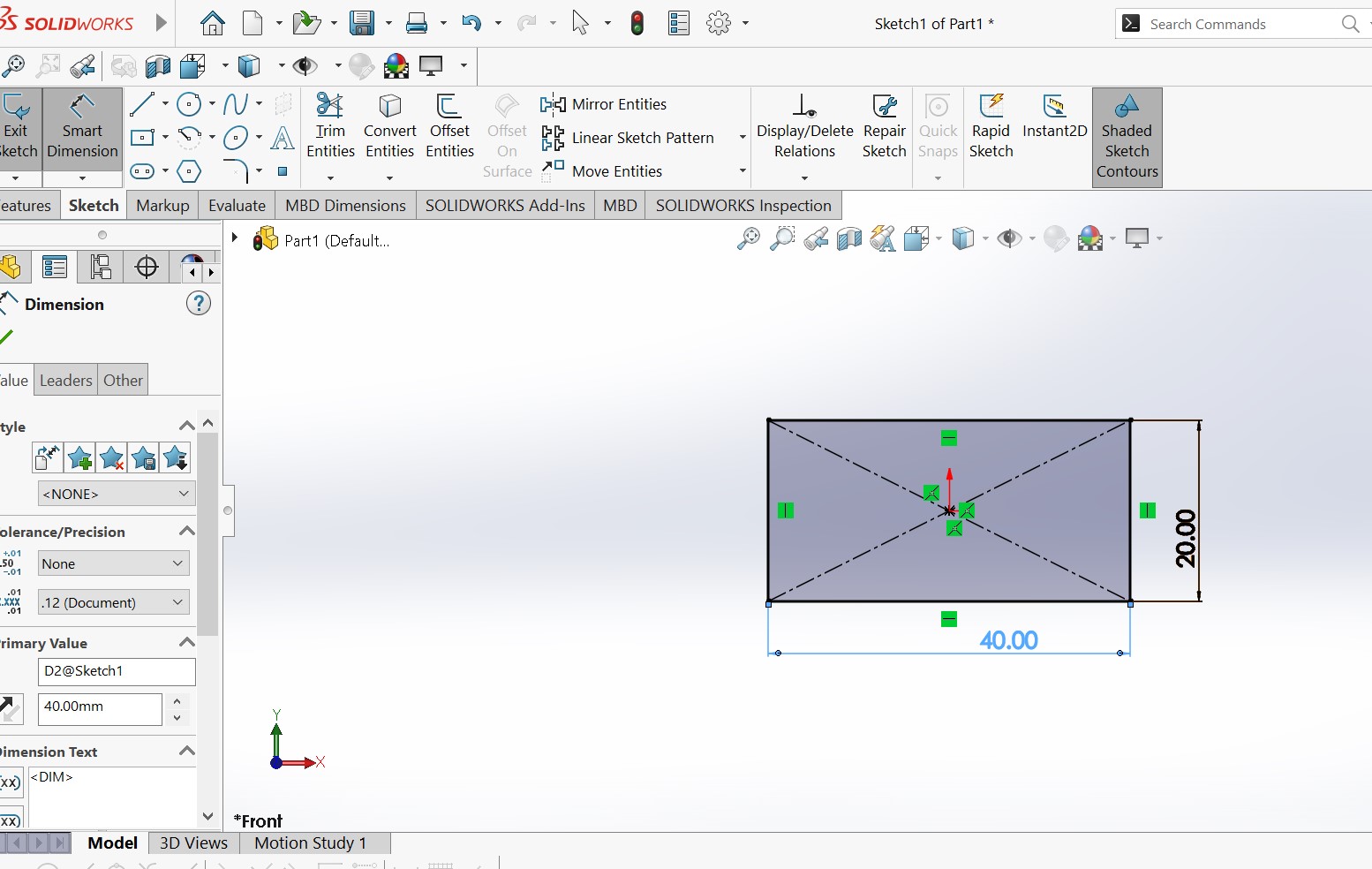
In SolidWorks, an Extruded Boss/Base is a tool used to create 3D solid models by extruding a 2D sketch profile along a specified direction or distance. The tool allows you to create basic shapes such as cylinders, boxes, and prisms, and provides options to control the size, shape, and orientation of the extrusion. The resulting extruded boss or base serves as a building block for creating more complex parts and assemblies.
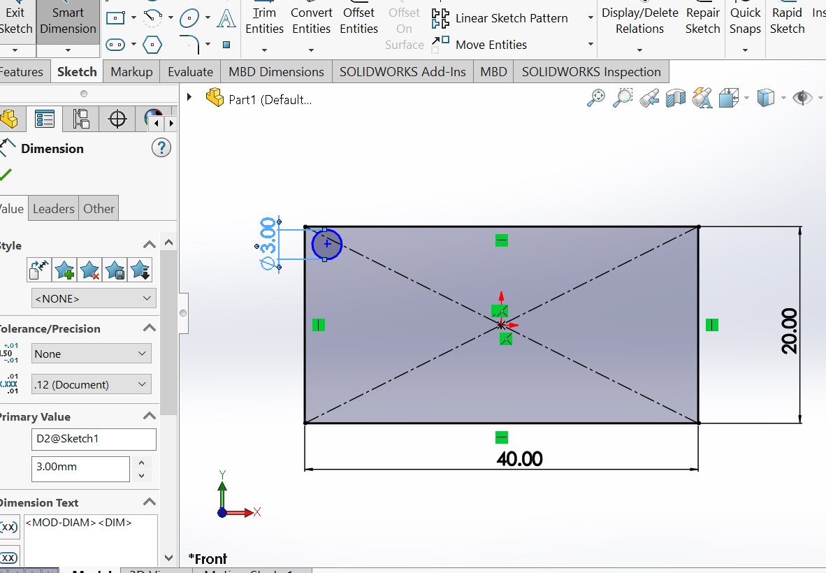
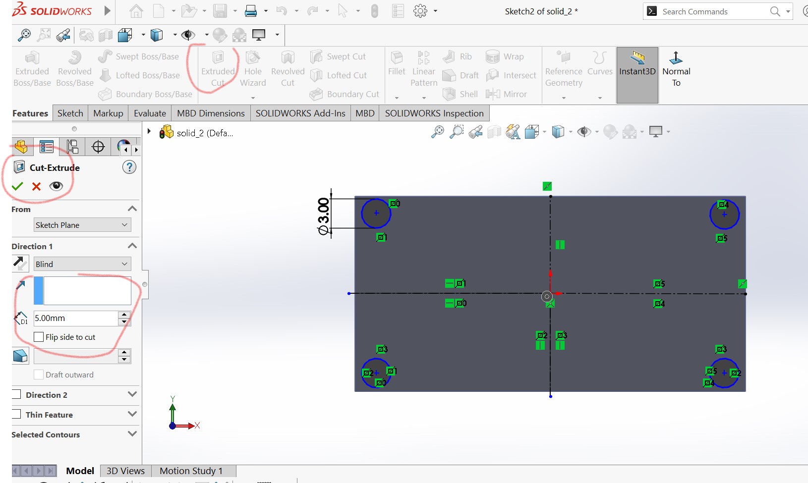
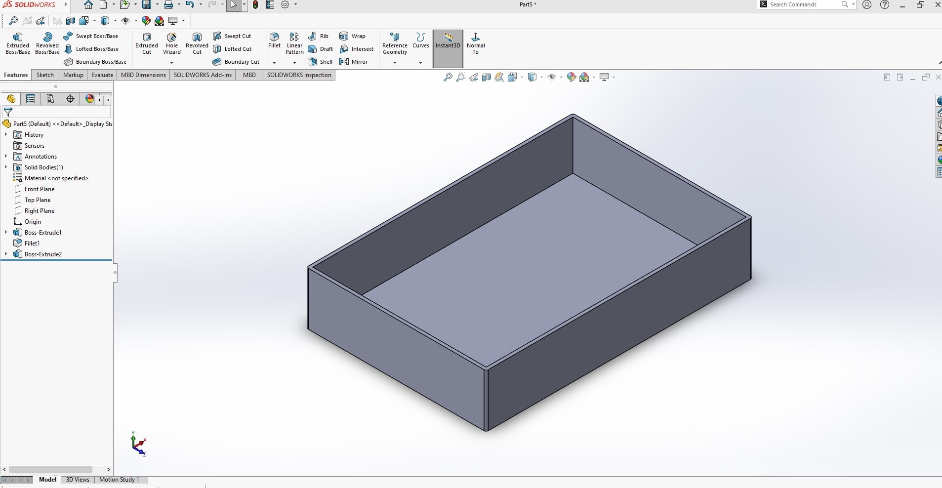
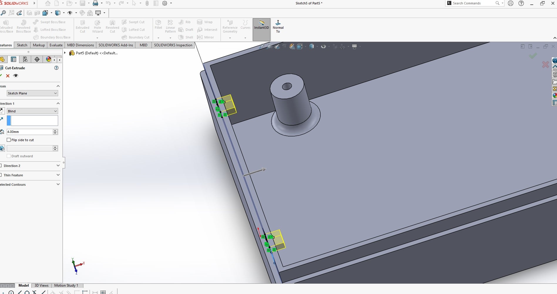
The next step is to make through holes in the solid material aready made
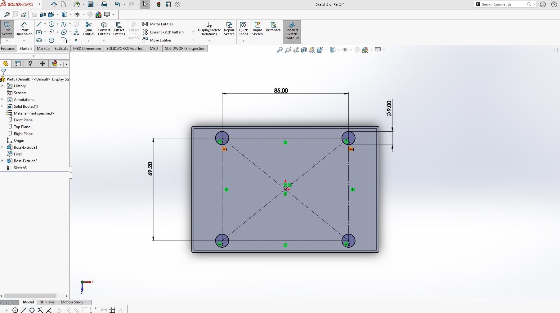
Lets remove those two perpendicular lines in order to draw reference lines . select sketch>trim entities >select trim to closest
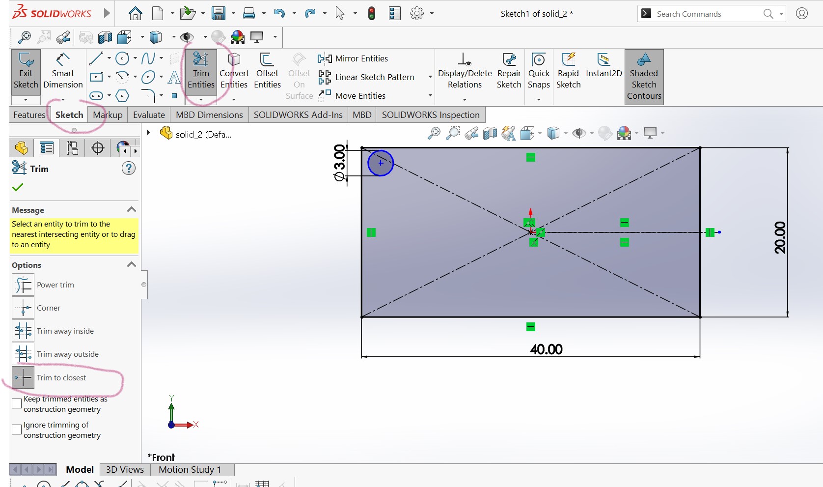
Click on un necessary lines
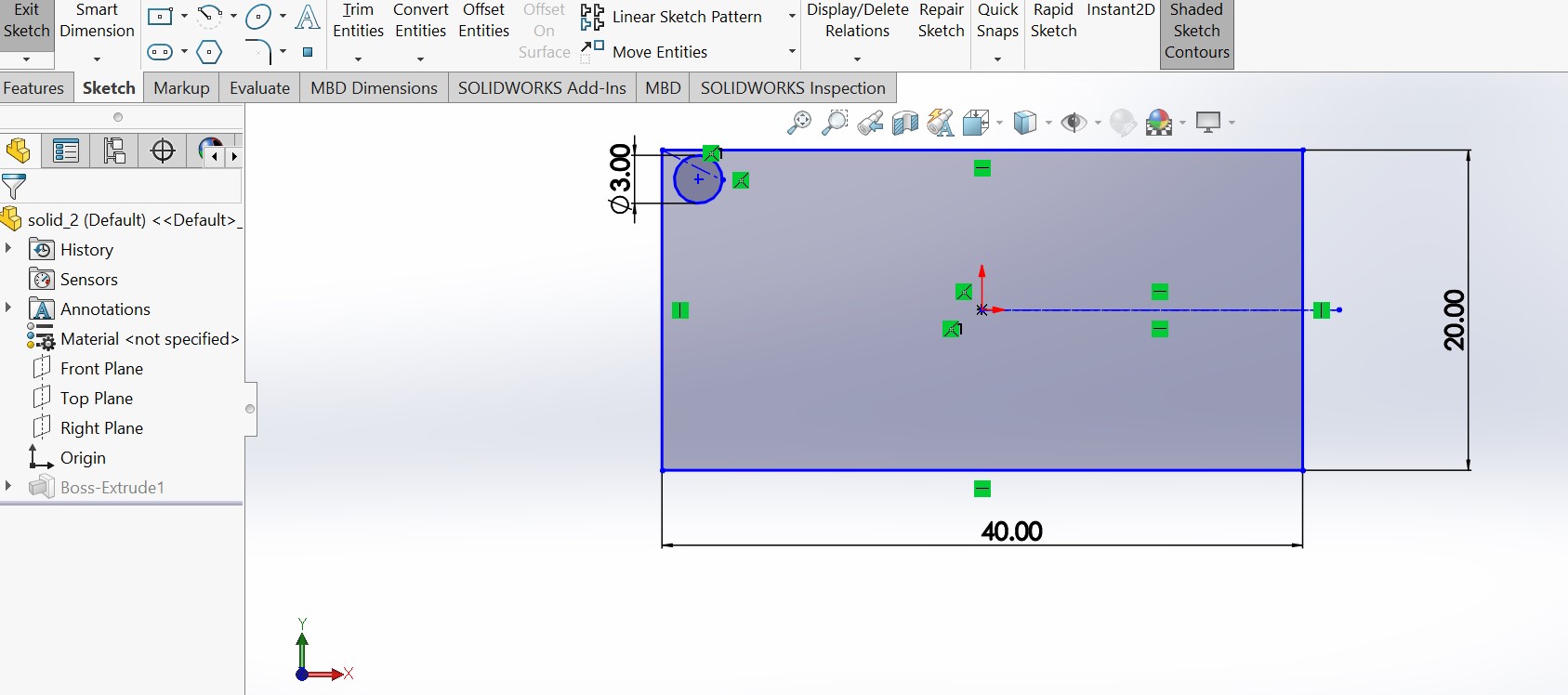
Adding reference lines vertically and horizontally
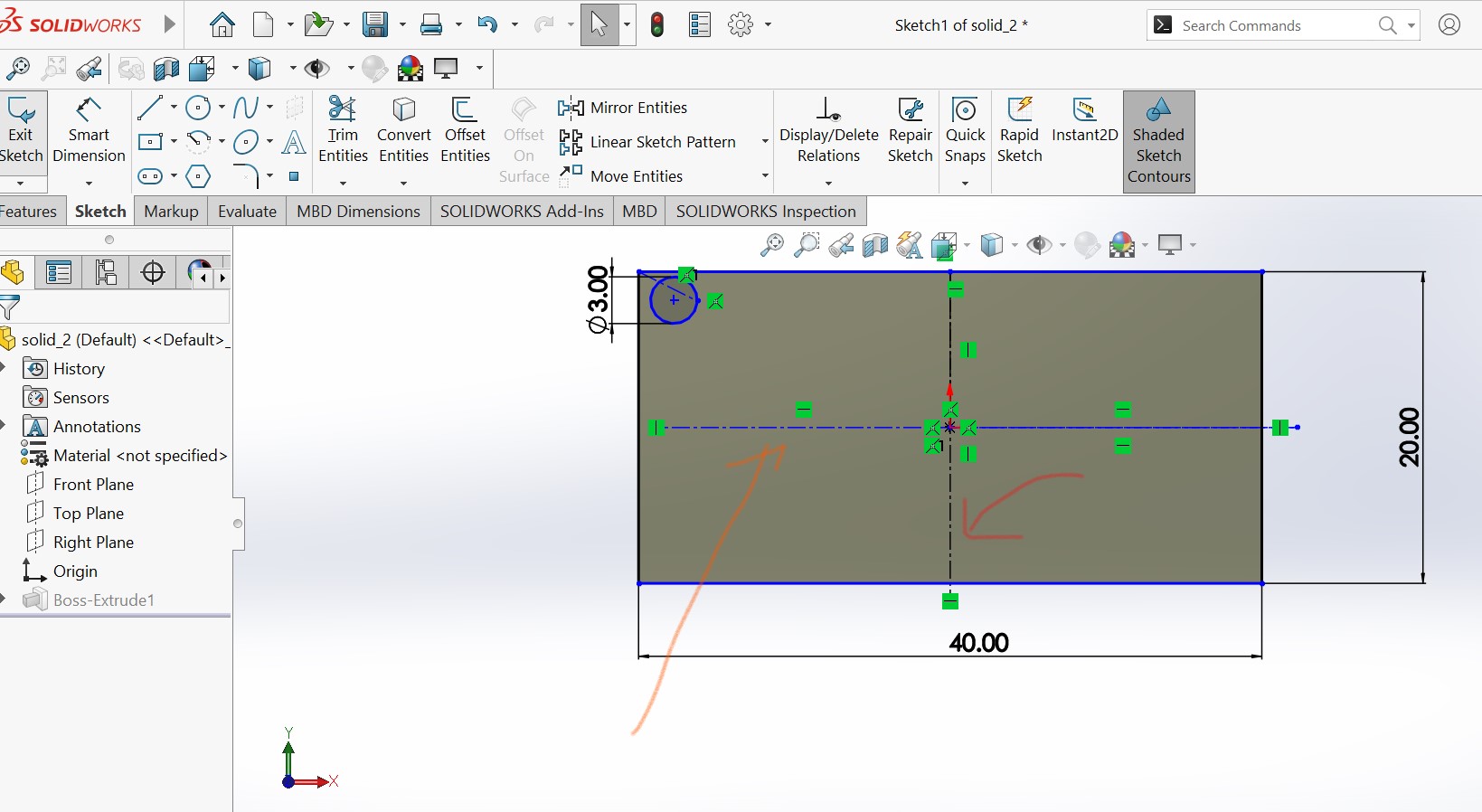
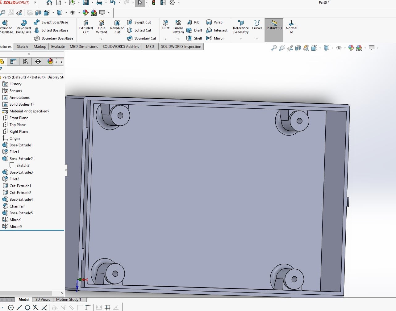
By using mirror entities tool , i can duplicate the 3mm cylce to remaining 3 corners
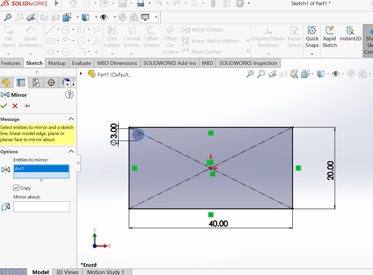
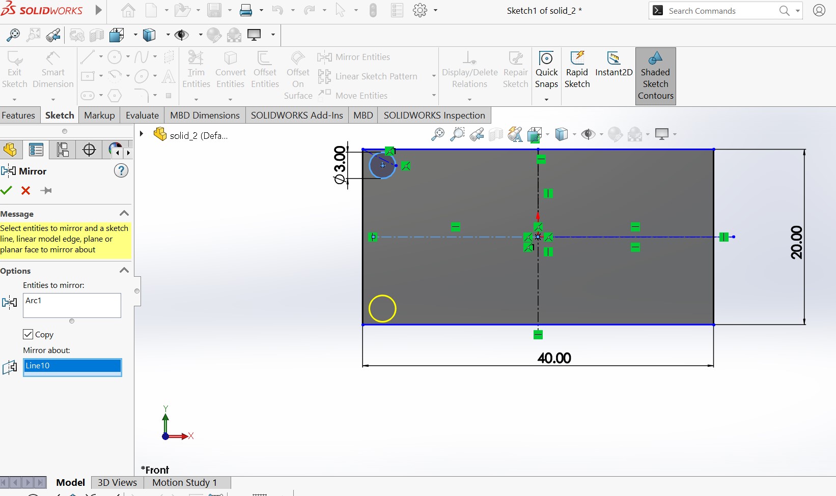
Mirroring all cycle to all corners . you need to redo the same by picking reference line on the side of mirror
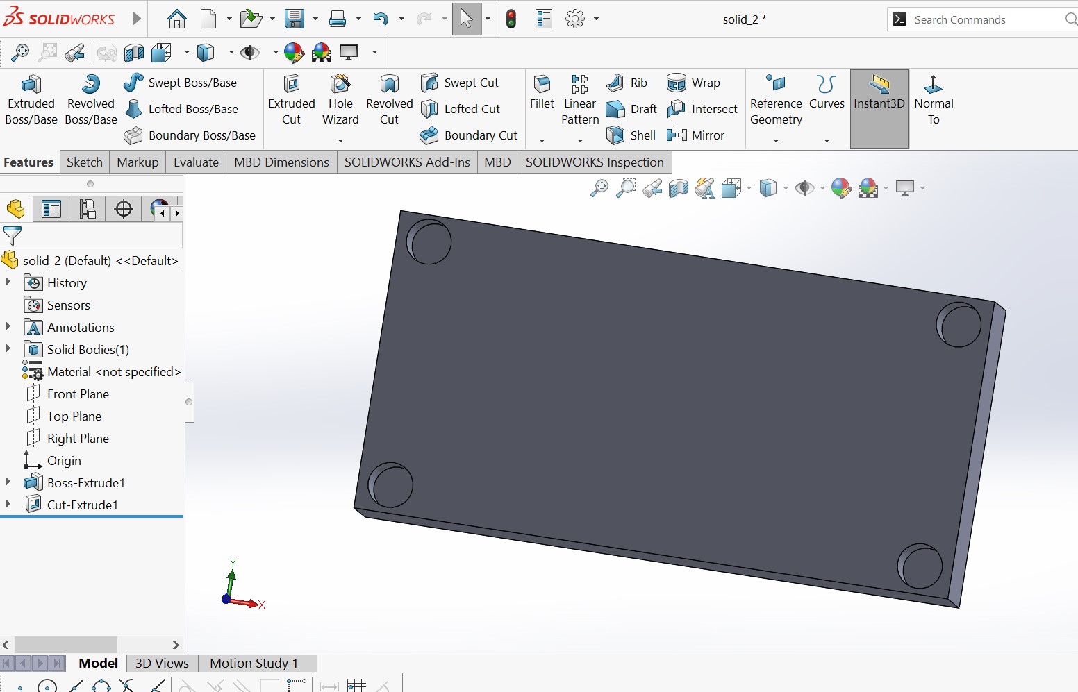
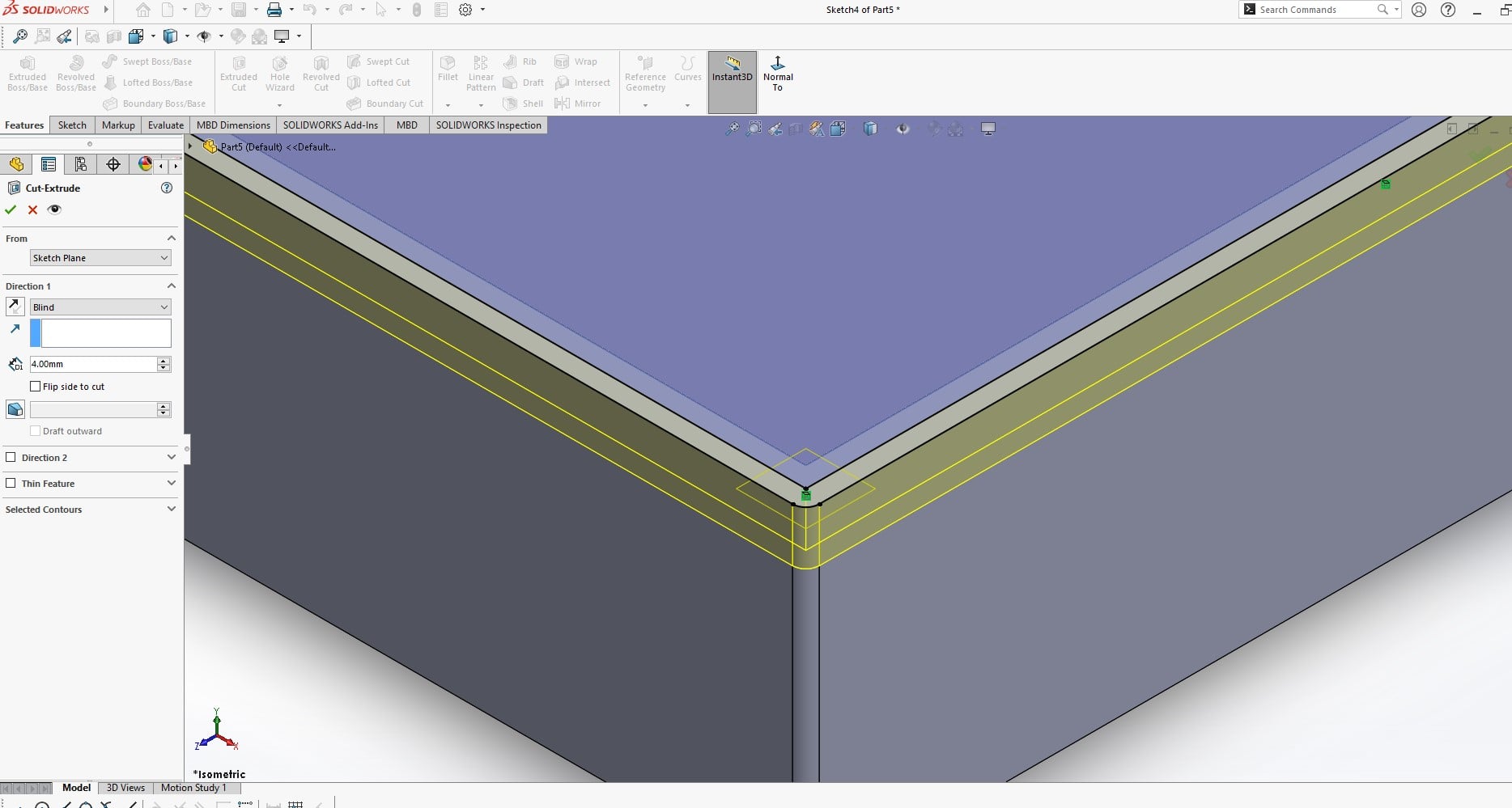
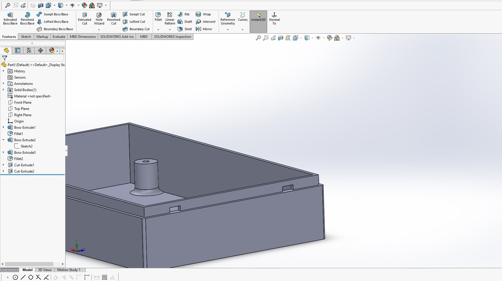
In SolidWorks, an Extruded Cut is a tool used to remove material from an existing 3D solid model by extruding a 2D sketch profile along a specified direction or distance. The tool allows you to create openings, pockets, or hollow spaces in parts, and provides options to control the size, shape, and orientation of the cut. The extruded cut modifies the original solid model, leaving a reduced solid that retains its original shape but with the specified material removed. here i want to create a hole of 5mm in the drawn circles
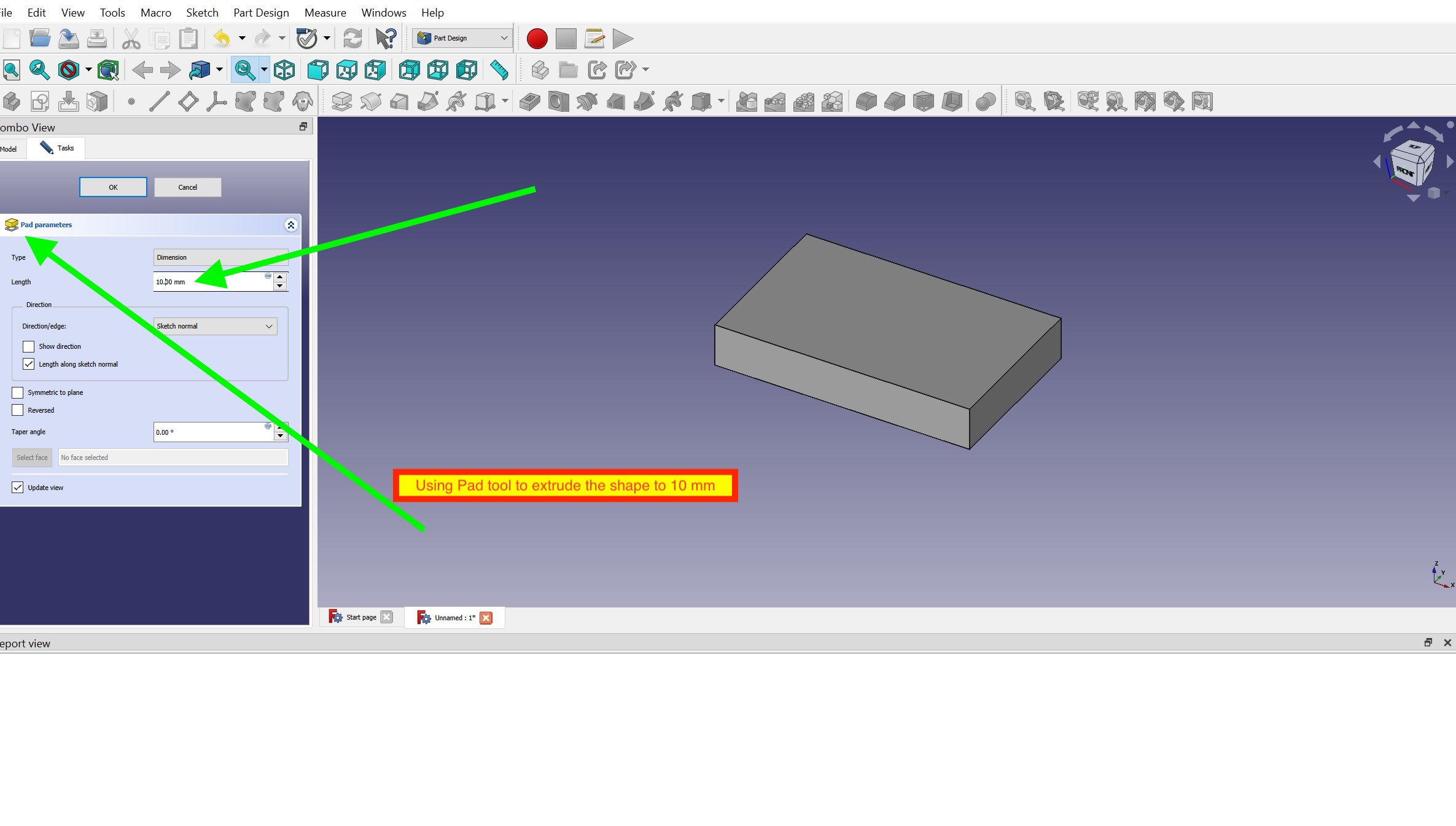
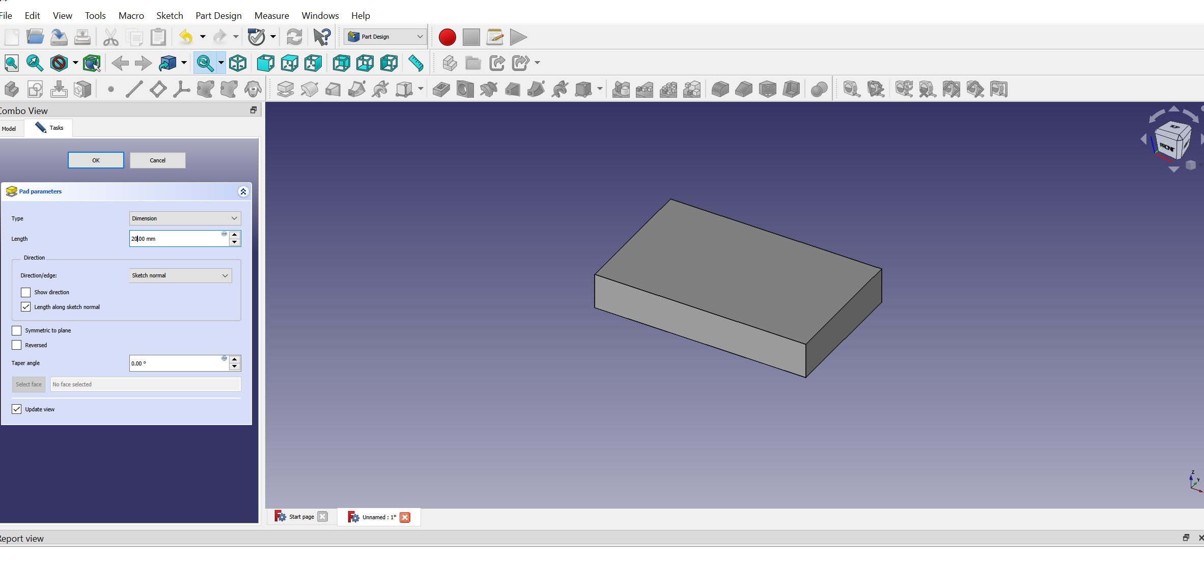
3D Modeling with FREECARD
as a beginner is design , it was also the first tiem to hear freecad. i downlaoded freecard though and insatlled it in my windows pc
I have gone through the following tutorial here which provide a great starting point to start kicad. but it seemed me to be difficult compared with solidworks in terms of usablity and learning curve
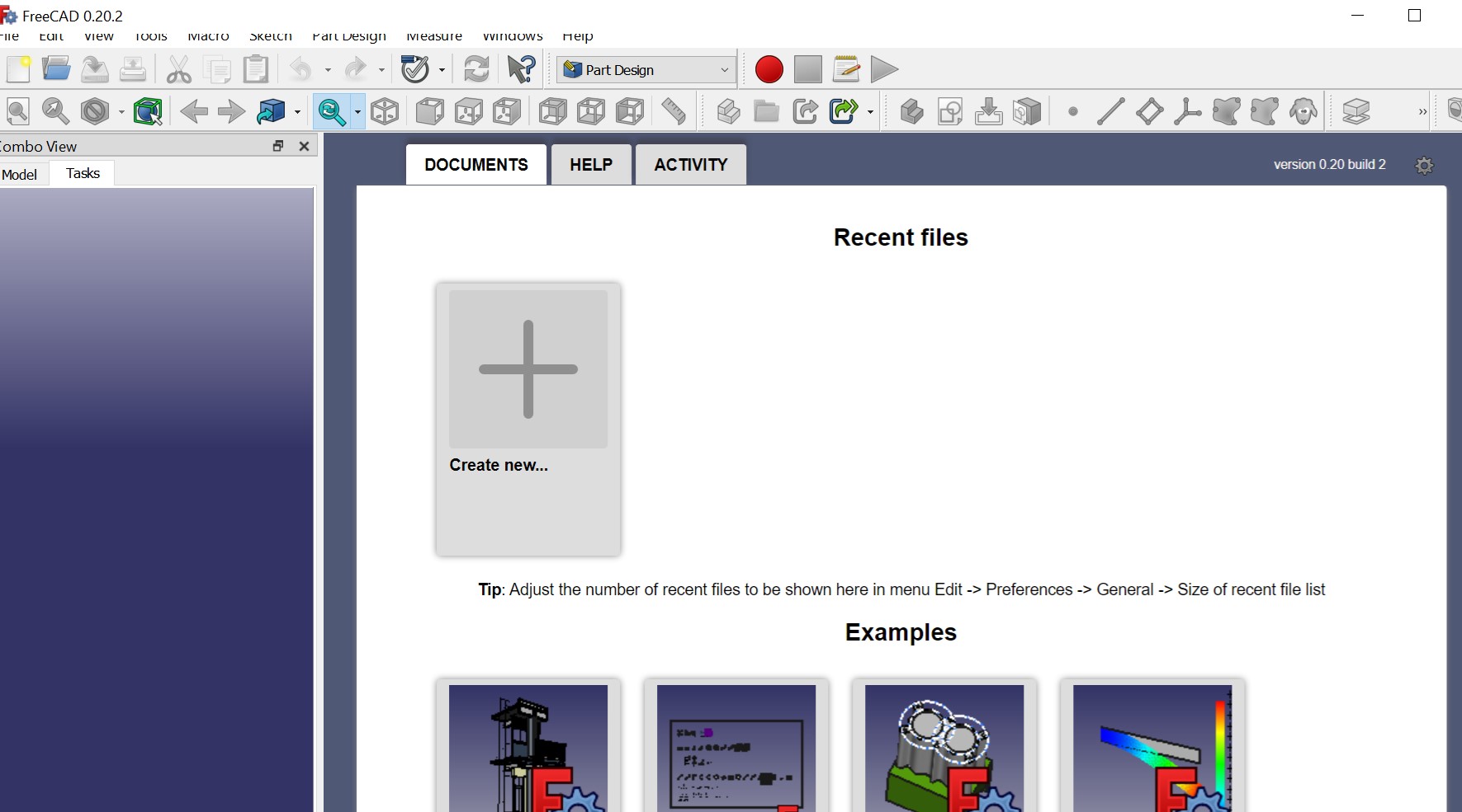
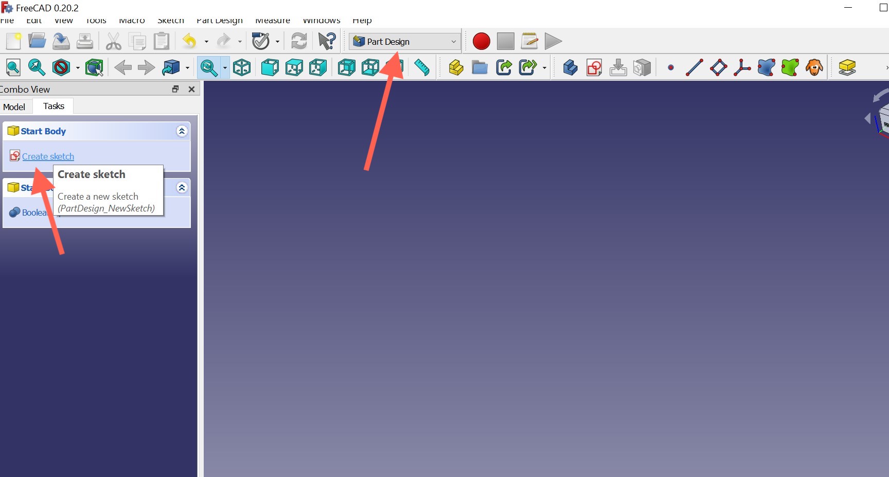
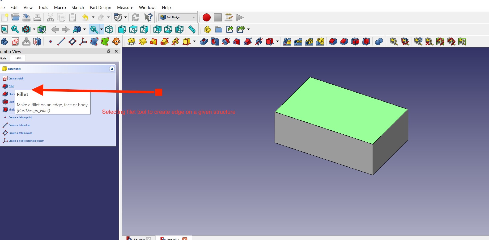
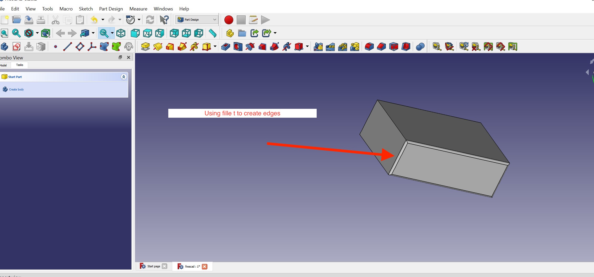
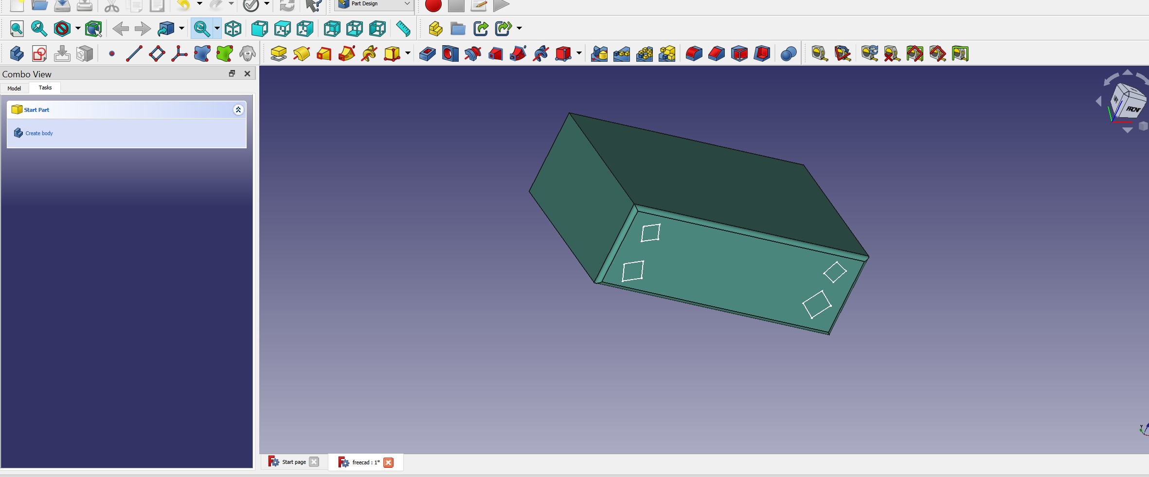
The above documentation is the starting point with freecard and i will improve as i get familiar with it.
Conclusion about use of freecad and solidworks
When we compared the two programs, we discovered that Solidwork was simple to use and learn, but that it was also a paid program that was quite expensive and could only be used by professionals. Beginners should choose FreeCAD because it is free and contains practically all of SolidWorks' capabilities.
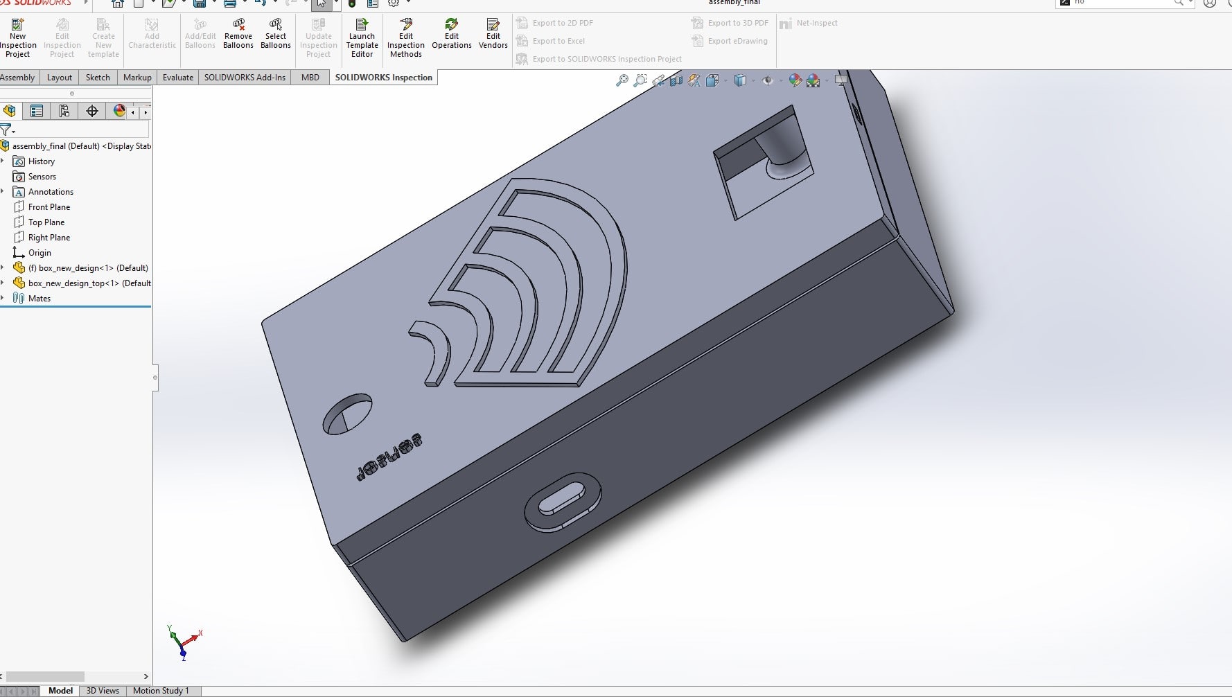
Final Project Cover Box Modeling
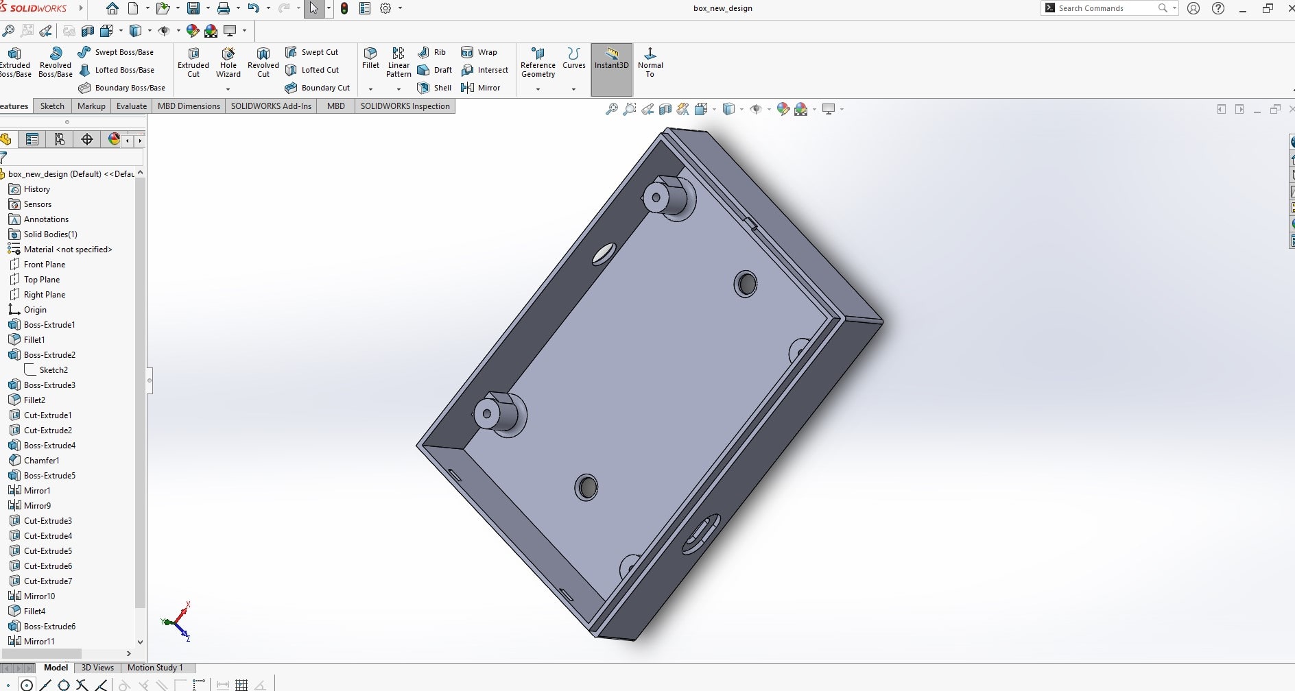
The final project prototype circuit should be placed inside the box enclosure
The purpose of creating an electronic circuit cover box in SolidWorks is to provide physical protection for the electronic components and circuits inside. The cover box serves as a barrier against environmental factors such as dust, moisture, and impacts that can damage the electronics. Additionally, the cover box can also play a role in reducing electromagnetic interference (EMI) and electromagnetic compatibility (EMC) issues, as it can act as a Faraday cage that shields the electronics from external electromagnetic fields.
In SolidWorks, the cover box can be designed with precise dimensions and features such as ventilation holes, snap fits, and screw holes to accommodate the specific requirements of the electronic circuit. This allows for a custom-fit cover box that provides the necessary protection while allowing for easy access to the electronics when needed.
Because of the popularity of solidworks, i prefered to use it in order to be familiar with it and it will be beneficial in my daily task in fablab
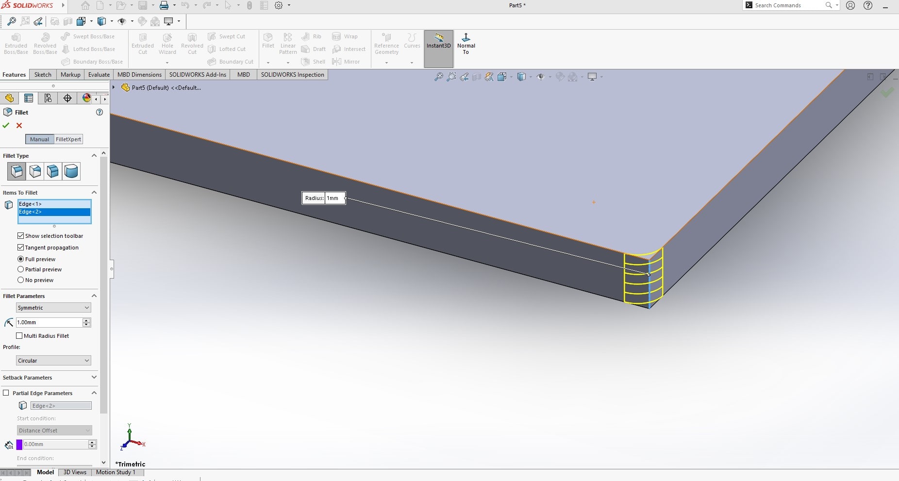
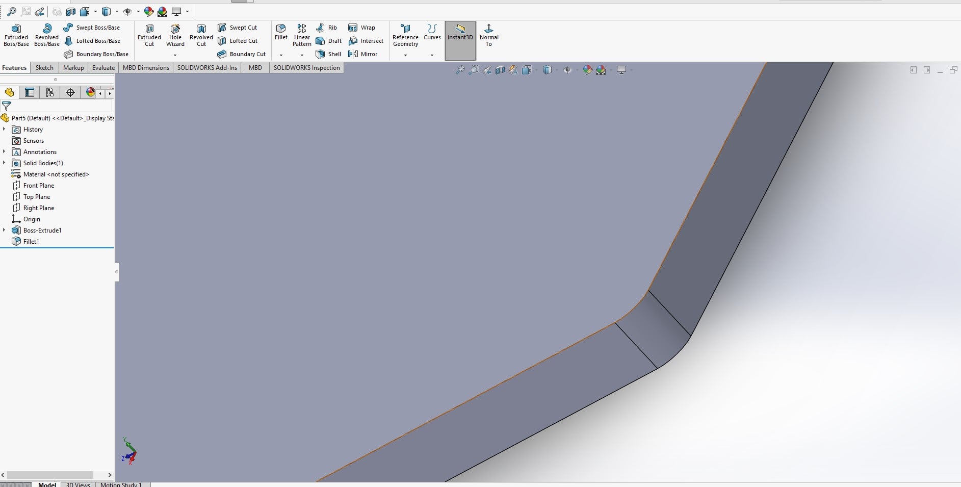
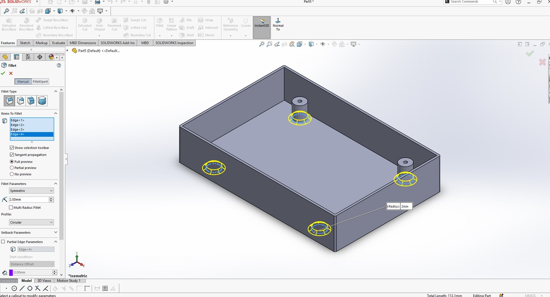
The fillet tool in SolidWorks is used to create rounded edges on parts and models. The fillet tool allows you to add a smooth radius transition between two intersecting surfaces, making the part more aesthetically pleasing and improving its overall design. The fillet tool can be applied to both 2D and 3D models, and it can be used to create fillets of various sizes and shapes. The fillet tool can also improve the functional performance of a part by reducing stress concentrations at sharp corners and i ncreasing its overall strength and durability. By rounding the edges of a part, the fillet tool can also improve its manufacturability, as it eliminates the need for sharp corner transitions that can be difficult to produce with certain manufacturing processes.
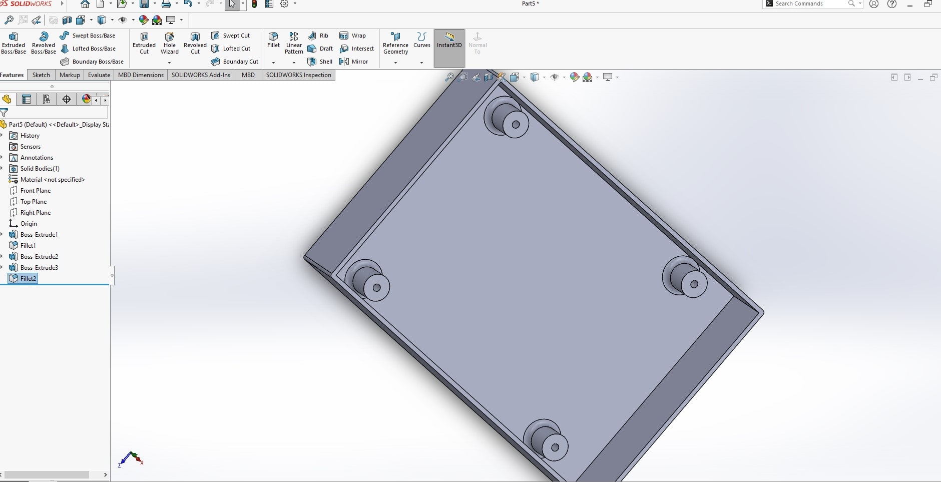
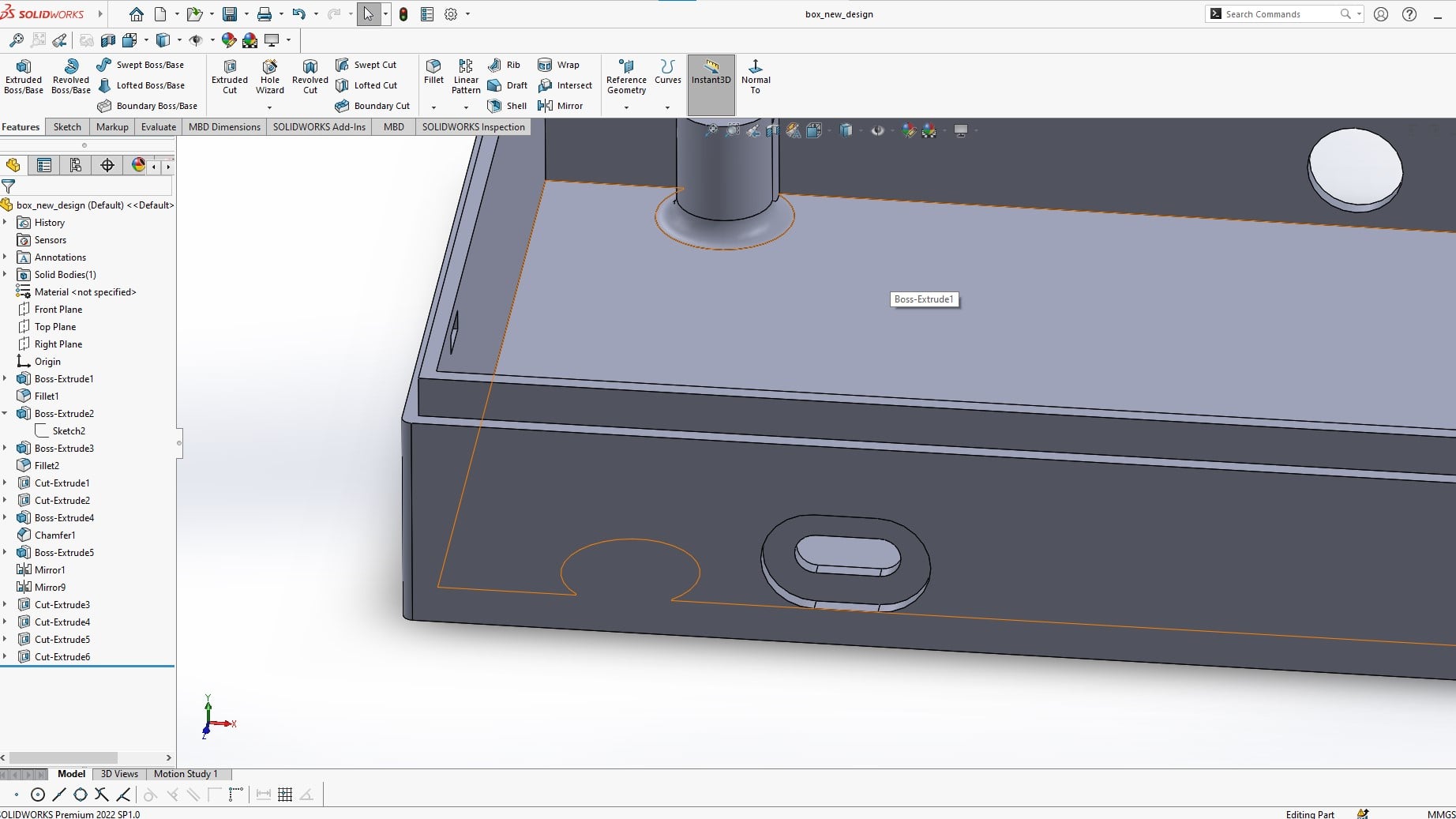
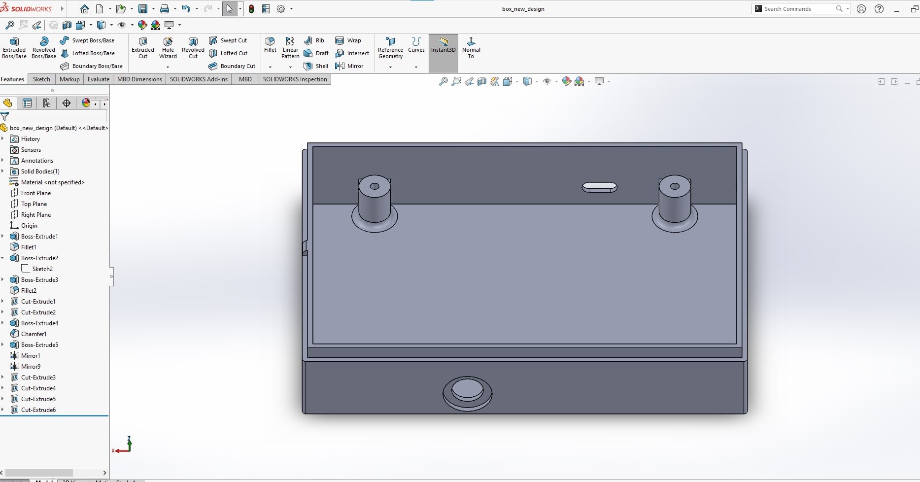

Box base assemly in solidworsk are demonstrated in the following short video
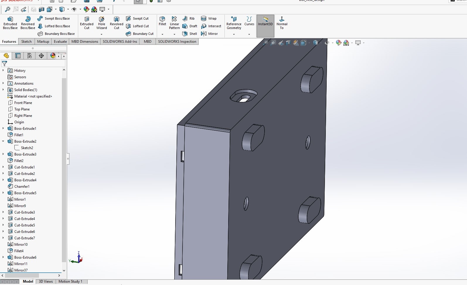
Box and cover assembly
Final project box cover
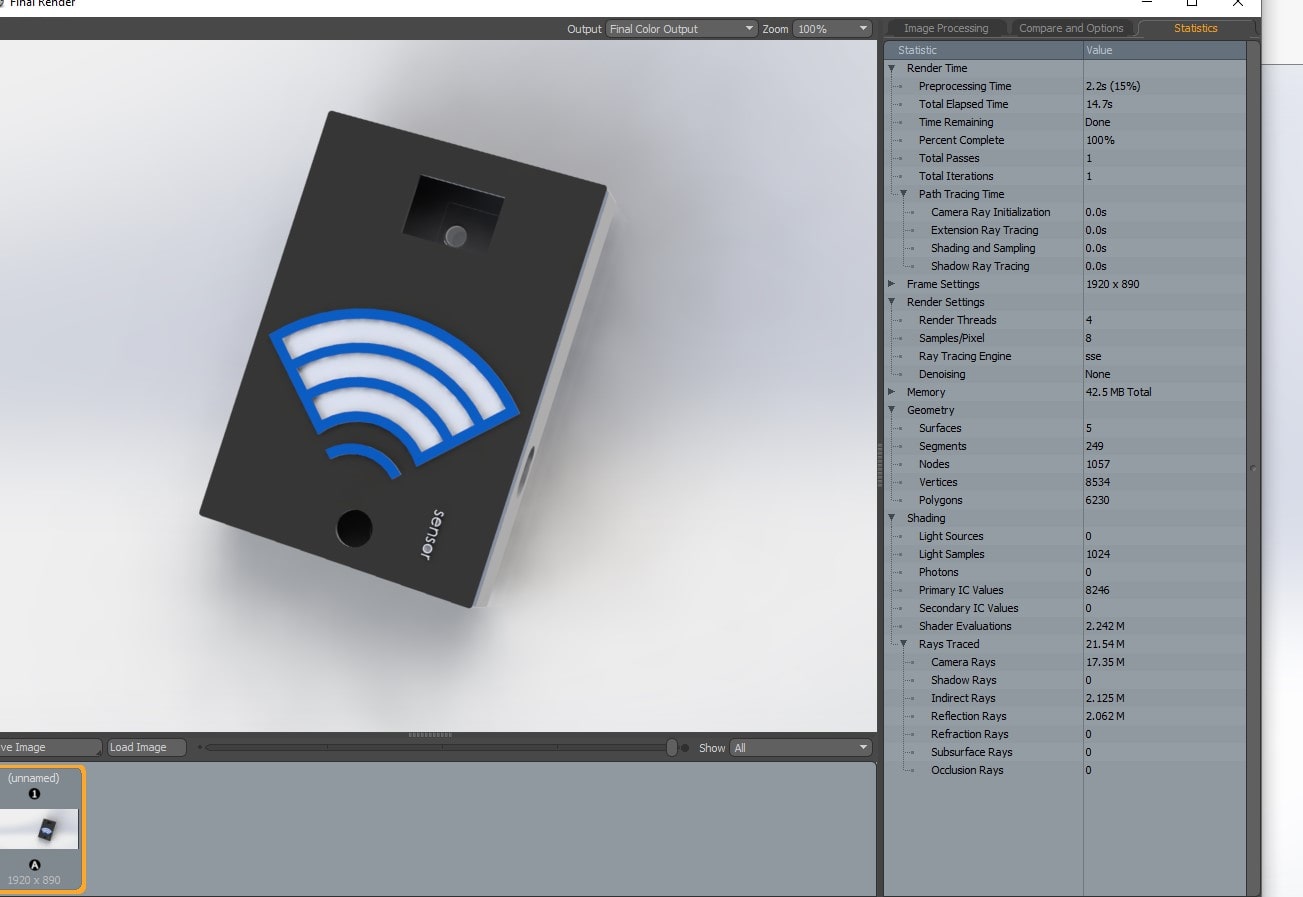
Rendering
rendering!!!!.. i had no idea before about the term rendering. and i used online resources but it was quite diffficult to relate it with my project . finally , my fablab class collegues told me that rendering is the like the generation of high quality image of the things under design
According to this reference , In SolidWorks, rendering refers to the process of generating realistic, photorealistic or near-photorealistic images or animations of 3D models. It involves simulating the way light interacts with materials and surfaces in a scene to create images that look like photographs of real-world objects. The process of rendering typically involves specifying the scene geometry, the lighting and environmental conditions, the materials and textures of the objects in the scene, and the camera parameters. SolidWorks offers various rendering tools, including the PhotoView 360 add-in, which allows users to create high-quality images and animations with advanced lighting, camera, and material options.
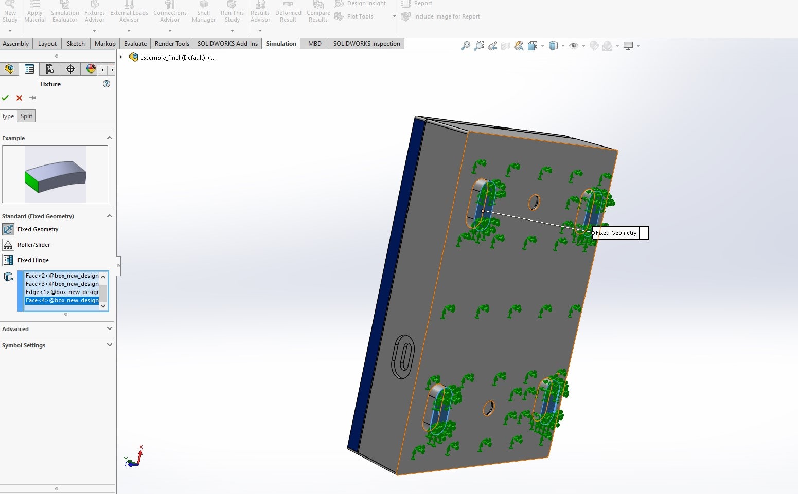
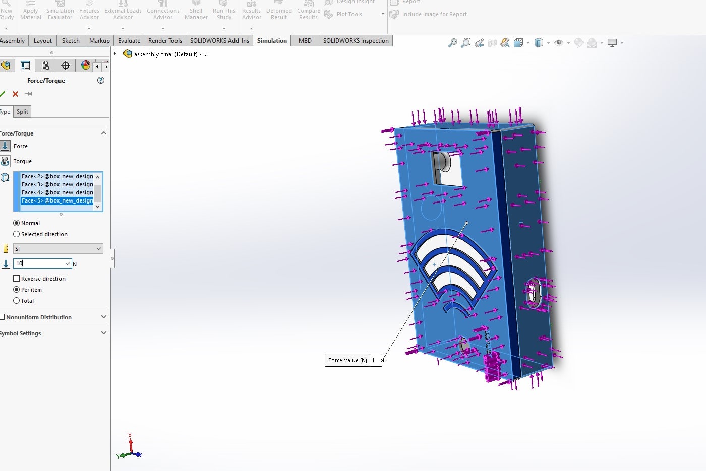
Simulation in Solidworks
Before srating design with design software, i was only aware of simulation of electronics projects. but simulation of physical objects was not in my box of knowlege and i have to make a research on that .
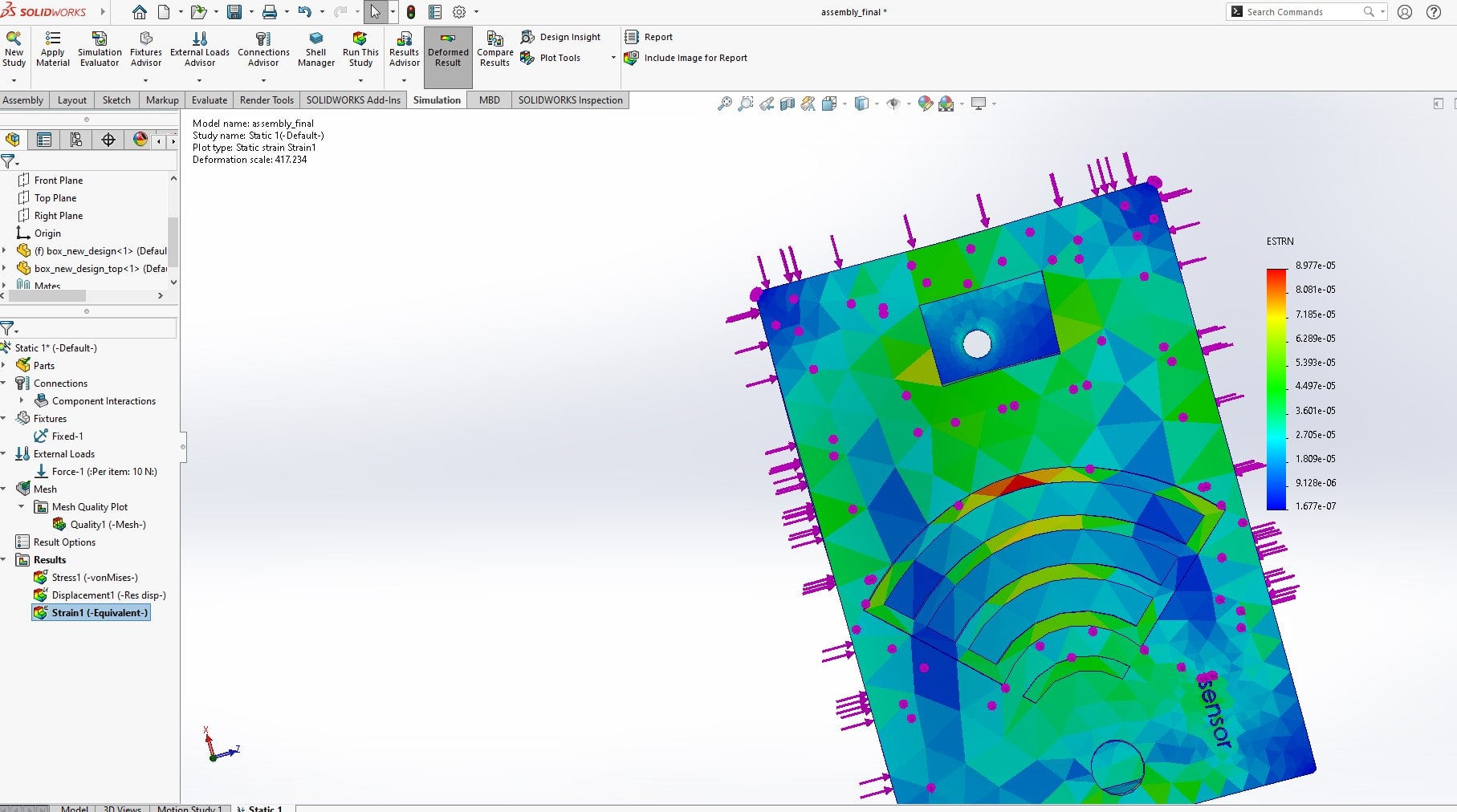
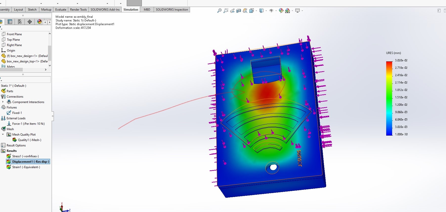
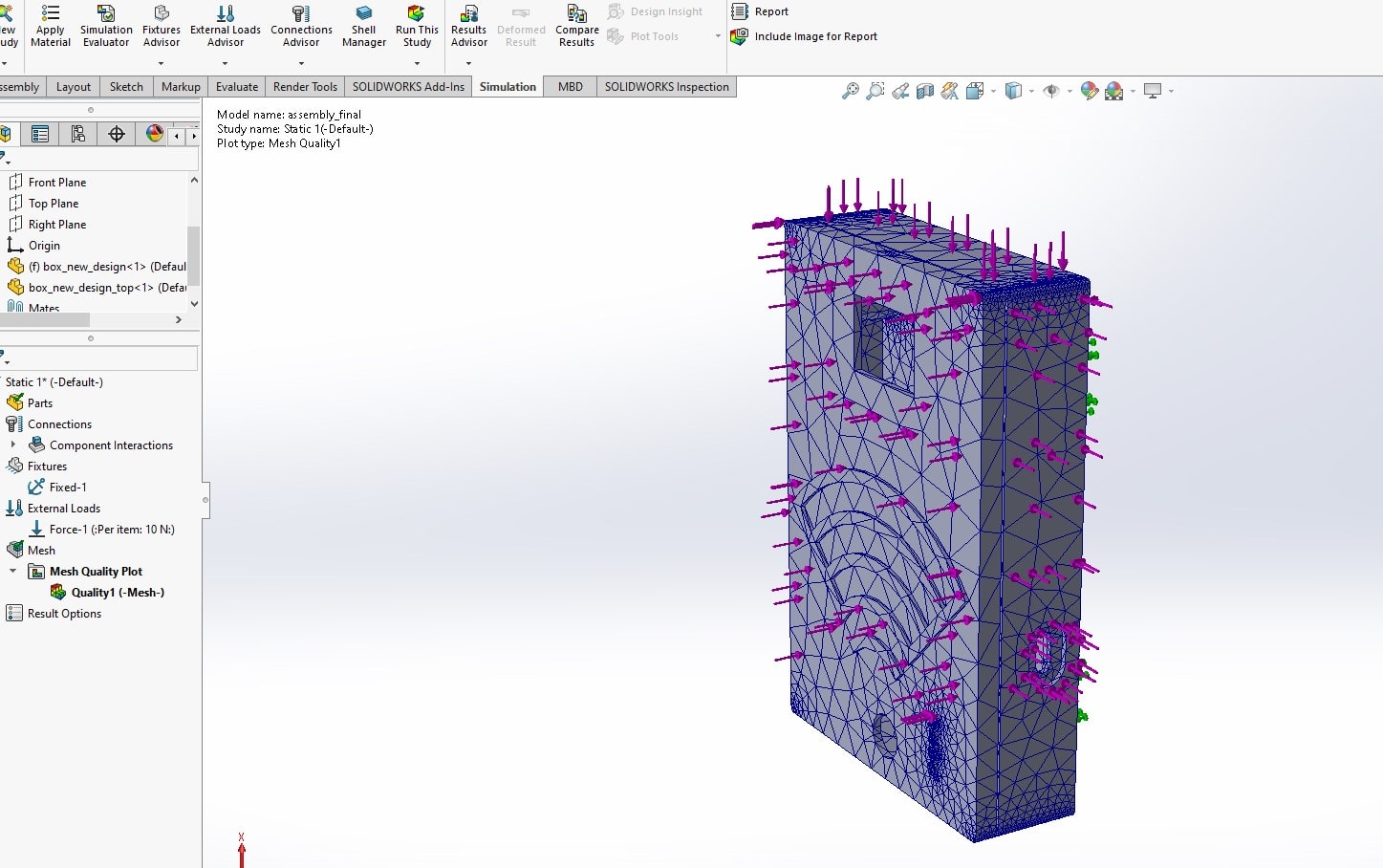
According to Simulation in SolidWorks is the process of analyzing the behavior and performance of a 3D model under different conditions using computer-aided engineering (CAE) tools. It involves using mathematical and physical models to simulate how the model will behave when subjected to different loads, constraints, and other conditions.
Simulation in SolidWorks can be used to evaluate the performance of a product or design, identify potential design flaws or weaknesses, optimize product performance, and reduce development costs by minimizing the need for physical prototypes. By simulating the behavior of a product under different conditions, engineers and designers can gain valuable insights into how the product will perform in the real world and make informed decisions about design changes and improvements.
Challenges Faced
The big challenges i faced are associated with solidworks
As a first-time learner of SolidWorks, I've faced a few challenges that I'd like to explain them in simple terms:
- Understanding the Interface: One of the main challenges I faced when I first started using SolidWorks was understanding the interface. There are many icons, buttons, and menus to navigate, and it can be overwhelming for a beginner. However, with some practice and guidance, I was able to get familiar with the interface and use it effectively.
- Learning the Terminology: SolidWorks has its own set of terminology, which can be confusing for a first-time learner. I had to learn what terms like "extrude," "sweep," and "fillet" meant, and how to use them in my designs. Once I got the hang of it, it became easier to understand.
- Creating Sketches: Creating sketches is an essential part of using SolidWorks, but it can be challenging for a beginner. I had to learn how to create sketches using lines, circles, and other shapes, and then use those sketches to create 3D models. It took some time and practice, but I eventually got the hang of it.
- Understanding Design Intent: Design intent is the idea behind a particular design. It can be challenging to understand, especially when I was first starting. I had to learn how to think about the end product and how it would be used in order to create a design that would work well.
- Troubleshooting: Finally, when I first started using SolidWorks, I encountered many errors and issues that I didn't know how to fix. It was frustrating, but with the help of tutorials and forums, I was able to learn how to troubleshoot and fix these issues.
Overall, learning SolidWorks was a challenging but rewarding experience. I had to be patient, ask questions, and practice regularly in order to improve