SMART ACCESS CONTROL SYSTEM
FINAL PROJECT WORK ORGANIZATION
- Project Description
- High Level Design of the Project
- List of Materials/ components needed
- Mechanical Design
- Electronics Production of PCB and soldering
- Interfacing with Sensors and Actuators
- 3D Design of the Enclosure/Cover
- Server/Backend Side development
- Front-End development
- Full System Integration
- Final Results and Video
- firmware, Backend and frontend Git Repo
- Downlaod Design files here
- Project Licence Agreement
Project Description
Project Name: SMART ACCESS CONTROL SYSTEM
What does it do?
Providing access or denying access to a given facility after Automatic temperature check
What are the beneficiaries ?
- Office building
- School
- Hospital
- Higly Secured building like banks etc....
Ratinale
The COVID-19 pandemic has created a need for effective measures to screen individuals for fever, which is one of the common symptoms of the disease. Traditional thermometers, such as mercury thermometers, can be unreliable and are not suitable for use in public places. Additionally, manual temperature screening is time-consuming and can lead to long lines and delays. There is also a need to keep track of individuals who have been denied access due to a high temperature.
Advantages
- Accurate and reliable temperature measurement: The infrared thermometer based on the MLX90614 sensor can accurately measure body temperature from a distance, reducing the risk of contamination.
- Non-contact measurement: The device measures temperature without contact, reducing the risk of cross-contamination.
- Quick and easy to use: The device is easy to use and can be operated by anyone, making it suitable for use in public places.
- RFID integration: The device also includes an MFRC522 RFID reader to read the RFID tags of authorized personnel, so that only authorized personnel can access the facility.
- Automated access control: The device automates the process of temperature screening, reducing the need for manual screening, and reducing the risk of human error.
- Remote monitoring: The microcontroller sends user data to a web app via internet, which can be used to keep track of suspected individuals and monitor the spread of the disease.
what did you design?
- Electronic circuit
- PCB Design
- PCB Milling
- 3D Design of Cover
- 3D Printing
- Software(backend and frontenf)
- Embedded software..
Materials Used and related cost
The materials can be found here
What processes Used
Project Sketching
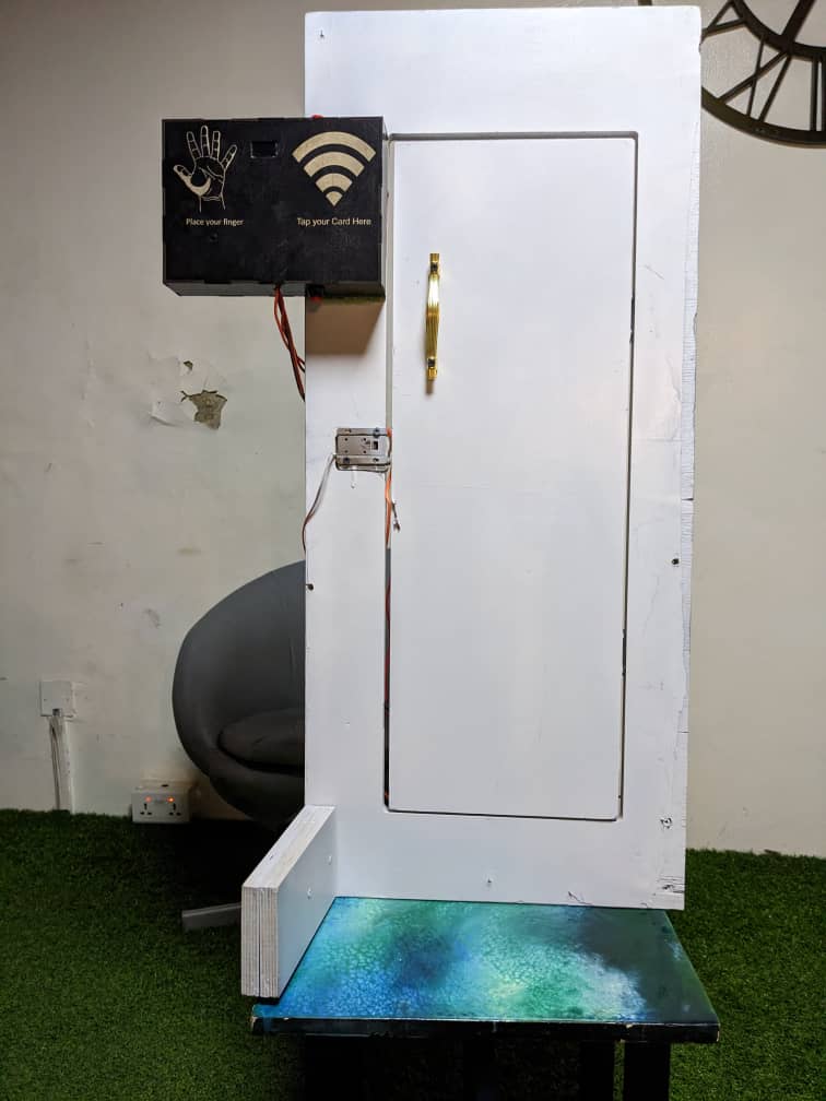
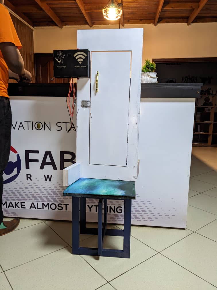
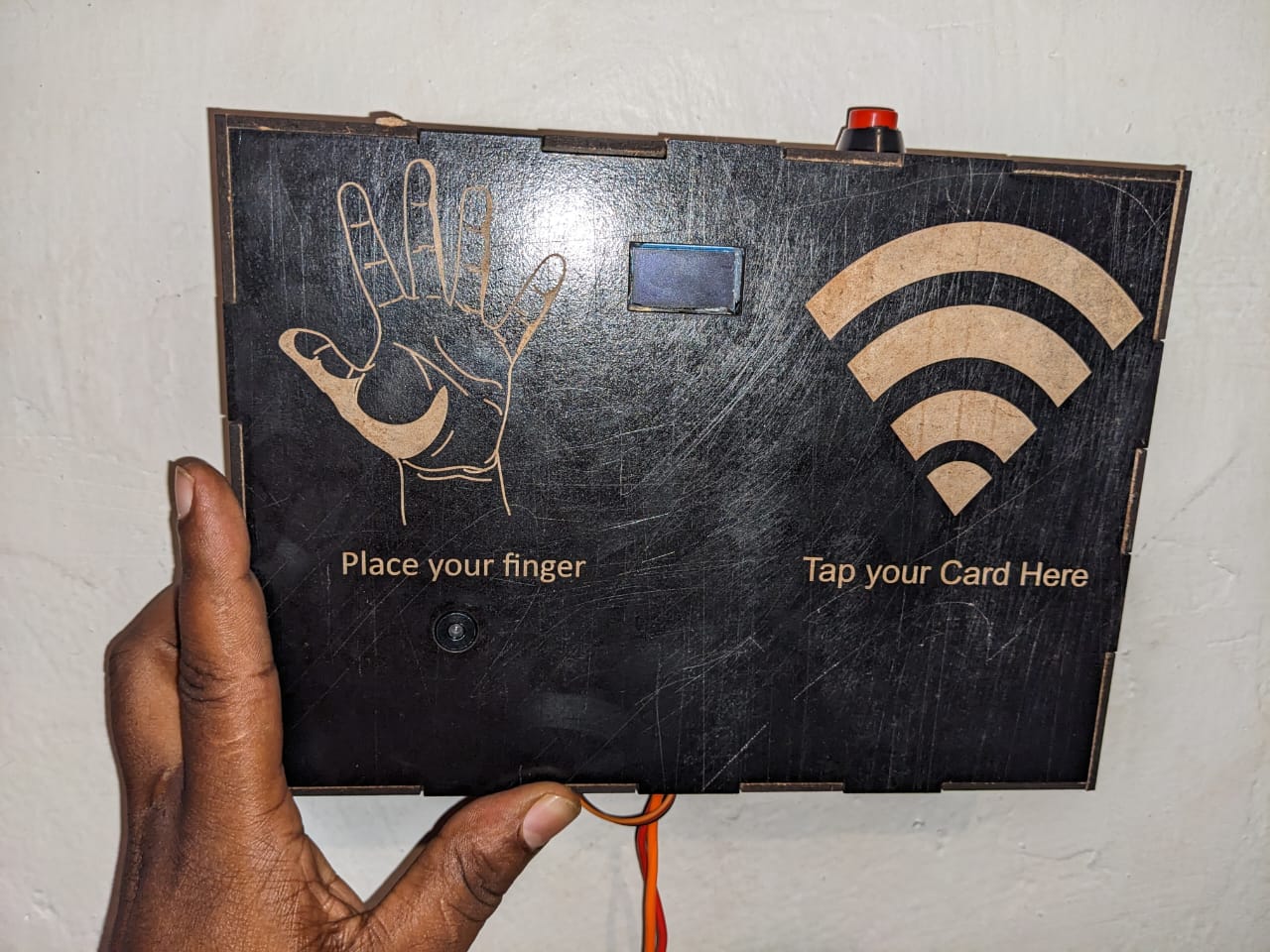
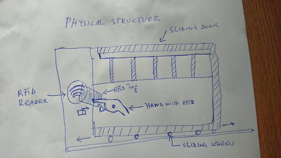
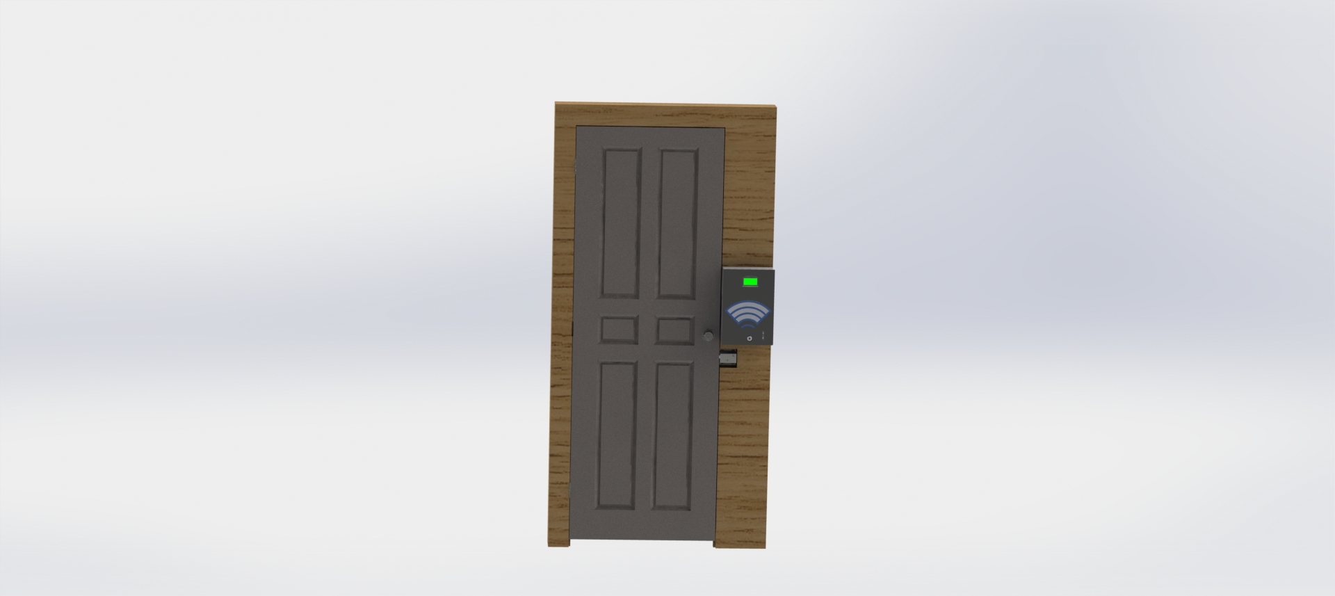
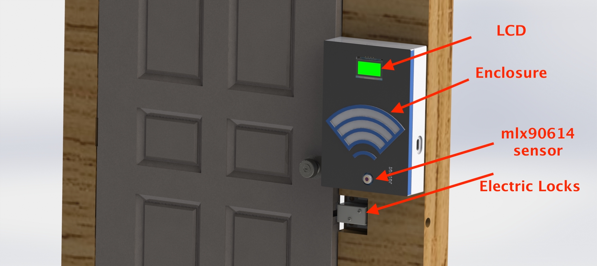
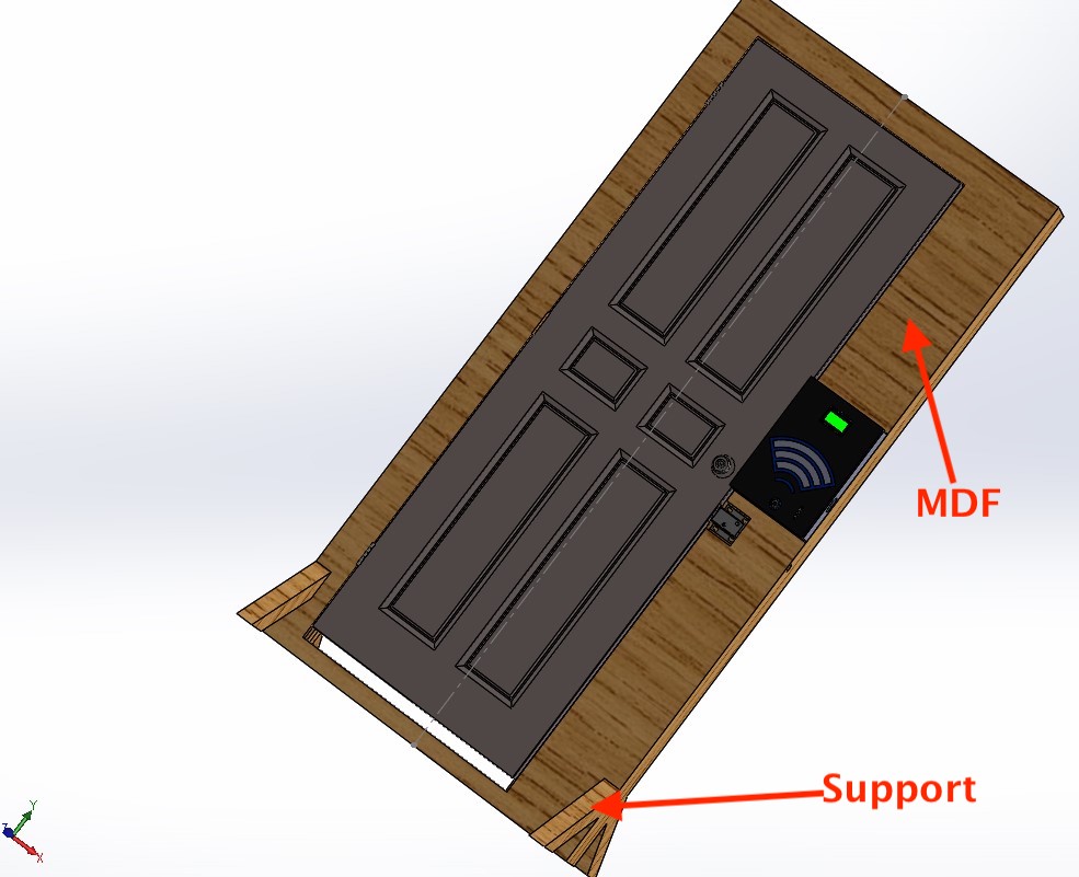
The following pictures illustartes the physcal layout ogf the system where by a sliding gate has an RRFID reader where user taps his tag in order to get access to the facility. if the user is known, his temperature is recorded. if the temperatureis in normal range, he is granted access and if his out of normal range, the access is automaticaly denied and alert is sent to competent organ in case of covid-19 prevention
software
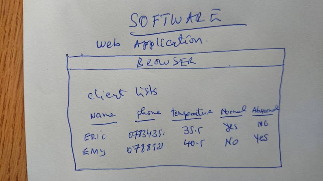
The followingpicture illustartes single users list page where users record are kept in web app. the system will save data and provide alerts whenever necessary.
PROJECT DEVELOPMENT
High level design of the Project
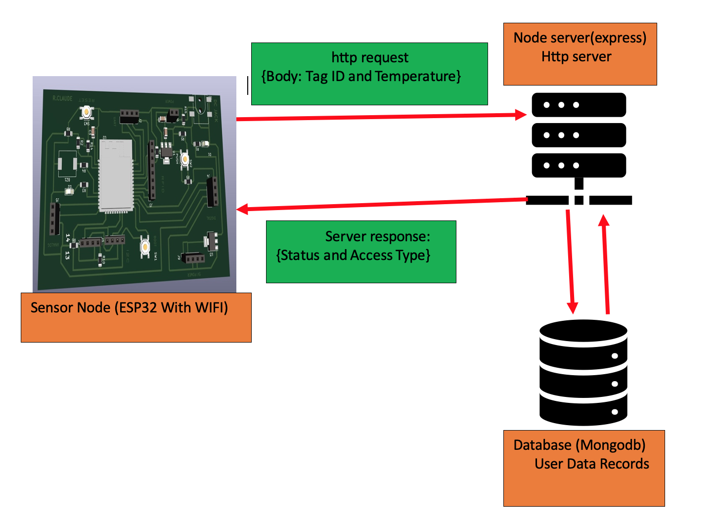
the project working principe is illustated in the following picture
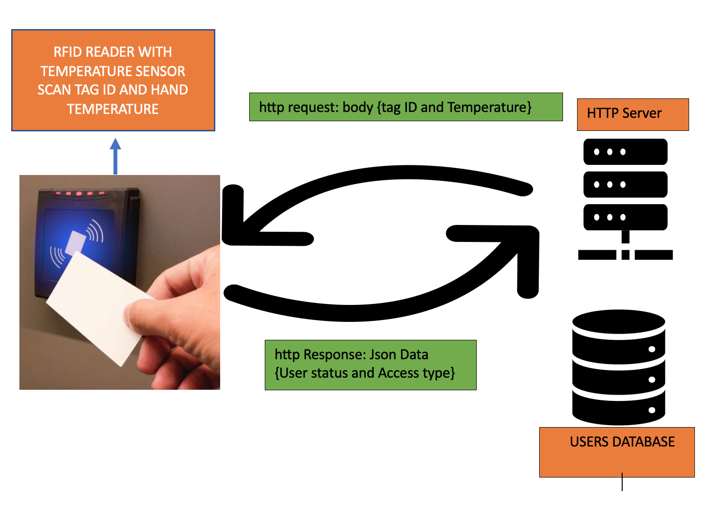
The above image illustate the high level archtecture of the system . The hardware device is the microcintroller which has an RFID Reader and infrared temperature sensor to sense user temperature before granting or denying acess to the given facility
The system has two parts: hardware device and server side . the hardware is the microcintroller which takes user temperatur . For this case i take hand temperature and tag ID and send to the remote server. the server receives the request and make queries against the database to verify the existance of the user in the database. if the user is registered and has a normal temperature, the server reply with Access is granted and record the data.
If the user is registered with Abnormal temperature The server reply with denied access and record the data
If the user is not registerd , his temperature is only shown on LCD screen and the access is automatically denied for the requested access
List of Materials needed for this project
| NO | ITEM | SPECIFICATION | QUANTITY | MATERIAL SHOPPING | IMAGE |
|---|---|---|---|---|---|
| 1 | ESP-WROM-32 | ESP-WROM-32 CHIP which as wifi and bluetooth | 1 | ESP-WROM-32 | 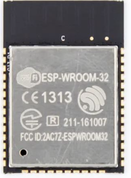 |
| 2 | MLX90614 | infrared temperature sensor | 1 | MLX90614 | 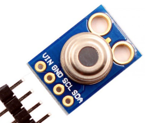 |
| 3 | OLED DISPLAY | 0.96 INCH OLED DISPLAY | 1 | OLED DISPLAY | 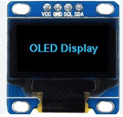 |
| 4 | Solenoid Electric Lock | 12V solenoid valve for opening and closing gate | 1 | solenoid electric lock | 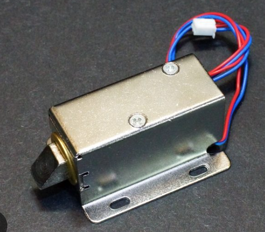 |
| 5 | Relay baord | 5V single channel relay baord | 1 | Relay baord | 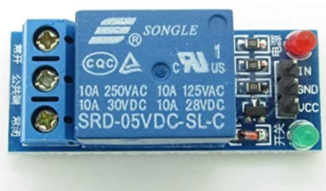 |
| 6 | RFID READER | MFRC522 RFID READER | 1 | Relay baord | 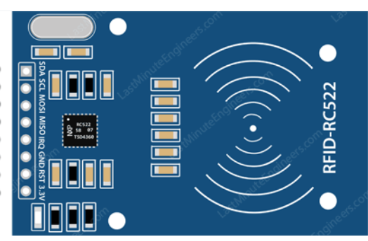 |
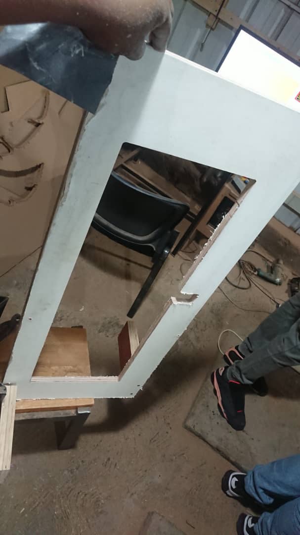
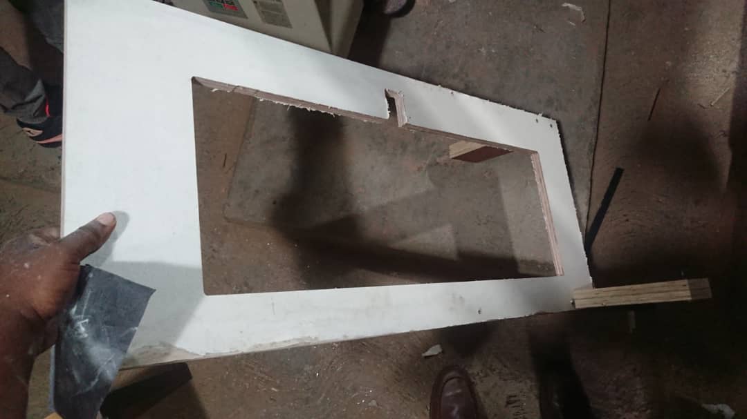
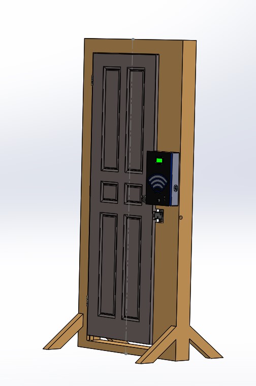
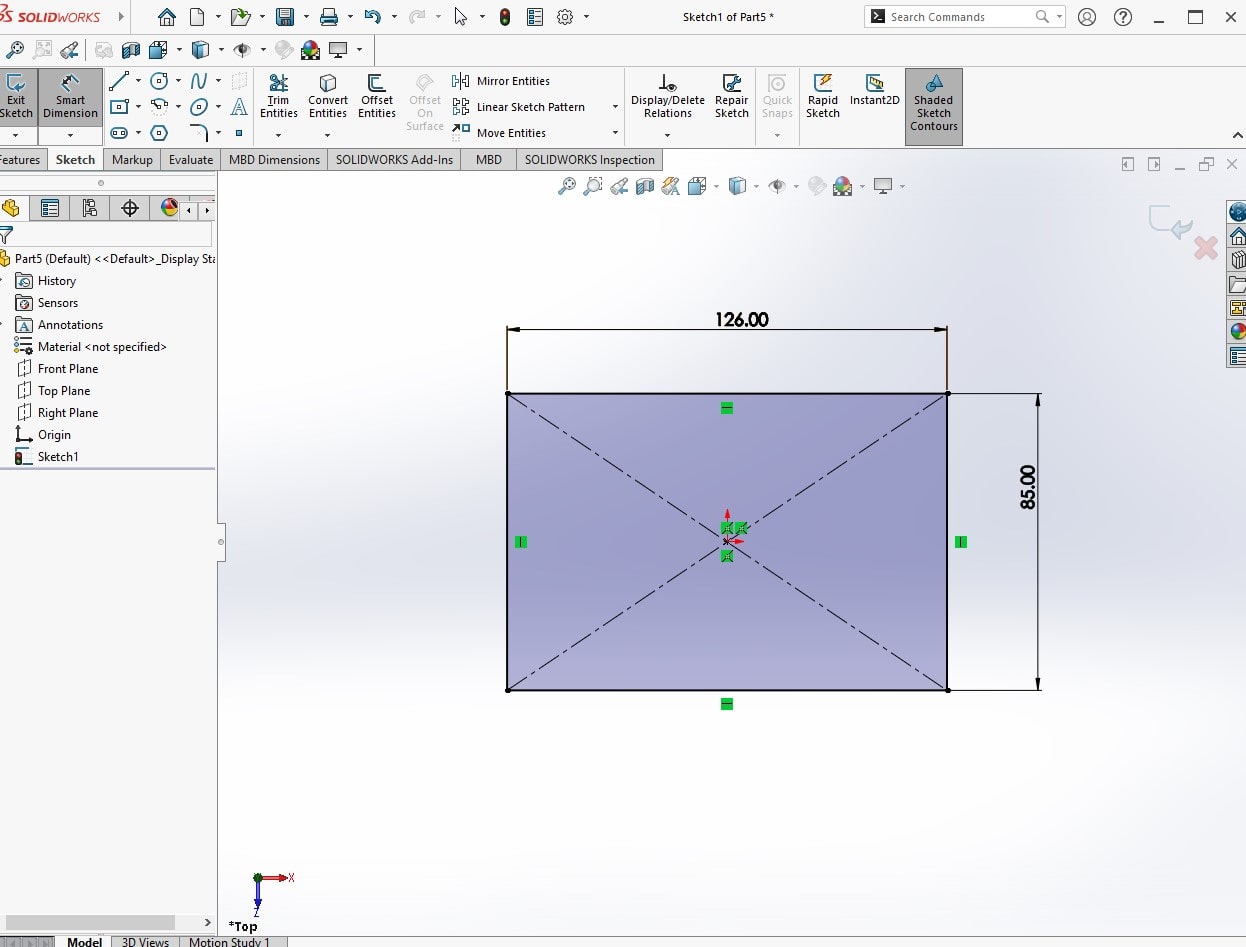
Mechanical Desing of the SYstem
My system is composed of circuit enclosure and door lock system in order to make mechanical structure of the main idea . i have used solid works for designing the door and the pcb circuit inclosure
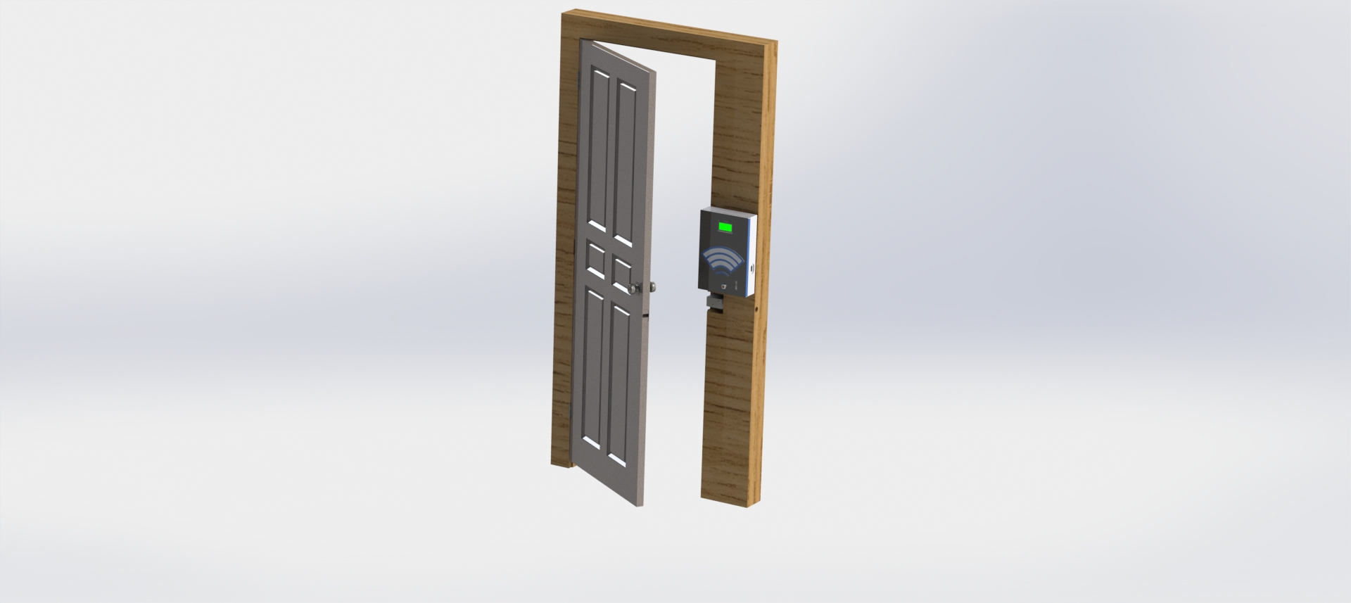
Video illustrating the mechanical system
ELECTRONIC CIRCUIT DESIGN AND PCB PRODUCTION
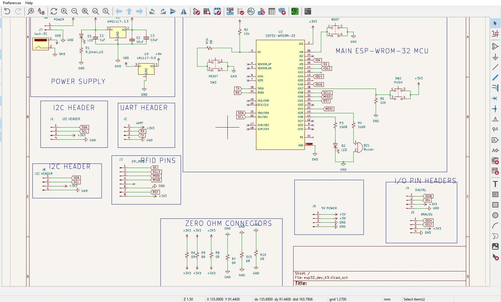
to produce the circuit , i have used kicadsoftware to desing my schematic and pcb. The software is open source and it is rich with many features available in commercial versions
To be sure abou the use of esp-wrom-32 I/O pins , i was referenced hereand the following images helped me to know the I/O to be used to match with the I/O available in arduino firmware cause i will be using arduino IDE in programming
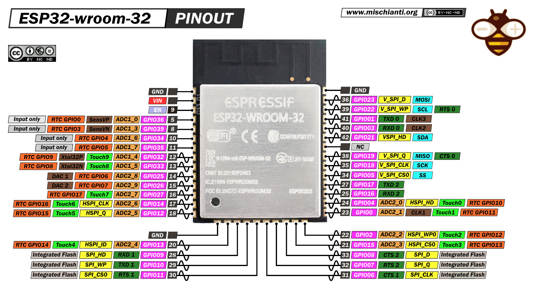
The design includes the ESP-WROM32, nad necessary terminals for I2C communication and mfrc522 rfid reader
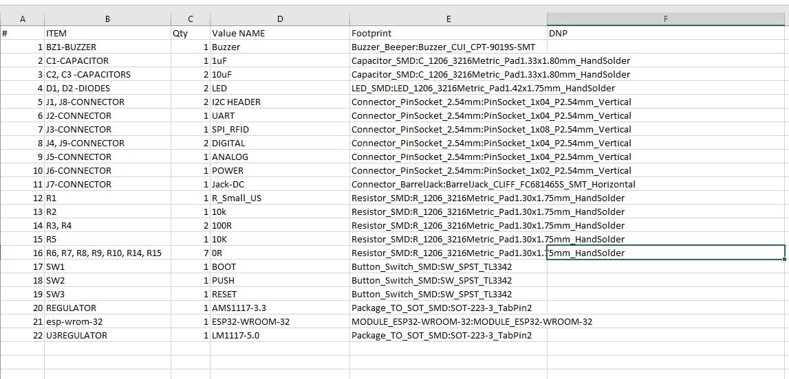
The following is the list of components used for my circuit. those items will be soldered on final pcb after milling
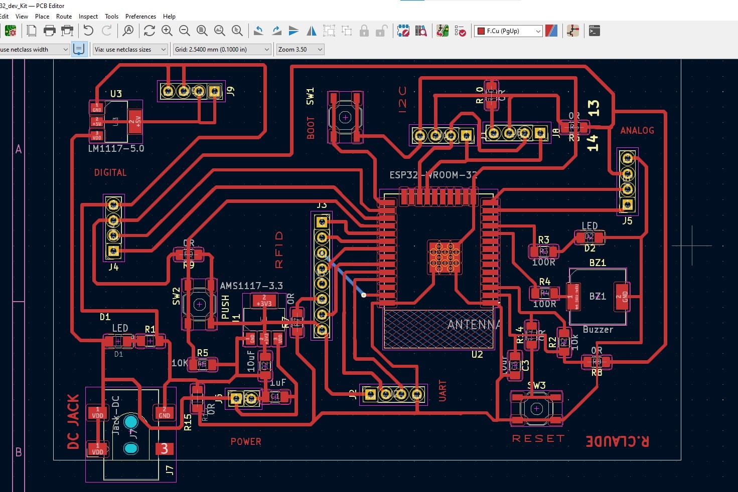
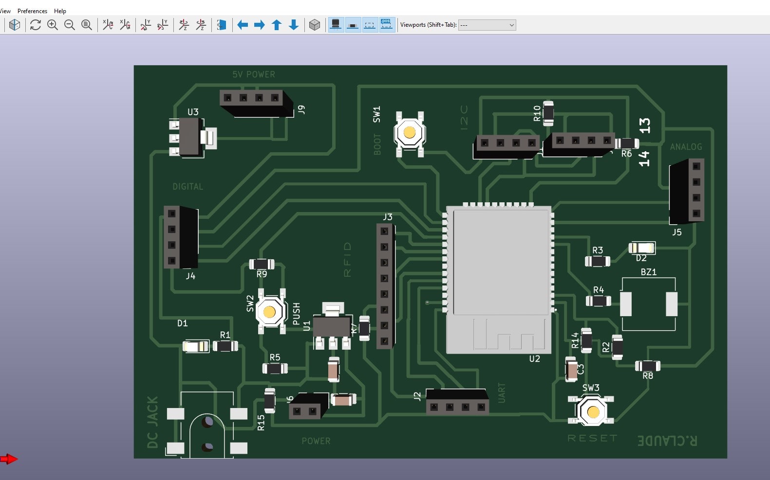
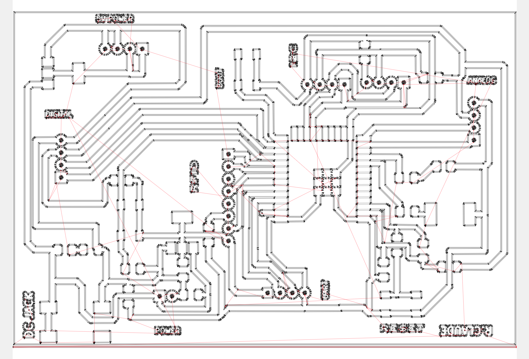
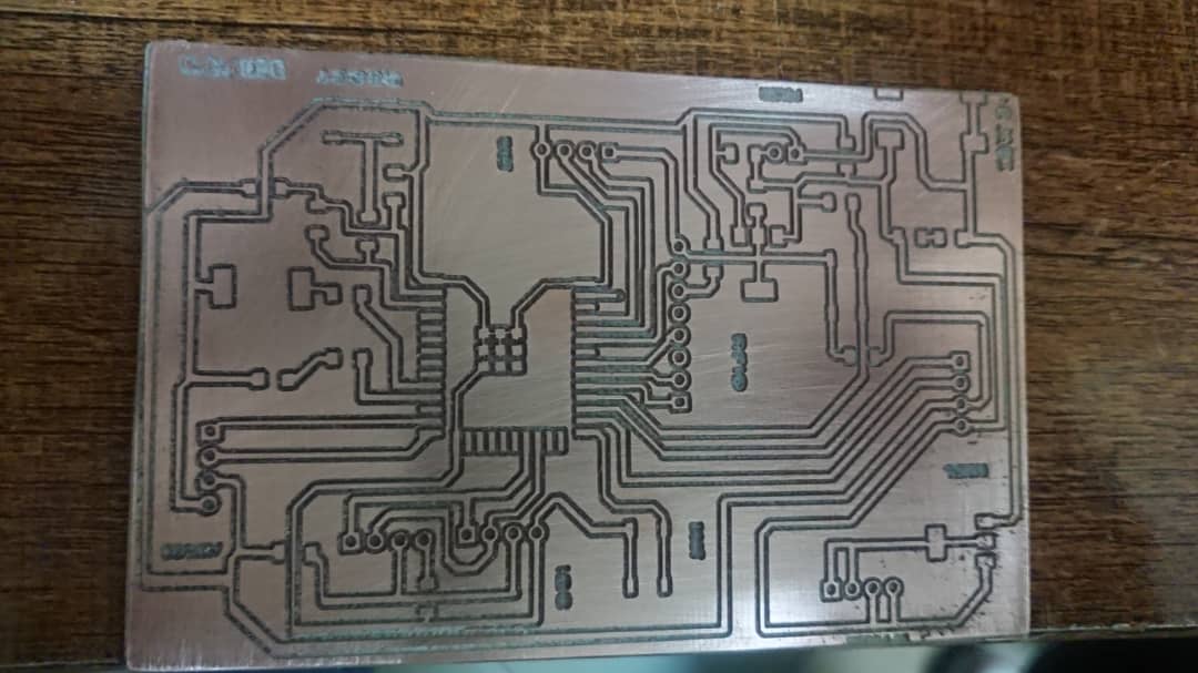
After making the schematic , the next step is to route the pcb in order to get the drill files for pcb production. the following is my routed pcb design
The next step is to see the 3D illustration of my PCB. KICAD has 3D Viewer which helped me to view pcb layout
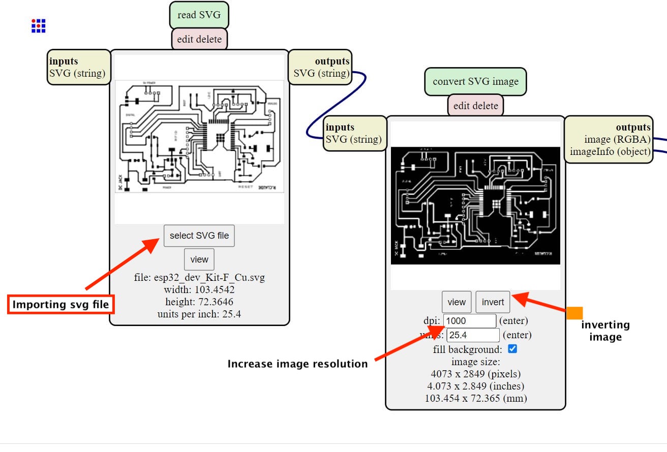
After making the pcb , the next process is to gerate the image that shows drill lines to be used to generate g-code for the milling machine. here i generated the SVG image which is the extension that kicad generates

then we have to generate edge cut file in svg to be used to generate g-code for edge cutting of our pcb

The next step is to generate g-code for our srm-20 milling machines . to do that i have used a called mods to geneate toolpath
To do that we just import the saved svg image from kicad in mods and then set the needed parameters to generate the toolpath
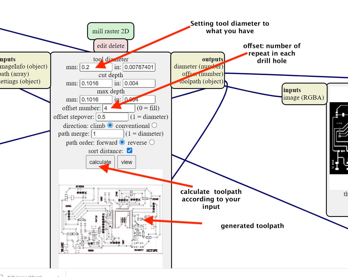
Generated toolpath
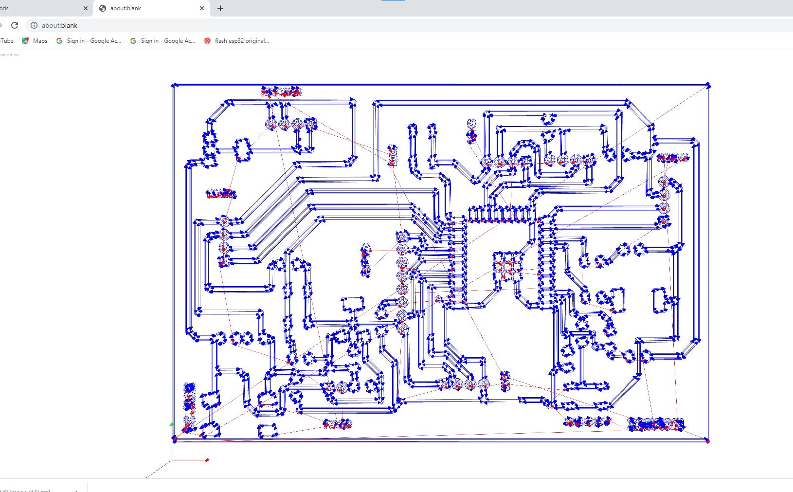
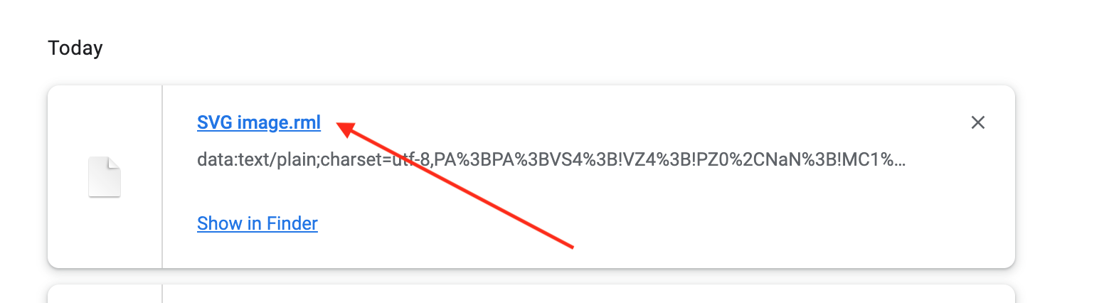
in modes you have to add a functionality to save g-code in system file of your machine from the browser
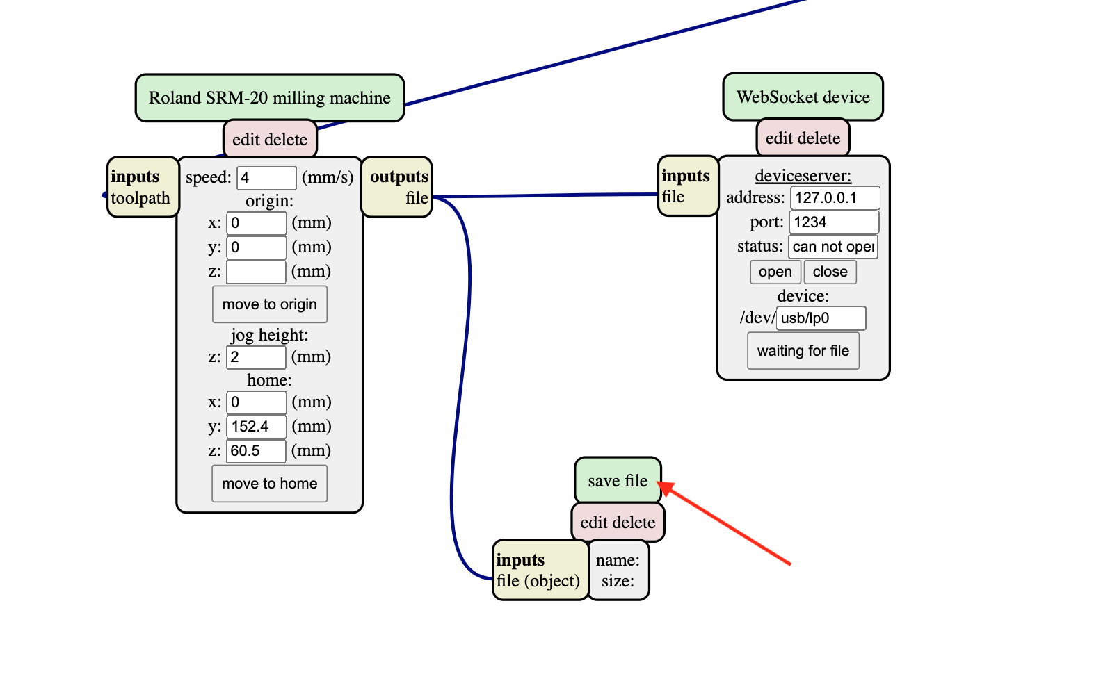
the Generated file has .rml as file extension and it contains g-code for the roland srm-20 milling machine
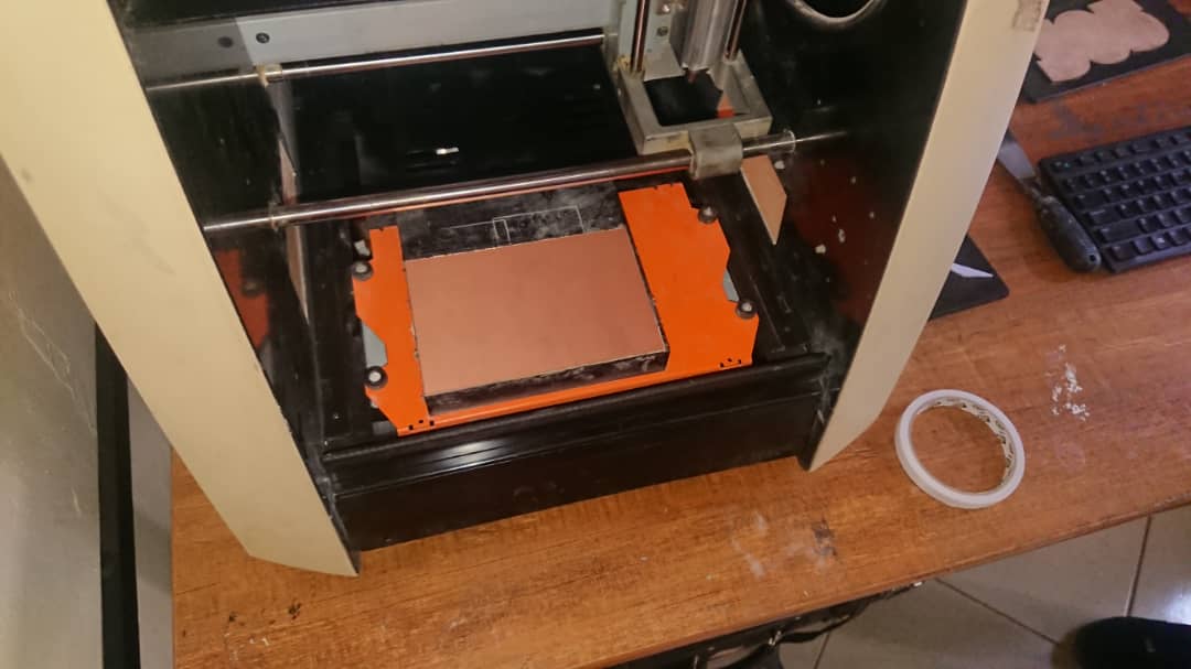
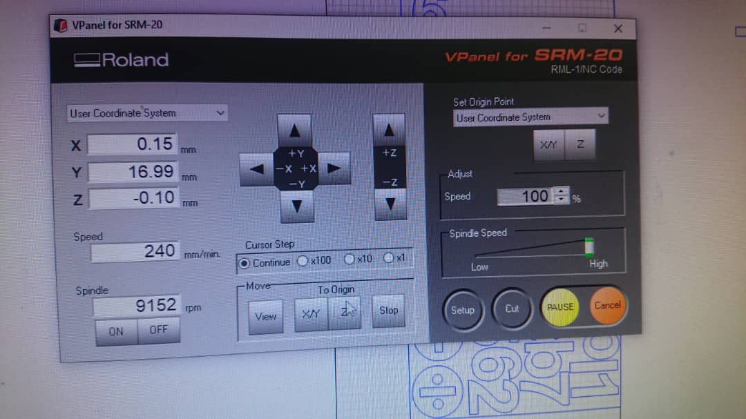
Producing the PCB
The generated file is used within roland srm-2o milling machine with single sided pcb .
To use the SRM-20 for PCB fabrication, the following steps are typically followed:
- Design the PCB layout using a software program such as Eagle, KiCAD, or Altium.
- Export the design file as a Gerber file, which contains the necessary information for the milling machine to create the PCB.
- Open the Roland SRM-20 milling machine and turn it on.
- Insert the material to be milled into the machine and secure it in place.
- Load the Gerber file into the milling software that comes with the machine.
- Set the milling parameters, such as milling depth and speed.
- Start the milling process.
- Once the milling is complete, remove the PCB from the machine and inspect it for any defects.
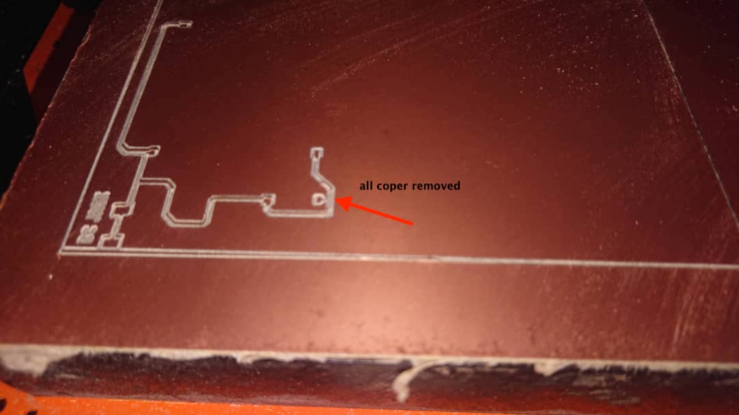
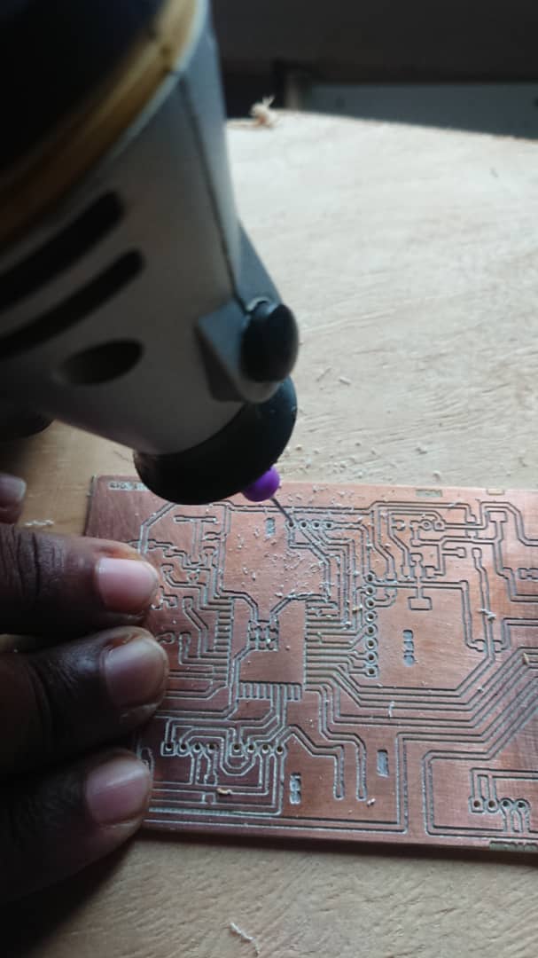
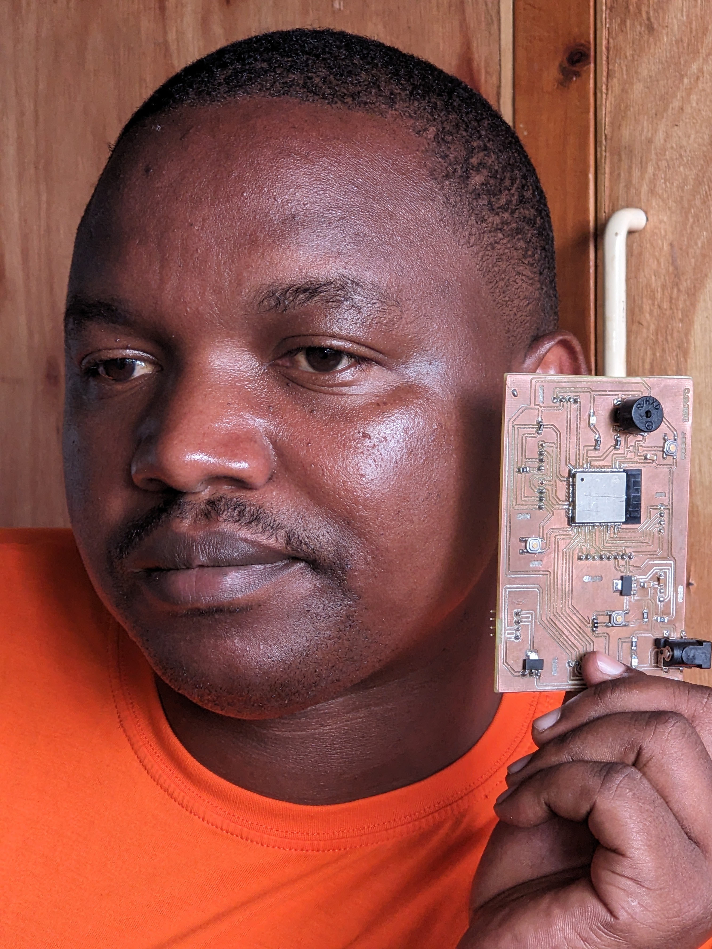
results of pcb mill process
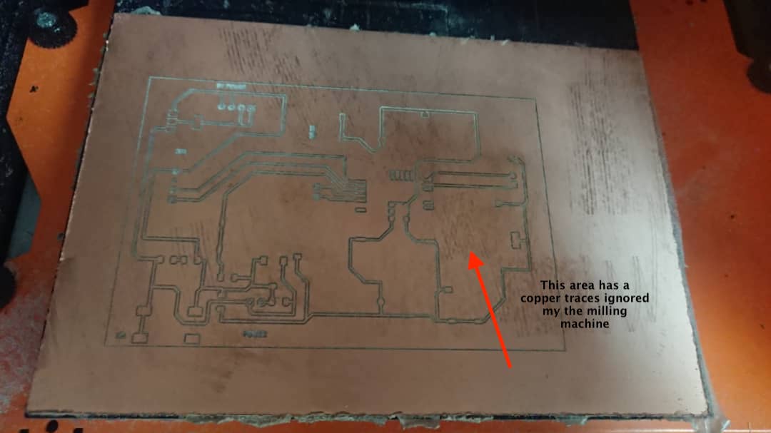
After fixing the above issues mentioned , then this is my final pcb
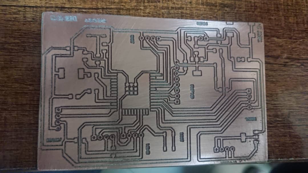
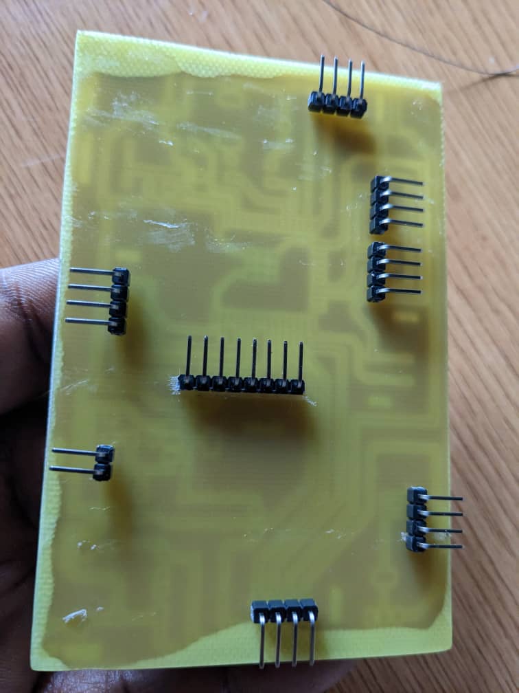
This was was i wanted and it looks nice and i can do my rest of work on it . the next steps in to drill holes for my pin headers and i used a drilling machine for that
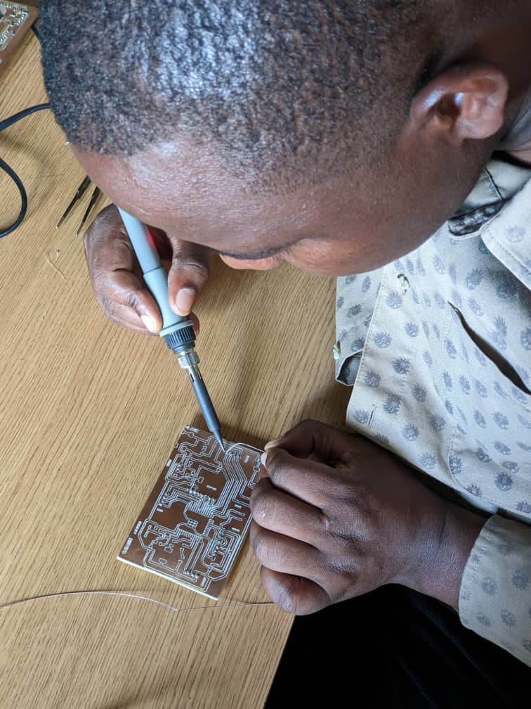
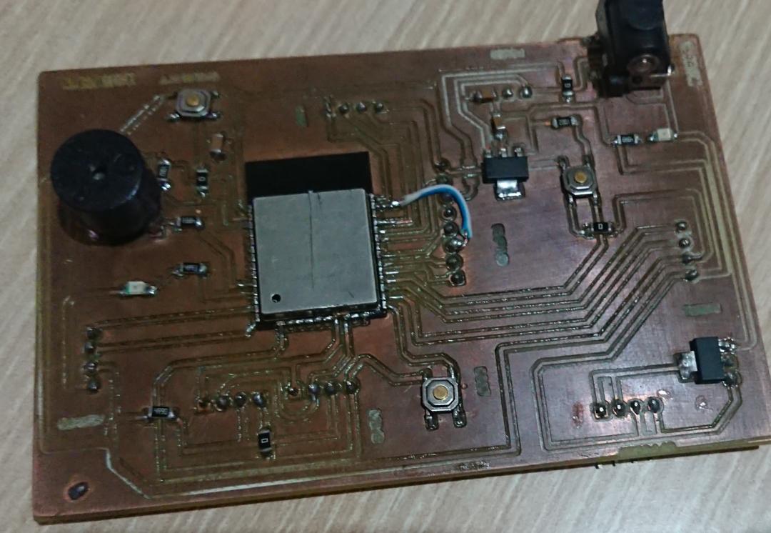
After having a complete pcb , i started soldering components with soldering iron
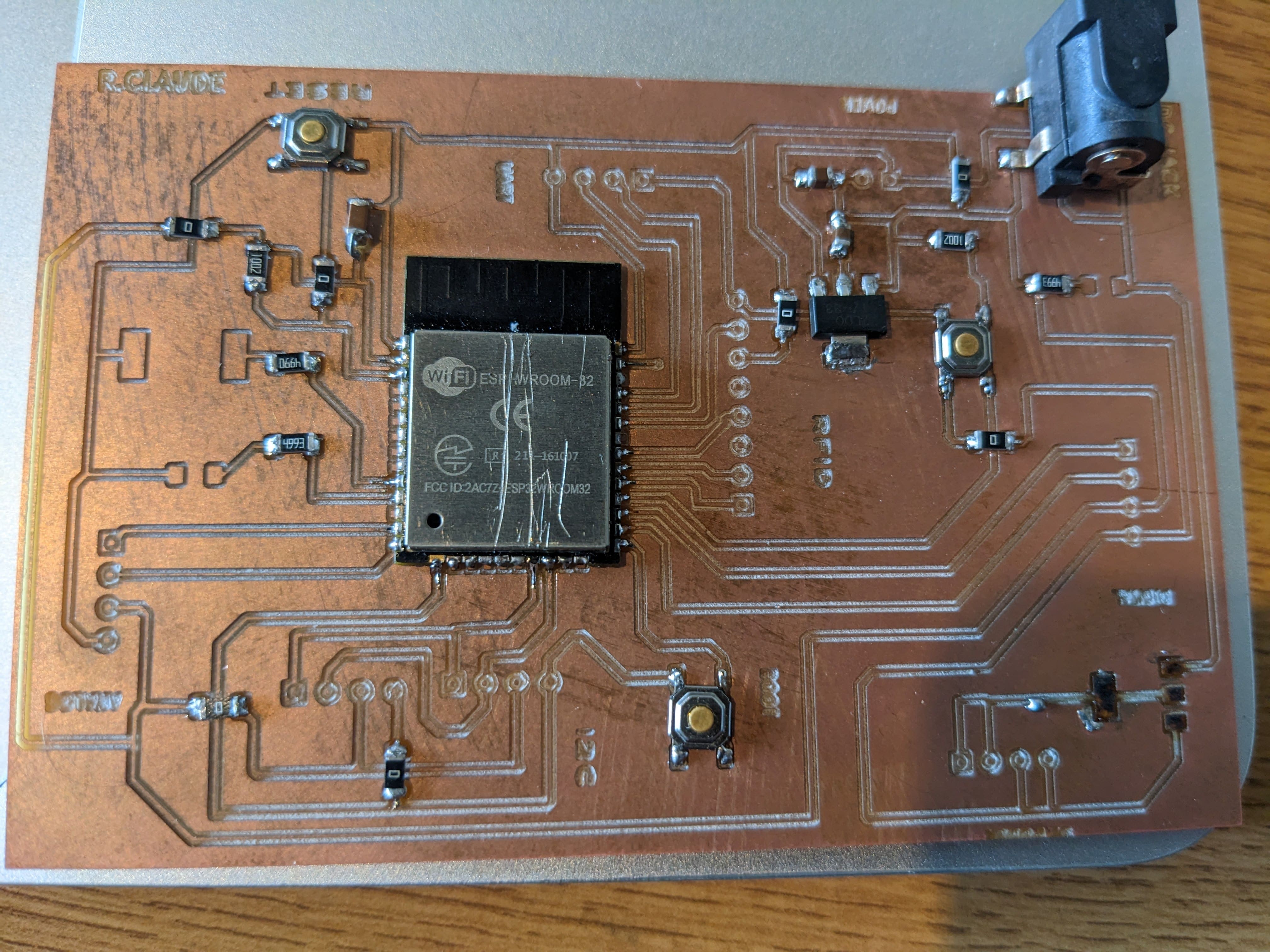
Final soldered pcb
Interfacing with Sensors and Actuators
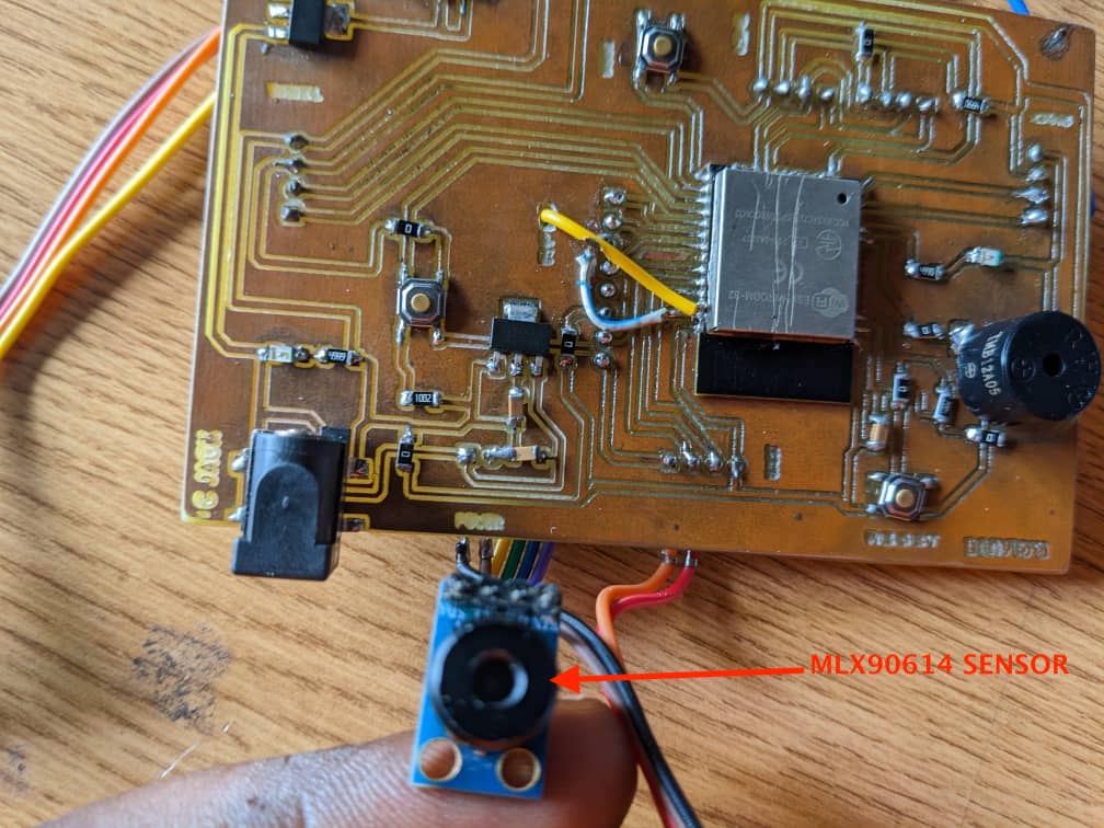
After Making PCB and soldering all components , i proceed with interfacing sensors which are MFRC522 rfid reader and MLX90614 INFRARED Temperature sensor.
TESTING MLX90614 S
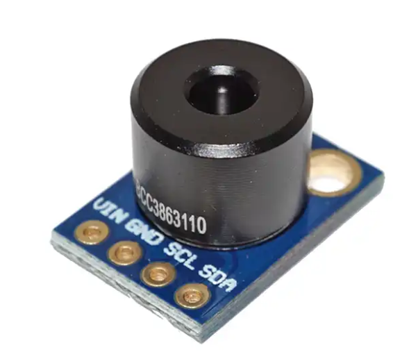
The following is the specifications of the sensor
| Specification | Value |
|---|---|
| Measurement Range | -40°C to +125°C |
| Ambient Temperature Range | -40°C to +85°C |
| Accuracy | ±0.5°C (within 0°C to +50°C) |
| Resolution | 0.02°C |
| Field of View (FOV) | 90° |
| Supply Voltage | 2.6V to 3.6V |
| Interface | I2C |
| Package Type | To-39 |
the sensor testing have been documented in the week of input where it was interfaced to ESP-WROM-32 MCU via I2C and it was able to read body temperatue successfully
OUTPUT
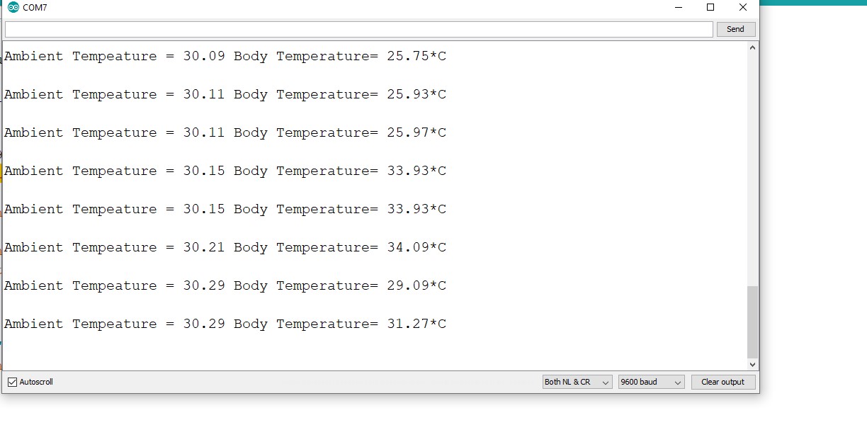
the sensor produced the desired output and it was tested on different objects temperature and it reacts to given objects temperature in its range of measurements. the next step is to test the RFID READER
Used code
          #include < Wire.h >
            #include < Adafruit_MLX90614.h >

            Adafruit_MLX90614 mlx = Adafruit_MLX90614();
            void setup() {
              Serial.begin(9600);
              Wire.begin();

              mlx.begin(); // Initialize the MLX90614 sensor
            }
            void loop() {
              float ambientTemp = mlx.readAmbientTempC(); // Read ambient temperature in degrees Celsius
              float objectTemp = mlx.readObjectTempC(); // Read object temperature in degrees Celsius
              Serial.print("Ambient Temperature: ");
              Serial.print(ambientTemp);
              Serial.print(" °C");
              Serial.print("Object Temperature: ");
              Serial.print(objectTemp);
              Serial.print(" °C");
              Serial.println();
              delay(1000); // Delay for 1 second
            }
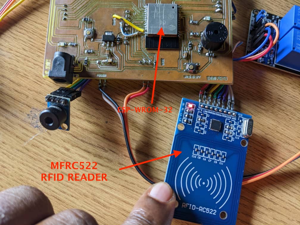
TESTING MFRC522 READER

the following is the specifications of mfrc522 rfid reader
| Specification | Value |
|---|---|
| Operating Frequency | 13.56 MHz |
| Protocol Support | ISO/IEC 14443A |
| Card Read Distance | Up to 30 mm (depending on card/tag) |
| Operating Voltage | 3.3V |
| Operating Current | 13-26mA |
| Interface | SPI |
| Max Data Transfer Rate | 10 Mbps |
| Supported Cards/Tags | MIFARE Classic 1K, MIFARE Classic 4K, MIFARE Ultralight, MIFARE DESFire, NTAG203, and more |
| Operating Temperature | -20°C to +80°C |
| Dimensions | 40mm x 60mm |
USED CODE
    #include < SPI.h >
      #include < MFRC522.h >

      #define RST_PIN 14    // RST pin connected to GPIO 14
      #define SDA_PIN 5     // SDA pin connected to GPIO 5
      MFRC522 mfrc522(SDA_PIN, RST_PIN);  // Create MFRC522 instance
      void setup() {
        Serial.begin(9600);
        SPI.begin();       // Initialize SPI bus
        mfrc522.PCD_Init(); // Initialize MFRC522 RFID reader

        Serial.println("Ready to read RFID cards!");
      }
      void loop() {
        // Check if a new card is present
        if (mfrc522.PICC_IsNewCardPresent() && mfrc522.PICC_ReadCardSerial()) {
          // Read card UID
          Serial.print("Card UID: ");
          for (byte i = 0; i < mfrc522.uid.size; i++) {
            Serial.print(mfrc522.uid.uidByte[i] < 0x10 ? " 0" : " ");
            Serial.print(mfrc522.uid.uidByte[i], HEX);
          }
          Serial.println();
          // Halt PICC
          mfrc522.PICC_HaltA();
          // Stop encryption on PCD
          mfrc522.PCD_StopCrypto1();
        }
      }
Here , the rfid reader was able to read the rfid tag having 13.56 mhz
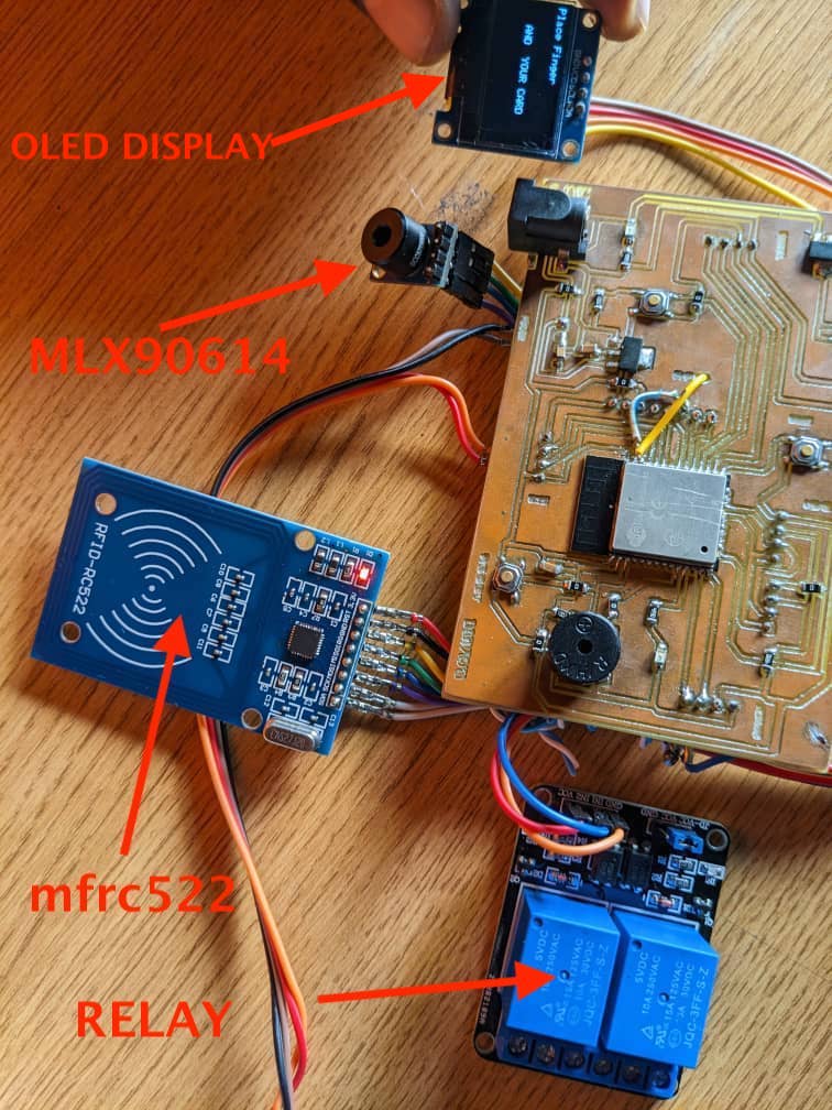
TESTING BOTH MLX90614, RFID AND OLED DISPLAY
here i tested MLX90614, rfid and oled display to see how they work togather
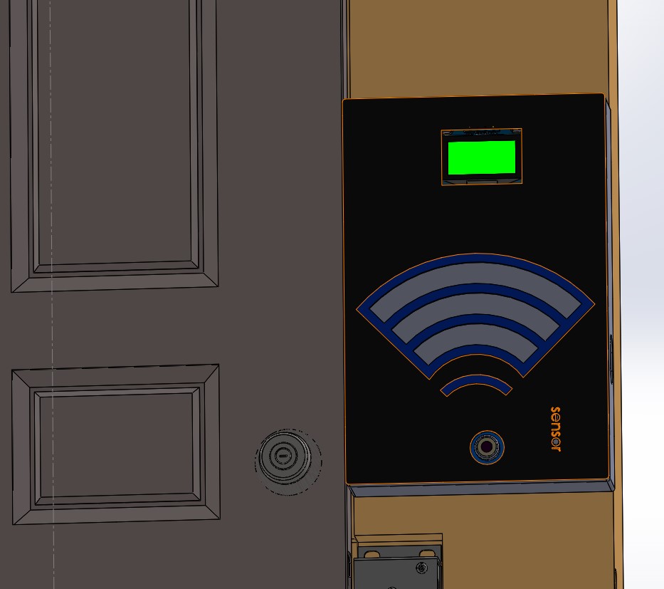
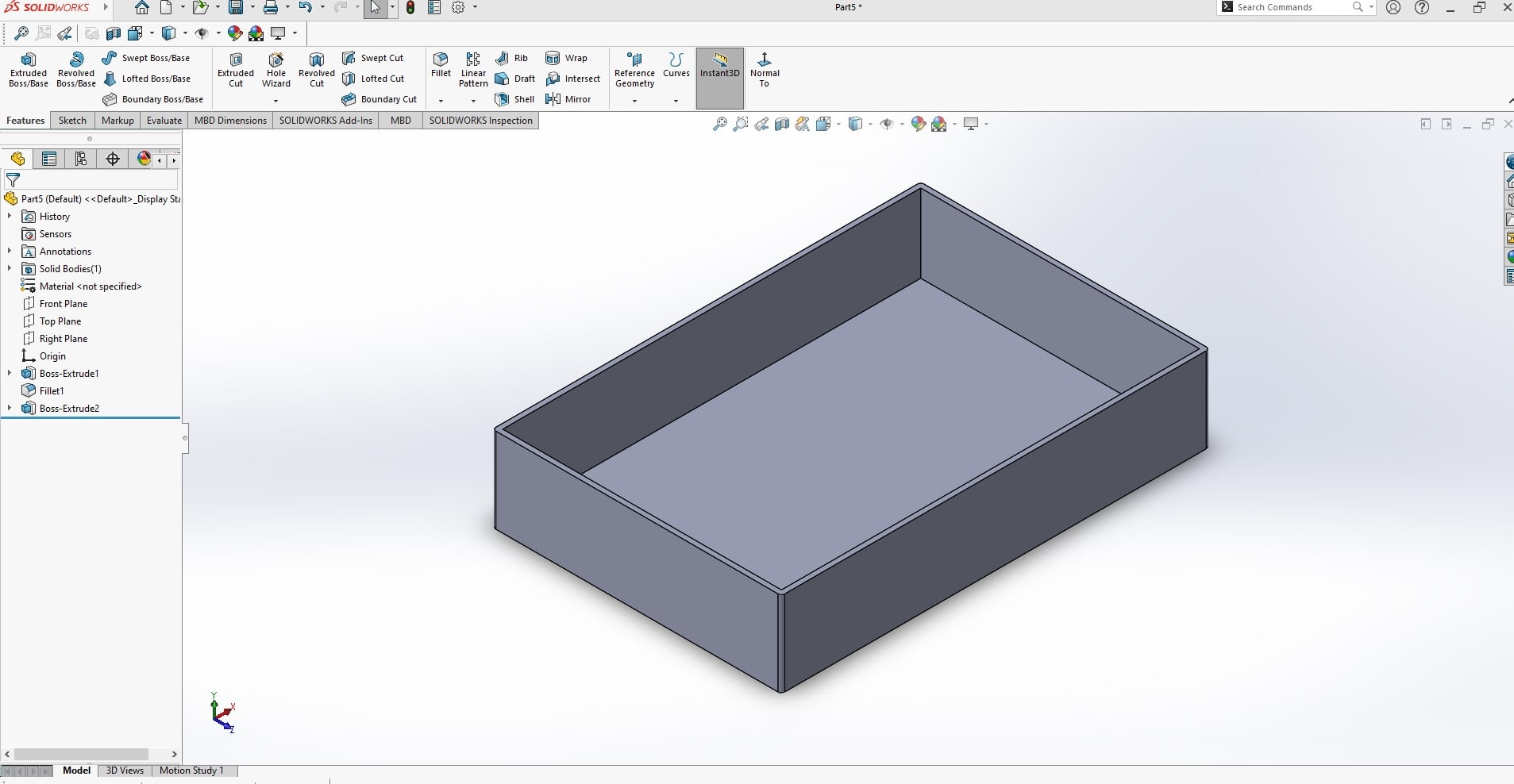
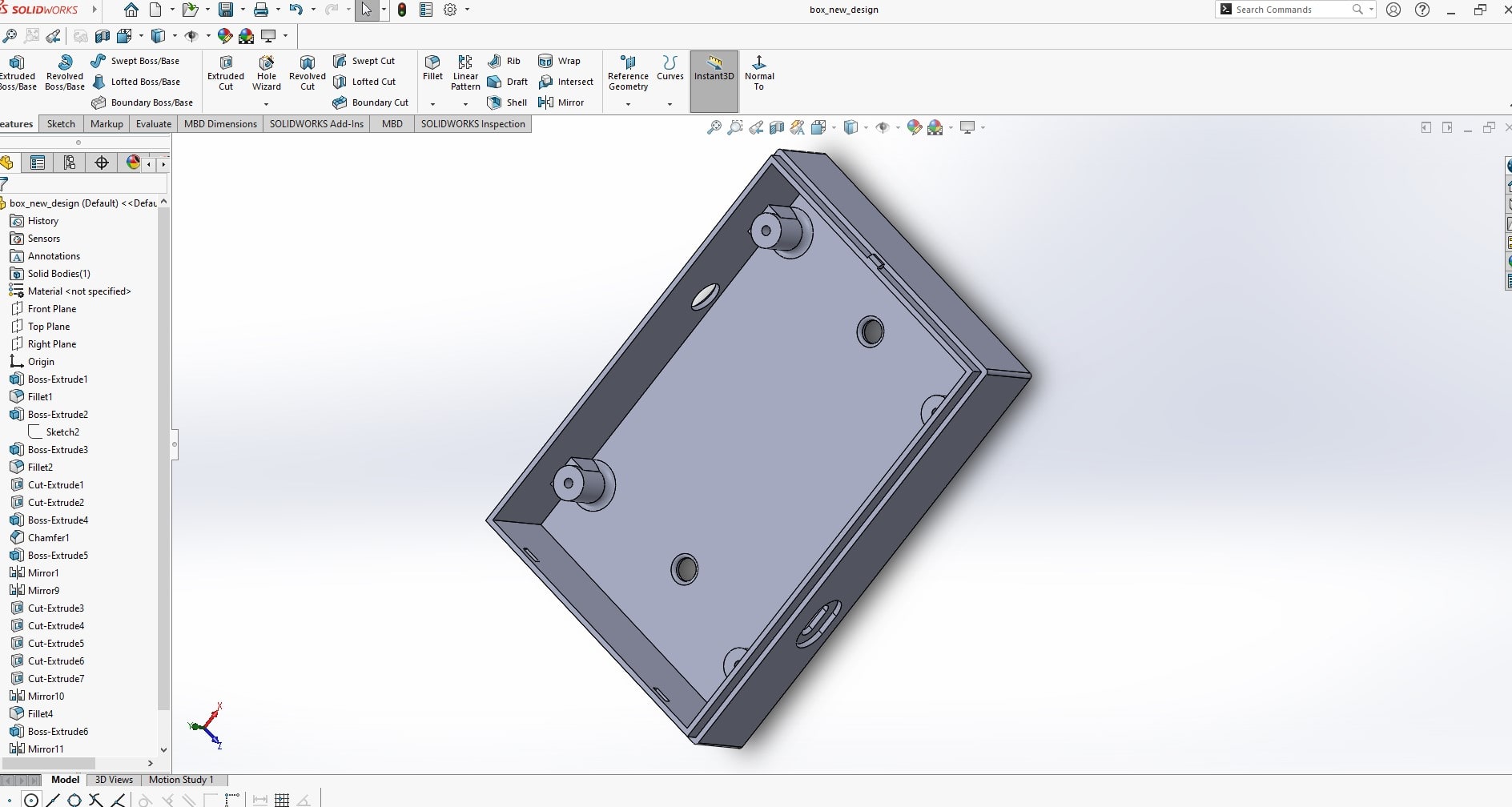
Final Project Cover Box Modeling and Printing
The final project prototype circuit should be placed inside the box enclosure
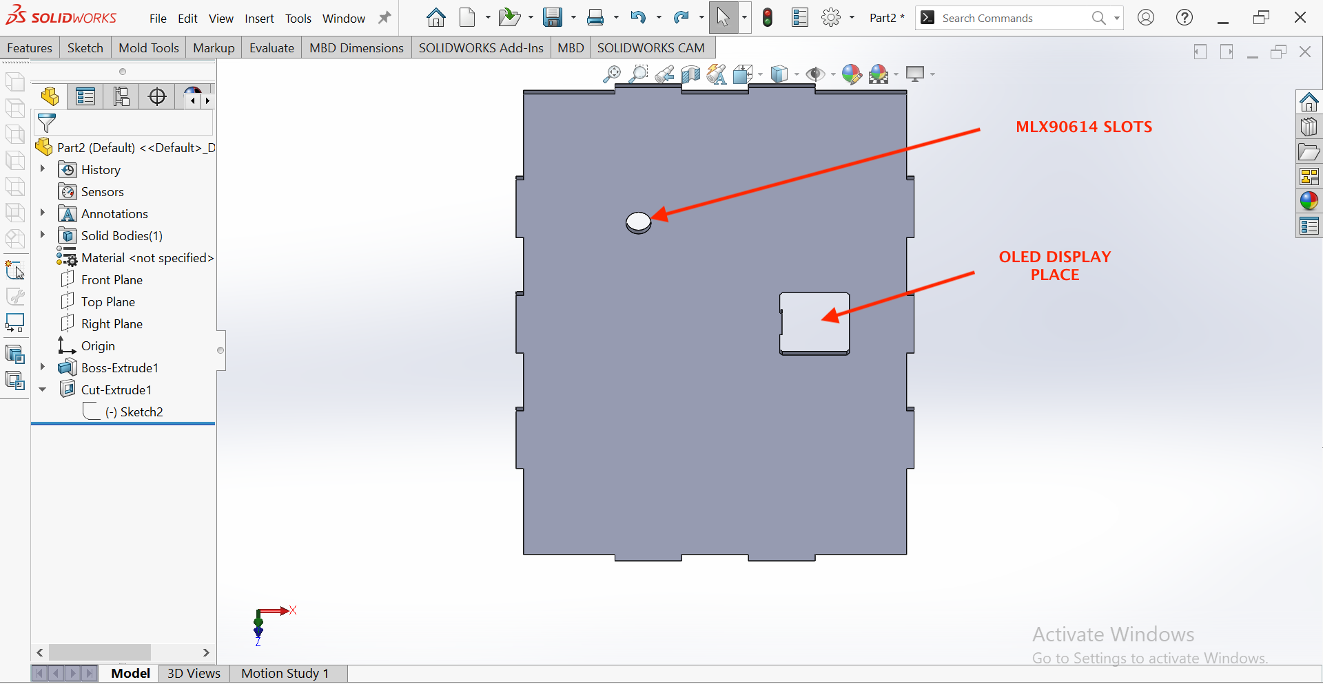
The purpose of creating an electronic circuit cover box in SolidWorks is to provide physical protection for the electronic components and circuits inside. The cover box serves as a barrier against environmental factors such as dust, moisture, and impacts that can damage the electronics. Additionally, the cover box can also play a role in reducing electromagnetic interference (EMI) and electromagnetic compatibility (EMC) issues, as it can act as a Faraday cage that shields the electronics from external electromagnetic fields.
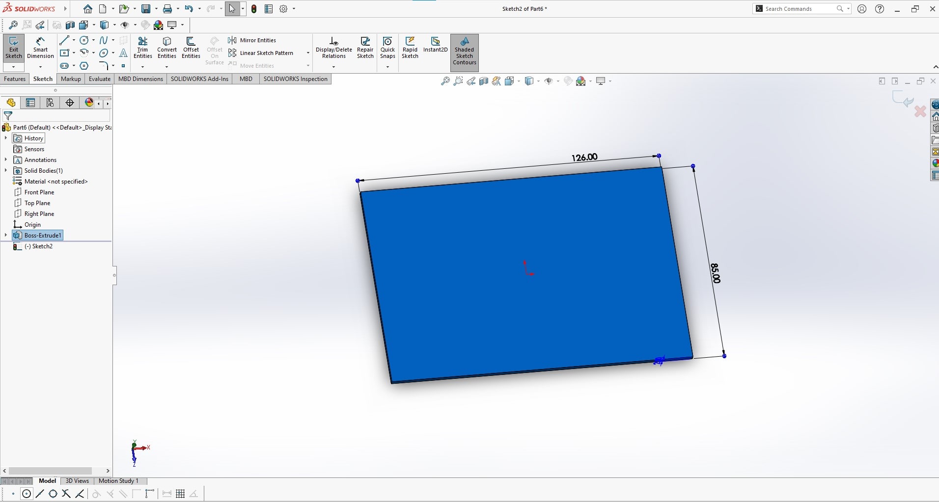
In SolidWorks, the cover box can be designed with precise dimensions and features such as ventilation holes, snap fits, and screw holes to accommodate the specific requirements of the electronic circuit. This allows for a custom-fit cover box that provides the necessary protection while allowing for easy access to the electronics when needed.
Because of the popularity of solidworks, i prefered to use it in order to be familiar with it and it will be beneficial in my daily task in fablab
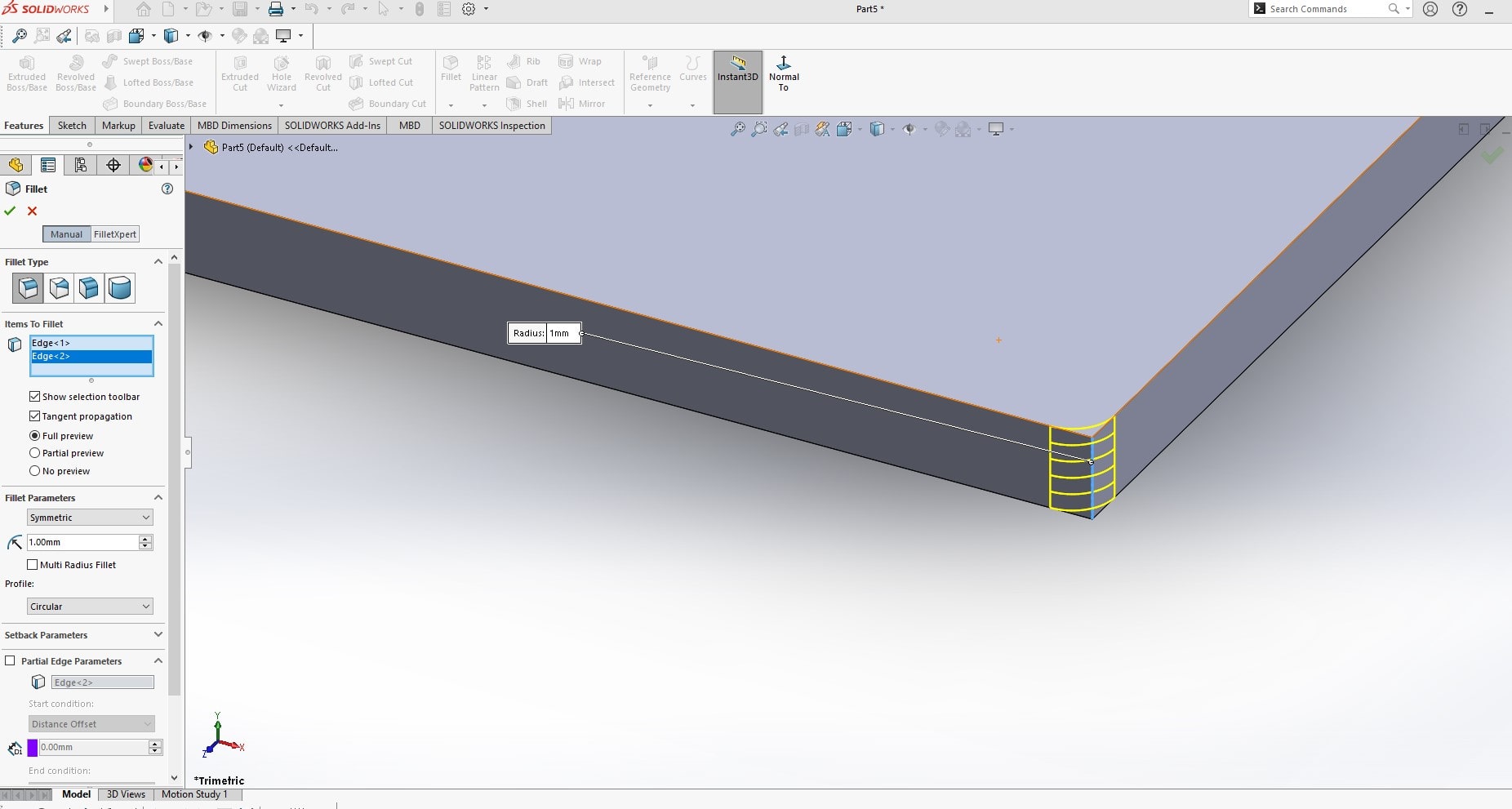
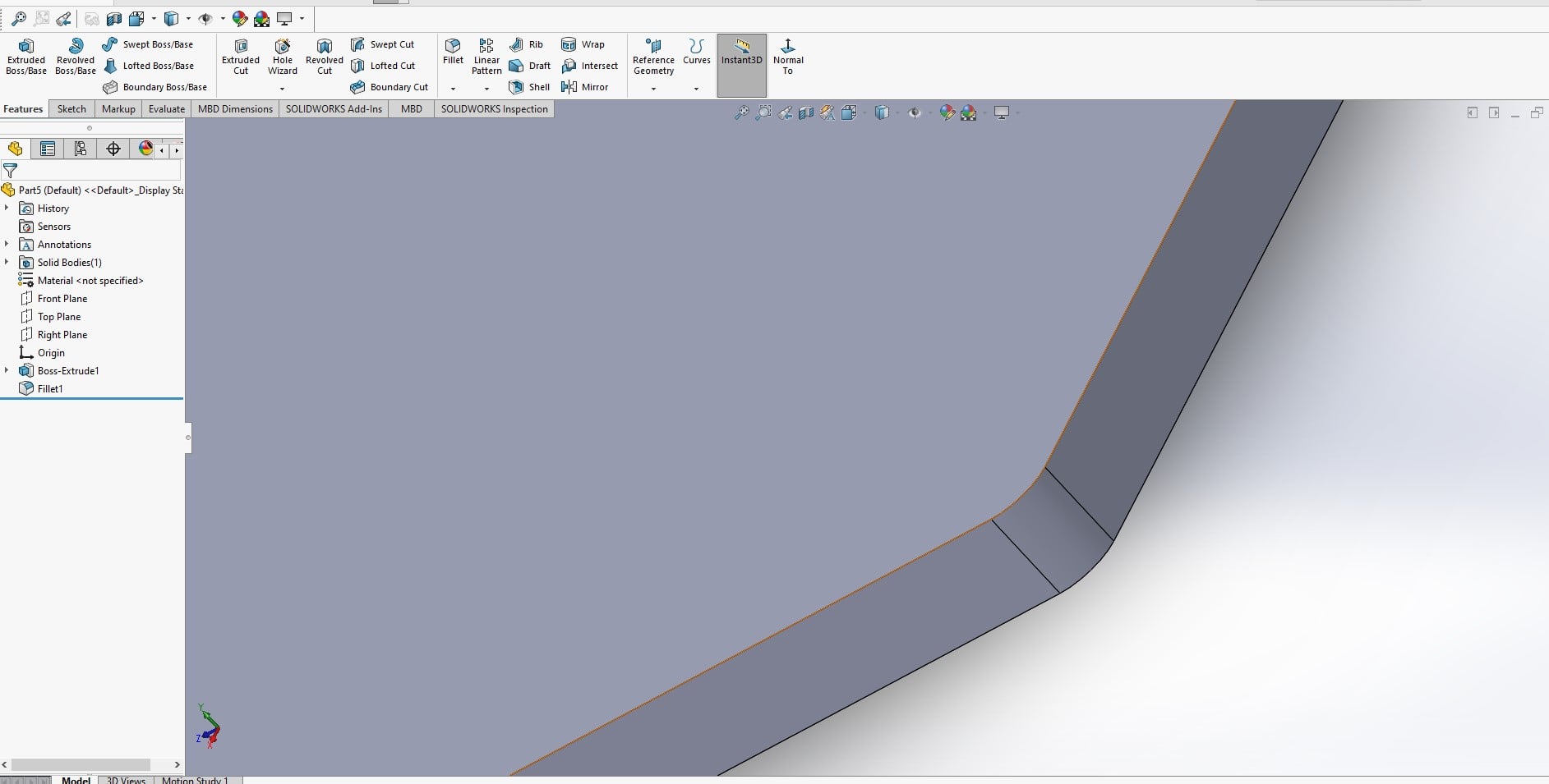
The fillet tool in SolidWorks is used to create rounded edges on parts and models. The fillet tool allows you to add a smooth radius transition between two intersecting surfaces, making the part more aesthetically pleasing and improving its overall design. The fillet tool can be applied to both 2D and 3D models, and it can be used to create fillets of various sizes and shapes. The fillet tool can also improve the functional performance of a part by reducing stress concentrations at sharp corners and i ncreasing its overall strength and durability. By rounding the edges of a part, the fillet tool can also improve its manufacturability, as it eliminates the need for sharp corner transitions that can be difficult to produce with certain manufacturing processes.

for 3D printing, i used ultimaker under-3 pro and creality slicer to print my design . i saved my sliced part to sd card then i inserted.
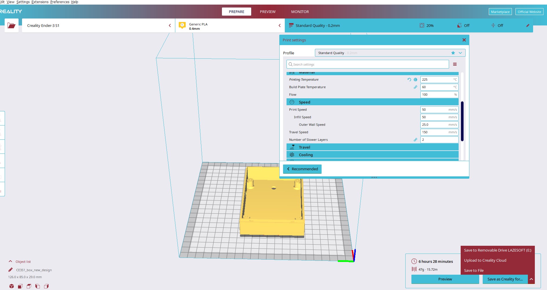
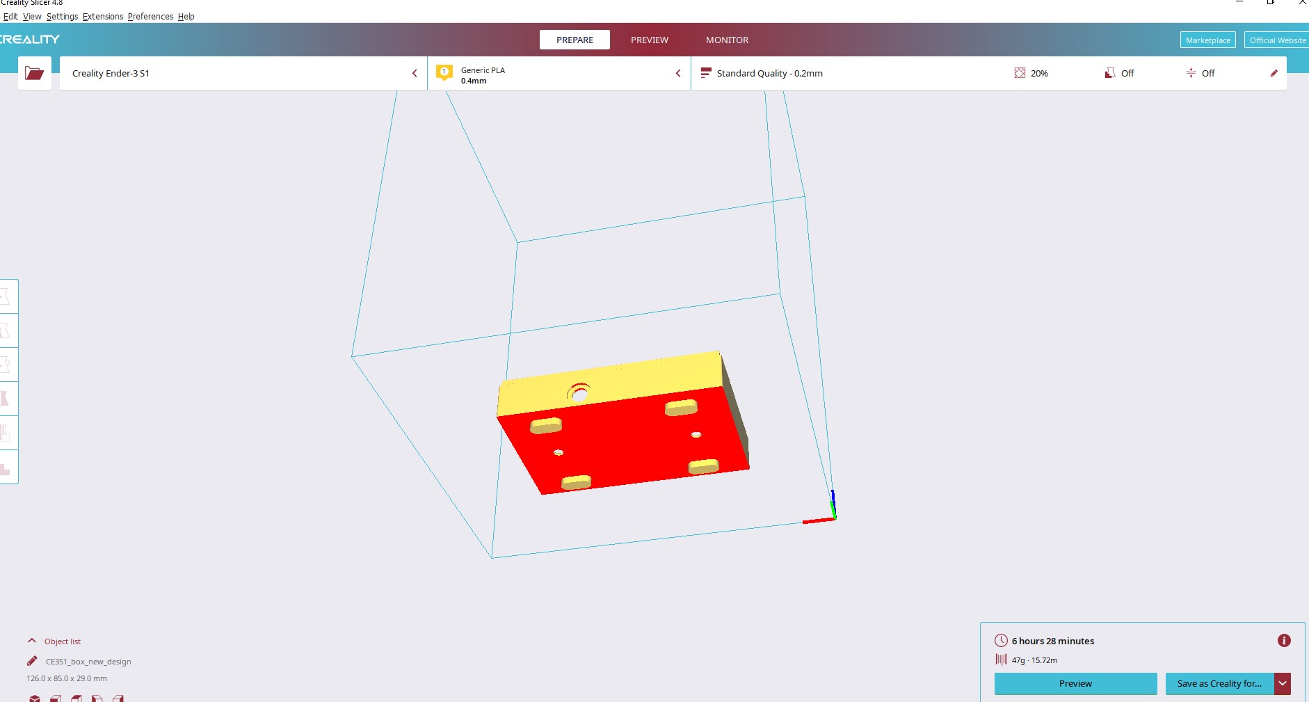
3D printing process in the Video
After all , i changed my mind about using 3D printed box cover. the error i made is to make an assumption that pcb will fit in the box. the stupidity i did is that i desinged the box before pcb ): thats is the reason i learnt. i have to start production after all design are completed
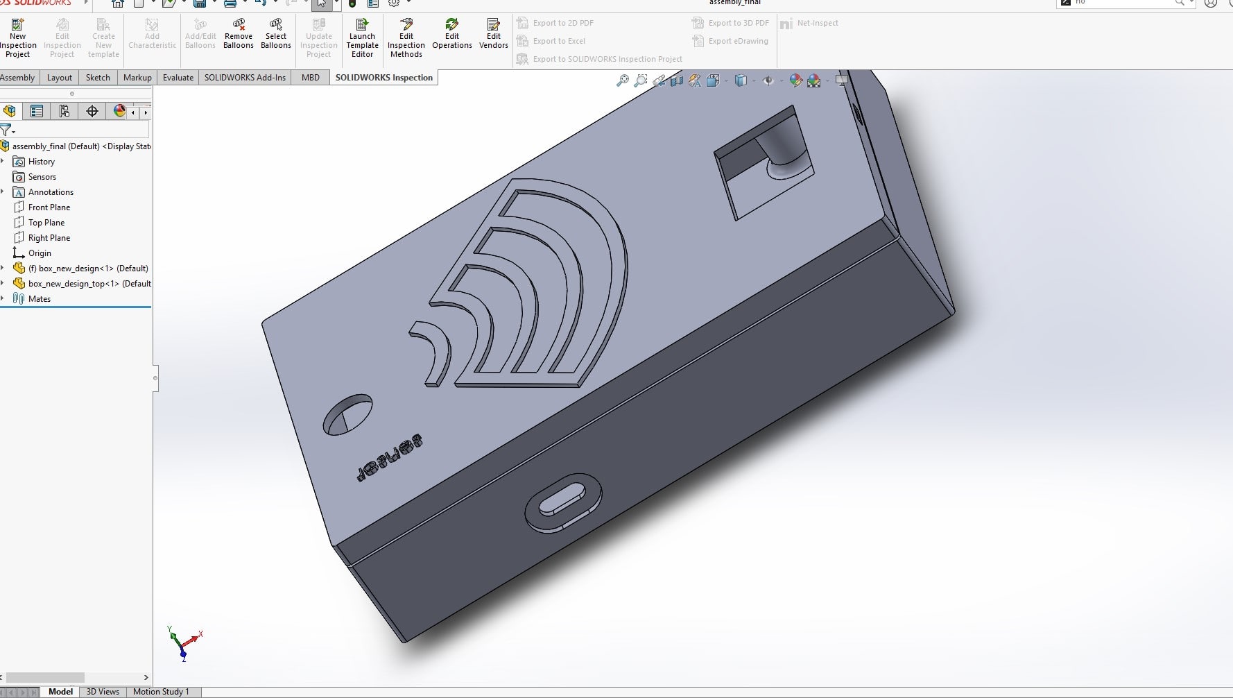
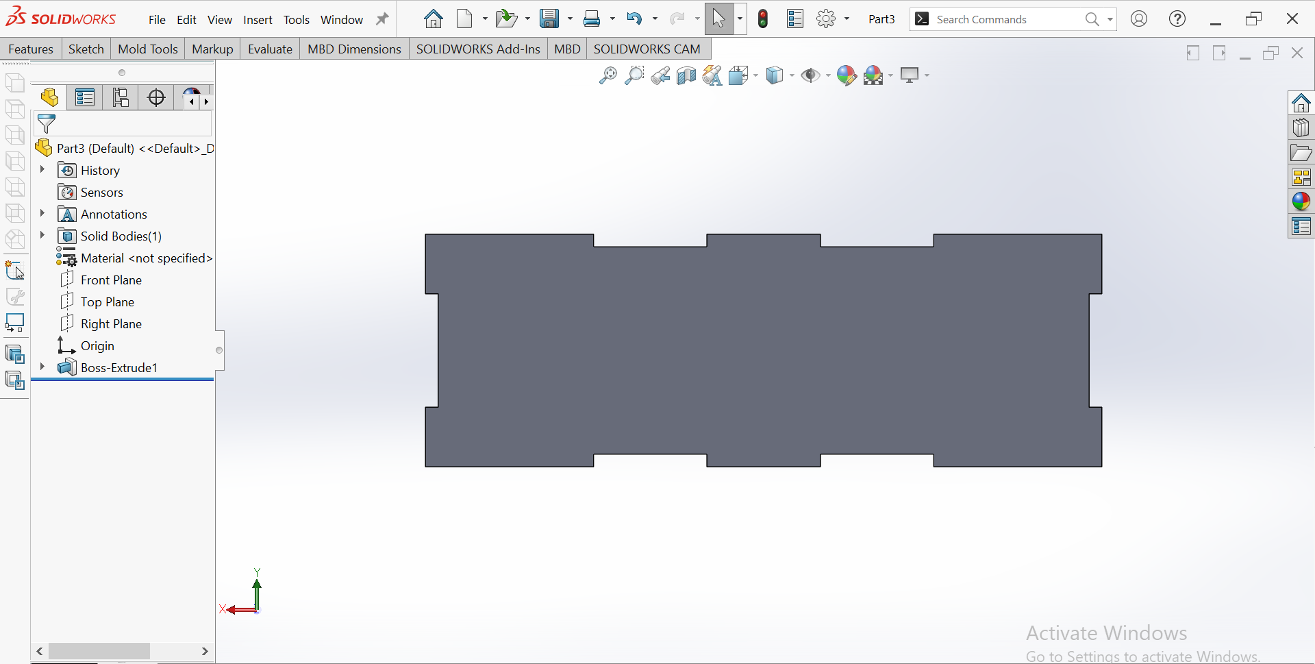
Sesign new cover box to be produced on MDF 3mm Sheet
no other choice i had after noticing that pcb is not fitting, rather tahn new design and production process
the design is done in solidworks
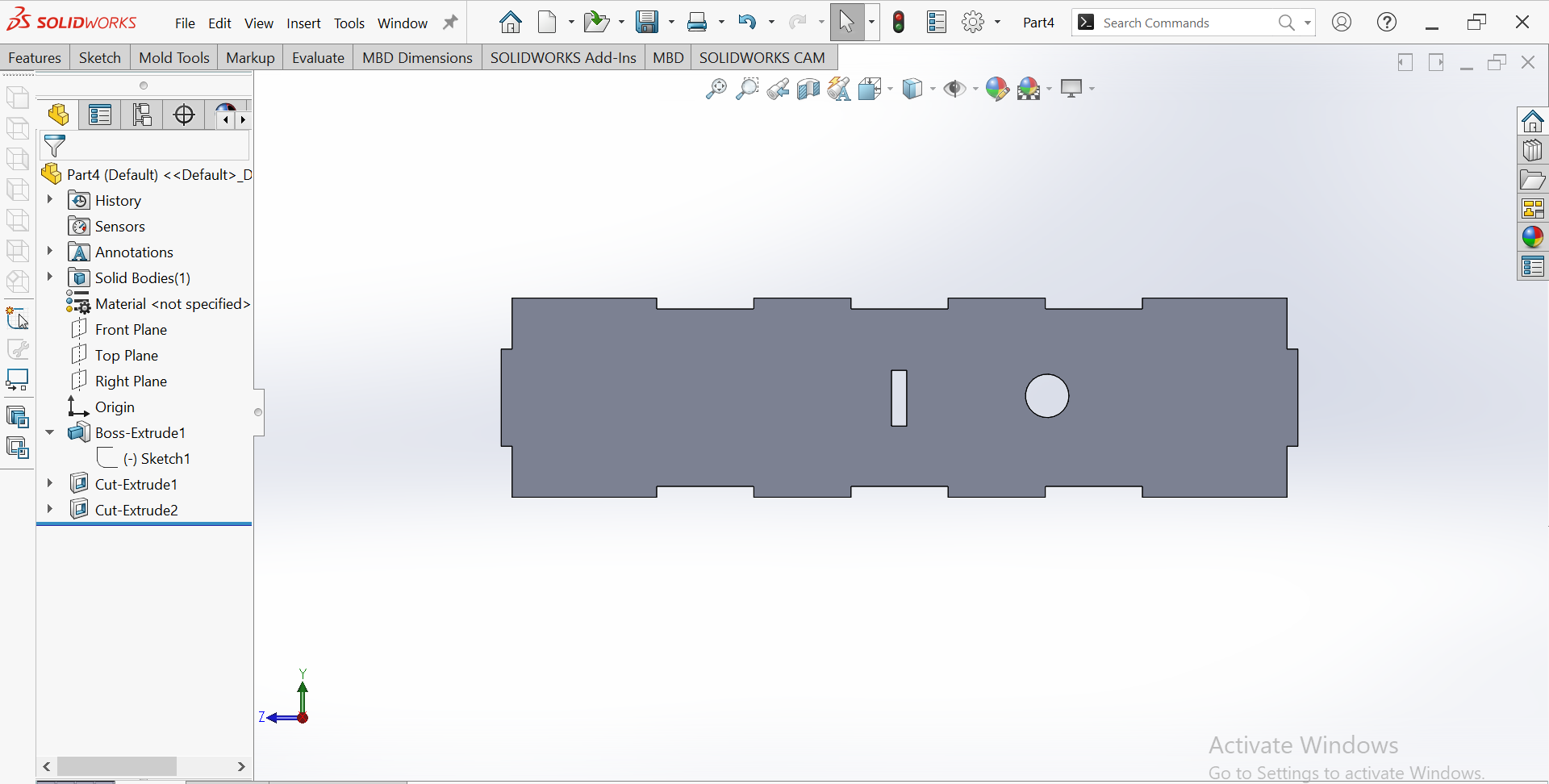
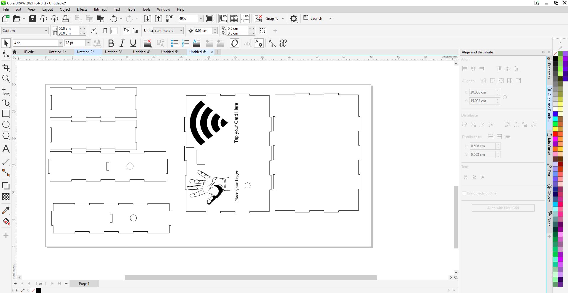
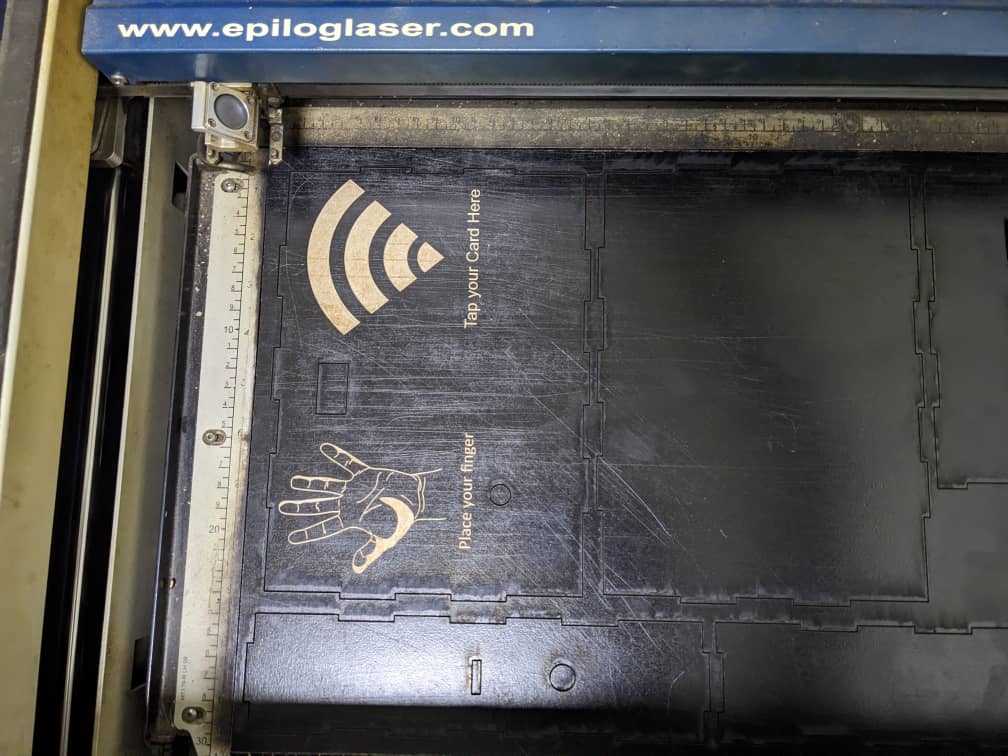
Box cutting witj laser
Backend(Server side ) Development
To build my server side code, i preferably prefer to use javascript as my favourite programming language. javascript is powerful language for building interactive froontend applications and it is applied in many frontend frameworks like Reactjs and Angularjs and many more
Javascript can be used in backend application with nodejs which i will use along with its powerful backend web application develoment framework called expressjs
System Archtecture
The above image illustate the high level archtecture of the system . The hardware device is the microcintroller which has an RFID Reader and infrared temperature sensor to sense user temperature before granting or denying acess to the given facility The system has two parts: hardware device and server side . the hardware is the microcintroller which takes user temperatur . For this case i take hand temperature and tag ID and send to the remote server. the server receives the request and make queries against the database to verify the existance of the user in the database. if the user is registered and has a normal temperature, the server reply with Access is granted and record the data. If the user is registered with Abnormal temperature The server reply with denied access and record the data If the user is not registerd , his temperature is only shown on LCD screen and the access is automatically denied for the requested access
Device request type
The request from the sensor node is a http request that has Tag Id and User current temperature in the body. so what we have to do is to make an endpoint in the server to receive the request and process it according to the received temperature and user registration status
The following is the code snippet that send a http request in Arduino to the given server endpoint
    //check if the wifi is connected now
              if(WiFi.status() == WL_CONNECTED){
               //send the web request now and check if the result is processed
                HTTPClient http;
                WiFiClient wifiClient;
                // configure traged server and url
                //http.begin("https://192.168.1.12/test.html", "7a 9c f4 db 40 d3 62 5a 6e 21 bc 5c cc 66 c8 3e a1 45 59 38"); //HTTPS
                http.begin(wifiClient,"http://192.168.43.191:4005/card?rfid=" + CARD_N0 + "&temp=" + temperature); //HTTP
                Serial.print("[HTTP] GET...\n");
                // start connection and send HTTP header:
                int httpCode = http.GET();
                // httpCode will be negative on error
                if(httpCode > 0) {
                    // HTTP header has been send and Server response header has been handled
                    //Serial.printf("[HTTP] GET... code: %d\n", httpCode);

                    // file found at server
                    if(httpCode == HTTP_CODE_OK) {
                      String payload = http.getString();
                      Serial.println(payload);

                      }
            } else {
                    Serial.printf("[HTTP] GET... failed, error: %s\n", http.errorToString(httpCode).c_str());

                }
              } else{
                  Serial.println("No WiFi Avaialable Now!!!!!");


                }
This code snippet checks if the WiFi connection is established and if it is connected, it sends an HTTP GET request to a web server to fetch data. It uses the WiFiClient library to establish a connection with the server and the HTTPClient library to send an HTTP GET request. The response from the server is stored in the payload variable. If the HTTP response code is HTTP_CODE_OK, it means that the server has responded with a success code and the payload is printed on the serial monitor. If the connection or request fails, an appropriate error message is displayed on the serial monitor.
here we send the card number which rfid tag number of user and its taken temperature to the server
the full arduino code for the device can be downlaoded here
To send a request to the server we need to know the server Url, port and endpoint that handles the request
For our case we have the following
- Server ip: 192.168.43.91
- Port: 4005
- Endpoint: /card
- Query parameters: {rfid ,temp }
- Request type: GET
When the request type from sensor node is known, then we can build the backend to handle device request
Mongodb database and User Data Model

MongoDB is a popular NoSQL document-oriented database management system, and there are several reasons why it has gained such widespread popularity:
- Flexible data model: MongoDB's document-based data model allows for flexible schema design, which means that data can be stored in a way that is more natural to the application.
- Scalability: MongoDB's architecture is designed to scale horizontally, which means that it can handle large amounts of data and high traffic loads.
- Performance: MongoDB is known for its fast read and write performance. Its indexing capabilities, automatic sharding, and in-memory storage engine contribute to its ability to handle large workloads.
- Open source: MongoDB is an open-source database, which means that it is free to use, and its source code is available for inspection and modification.
- Community support: MongoDB has a large and active community of developers and users who provide support, share knowledge, and contribute to the development of the platform.
- Cloud integration: MongoDB has strong integration with cloud platforms like AWS, Azure, and Google Cloud, making it easy to deploy and manage in the cloud.
for this system , it easier for me to use mogodb database because it is even easier to find cloud free mongodb tiers available for free like Mongodb atlas and
The system will only have two tables . one for user table and other one to hold user transactions
User Schema
     const userSchema = new Schema ({
      firstname: { type: String},
      lastname: { type: String},
       Department:{type:String}
       Post:{type:String}
       NID: { type: String},
       District: { type: String},
       Sector: { type: String},
       Cell: { type: String},
       Village: { type: String},
       Phone: { type: String},
       card: { type: String, required:true },
     });
Transaction schema
    const TranSchema = new Schema({
      firstname: { type: String},
      lastname: { type: String},
      Department:{type:String}
      Post:{type:String}
      NID: { type: String},
      District: { type: String},
      Sector: { type: String},
      Cell: { type: String},
      Village: { type: String},
      Phone: { type: String},
      card: { type: String, required:true },
      temperature: { type: Number},
      status: { type: String},
      time: { type: String},
    });
Once we know the data model. we can proceed with the backend Development of our APIs that will handle client request
to make the API , i have used expressjs which is a javascript framework to build flexible and scalable backend apps.
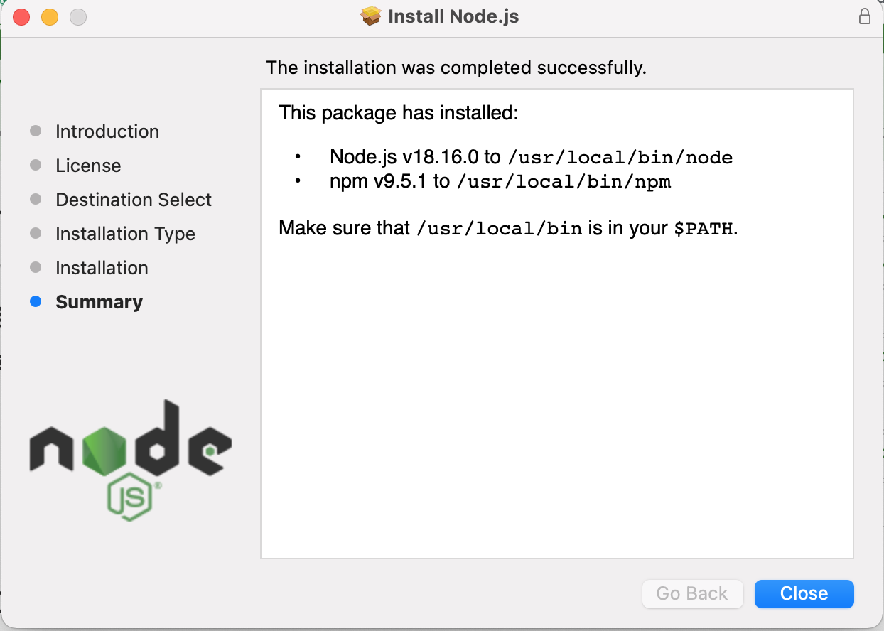
I had previous backend experience using expressjs and it was not a big proble for me . to be able to use express , we have to install nodejs in your system .
it is As an asynchronous event-driven JavaScript runtime, Node.js is designed to build scalable network applications.
it available for mac, windows and linux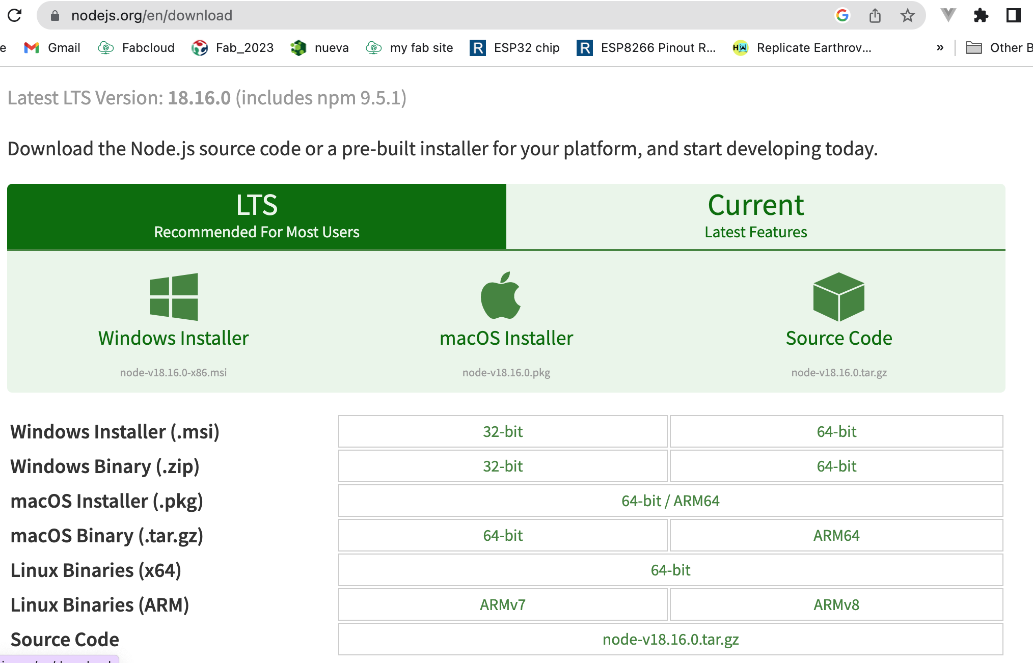
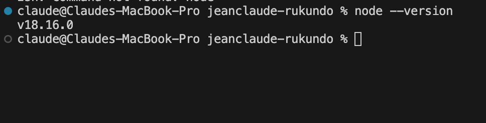
when nodejs is installed we have to check its version in your system termonal by typing the following code
node --version
To initialize a Node.js project, follow these steps:
- Open a terminal or command prompt and navigate to the directory where you want to create your project.
- Run the following command to initialize a new Node.js project using npm (Node Package Manager):
npm initThis command will prompt you with a series of questions to set up your project. You can choose to accept the default values by pressing enter for each question, or you can provide your own answers.
Once you have answered all the questions, npm will generate a package.json file in your project directory. This file contains metadata about your project, such as its name, version, dependencies, and scripts.
You can now install any dependencies that your project requires using the npm install command followed by the package name. For example, to install the Express framework, run the following command:
npm install expressThis will install the latest version of Express and update your package.json file with the dependency.
That's it! You have now successfully initialized a new Node.js project and installed a package dependency.
Here is a basic example of an Express.js server that listens for requests on port 3000:
The full backend code can be downlaoded here and it is developed in nodejs with expressjs
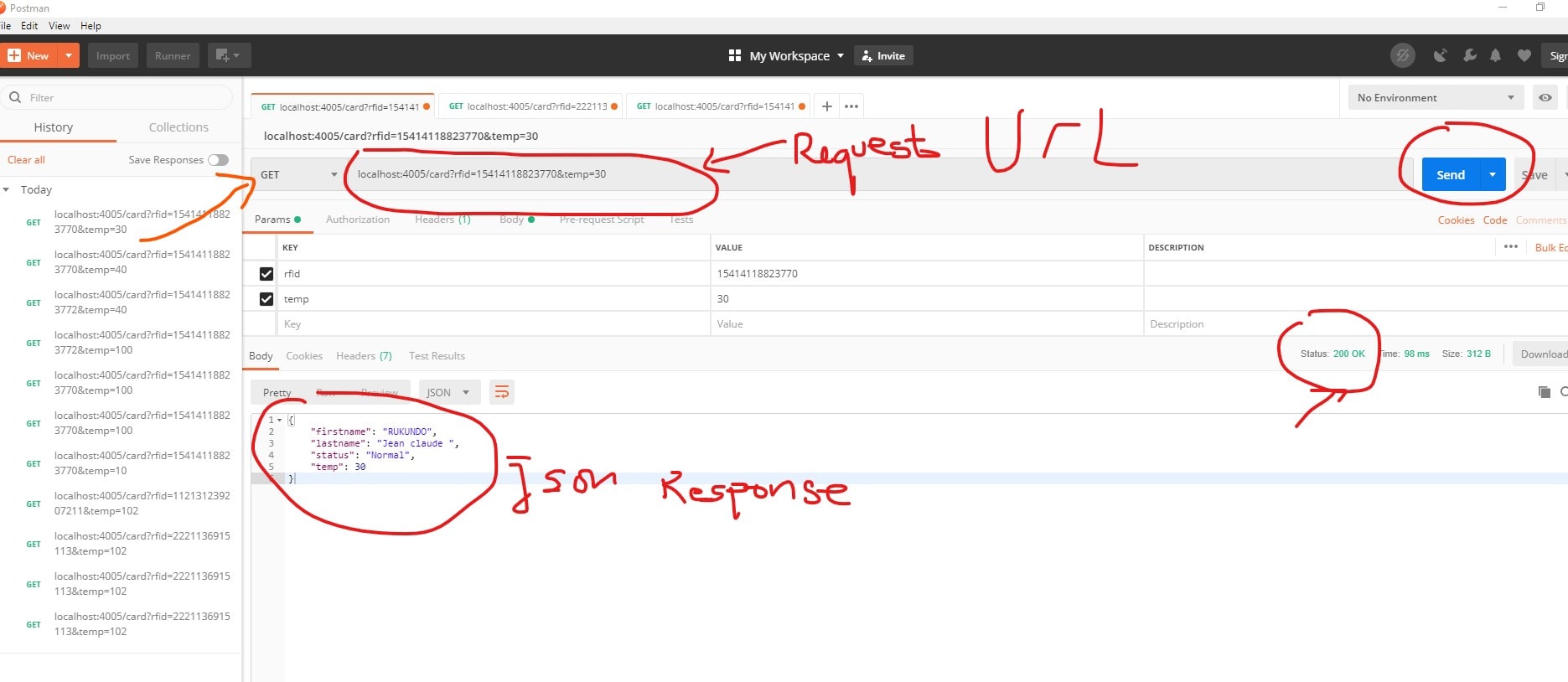
BACKEND API TESTING WITH POSTMAN
Postman API Testing Tool is a popular software application used by developers, testers, and API providers to test, document, and collaborate on APIs (Application Programming Interfaces). It provides a user-friendly interface that allows users to create and send HTTP requests, analyze responses, and validate API endpoints.
downlaod postman and install it via this web site
I have a backend built but the device code is not yet complete. i have to test my backend refering to the reuest type from the device and the request type was demonstrated above .
http request from the device looks like the following
    http.begin(wifiClient,"http://192.168.43.191:4005/card?rfid=" + CARD_N0 + "&temp=" + temperature); //HTTP
    Serial.print("[HTTP] GET...\n");
    // start connection and send HTTP header:
    int httpCode = http.GET();
Now lets test the API with a postman.
Request and response from Un-registered User
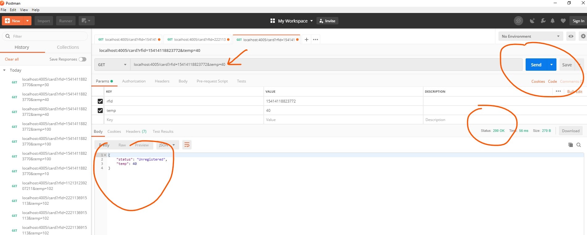
Request and response from Registered User with Normal Temperature
Request and response from Registered User with Abnormal Temperature Above 37 degrees
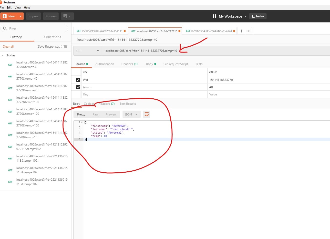
The API looks like working perfectly and the remaining is to mke a device that do the request to the API and see the system come into real life......
Frontend App development
the frontend is made with express handlebars
Handlebars.js is a templating engine similar to the ejs module in node.js, but more powerful and simple to use. It ensures minimum templating and is a logicless engine that keeps the view and the code separated. It can be used with express as the hbs module, available through npm. HandleBars can be used to render web pages to the client side from data on the server side.
Command to install hbs module:
npm i hbs
To use handlebars in express, we need to store HTML code into a .hbs extension in the ‘views’ folder in the source directory as hbs looks for the pages in the views folder. The first thing we need to do in the index.js file is to require the hbs module
        const express = require('express')
        const hbs = require('hbs')
        const app = express()
Now, we need to change the default view engine.
app.set('view engine', 'hbs')
In case the views directory is undesirable, you can change the view path by the following command:
app.set('views', )
Now, we render our webpage index.hmtl through express to the local server.
            app.get('/', (req, res) => {
              res.render('index.html')
            })

            app.listen(3000);
this is how i am rendering my html files to the frontend within the express server . mode details on how to use handlebars , please visit handlebars official site
Final Frontend App Testing with
Using postman, i have been able to create users and make random request to the API and test all functionlities needed and i bult frontend to work with the API.
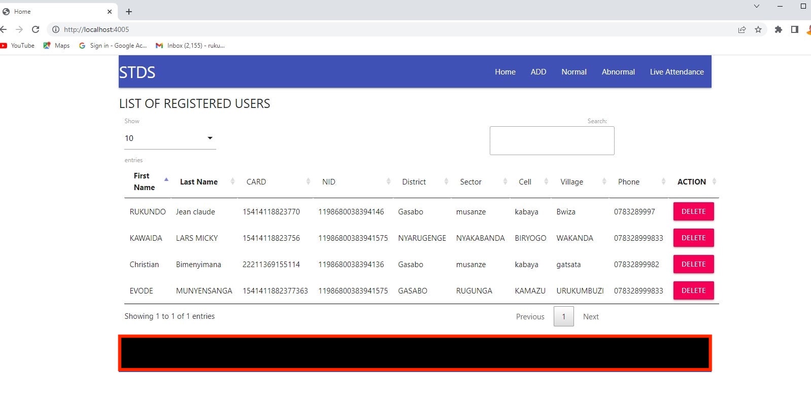
Home Page with Registered Users
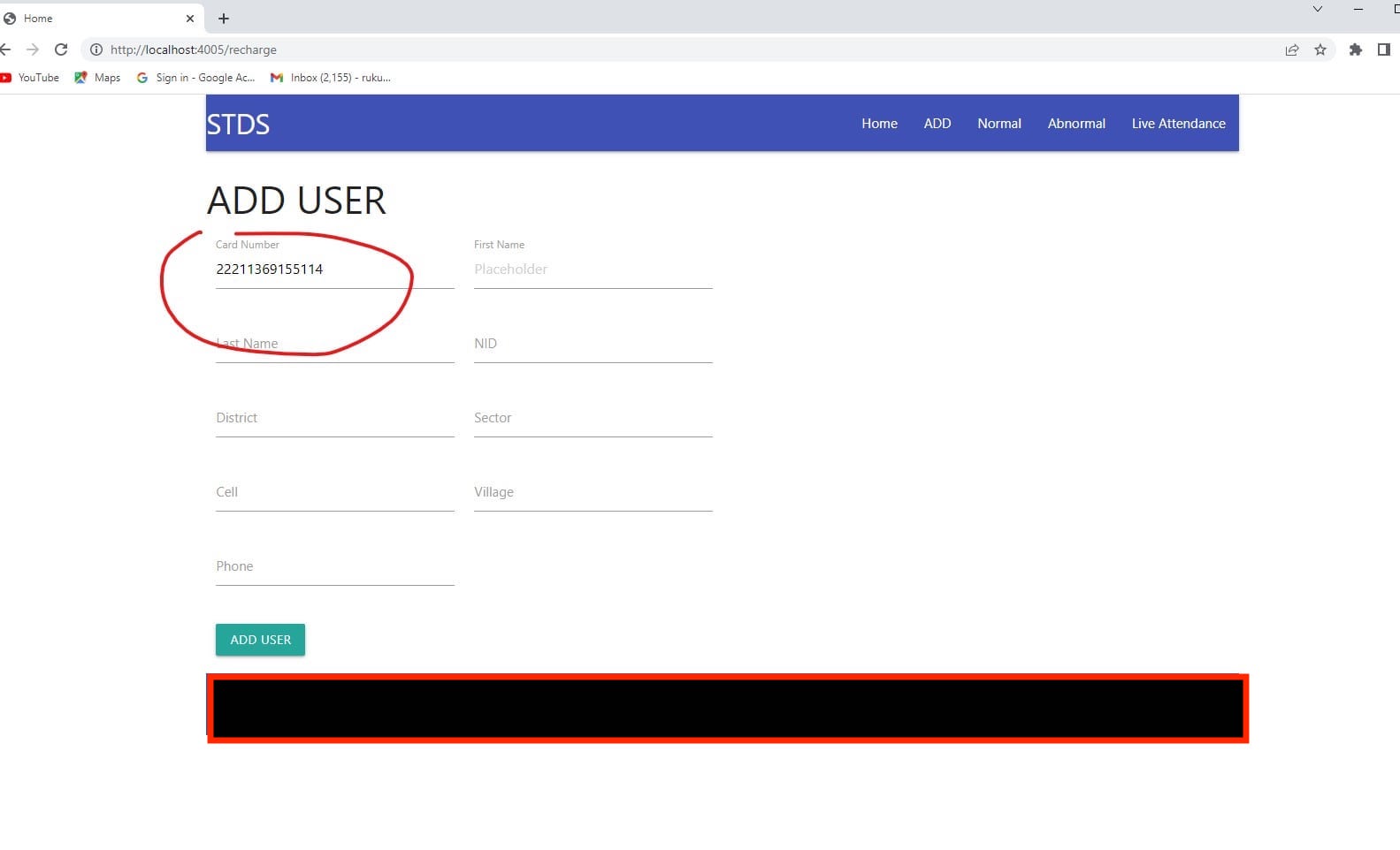
ADDING USERS THROUGH UI
you can just add users by tapping your card to rfid reader and the tag appears directly in the field and then you add other user details
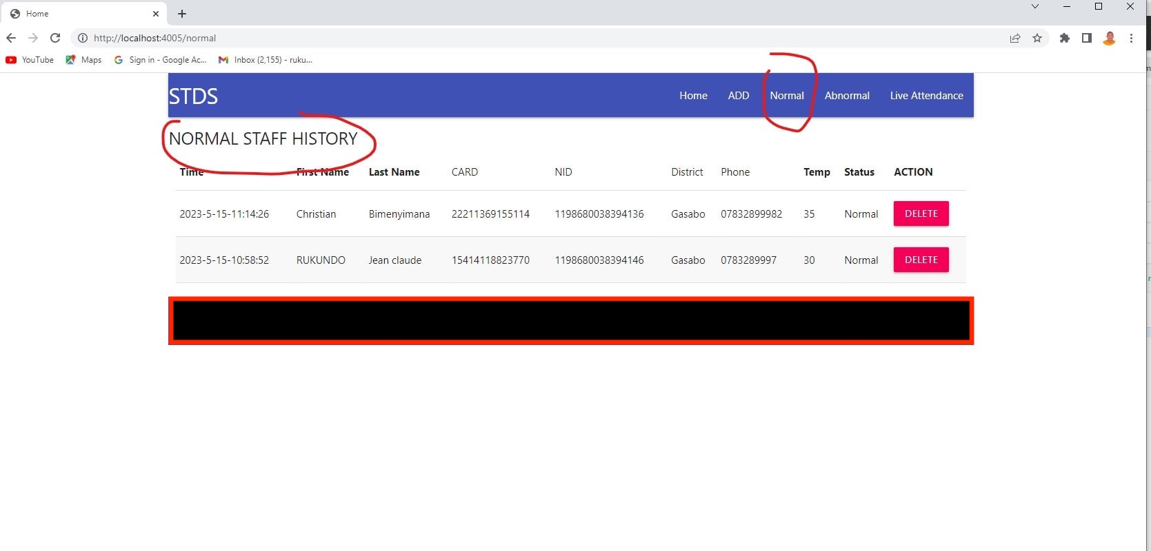
VIEW NORMAL STAFF TEMPERATURE
Click on normal link to get the list of normal staff temperature with temperature below the threshold of 37 celcius degrees
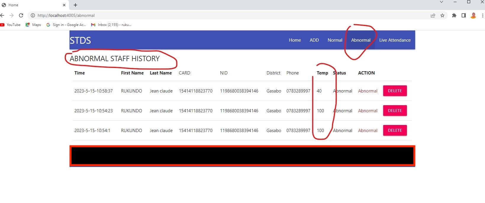
VIEW ABNORMAL STAFF TEMPERATURE
Click on Anormal link to get the list of normal staff temperature with temperature above the threshold of 37 celcius degrees
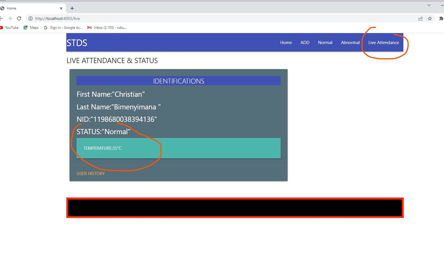
LIFE VIEW OF USERS WHO NEED ACCESS
Click on Live attendance link to see live view as users taps on the rfid reader to seek for access
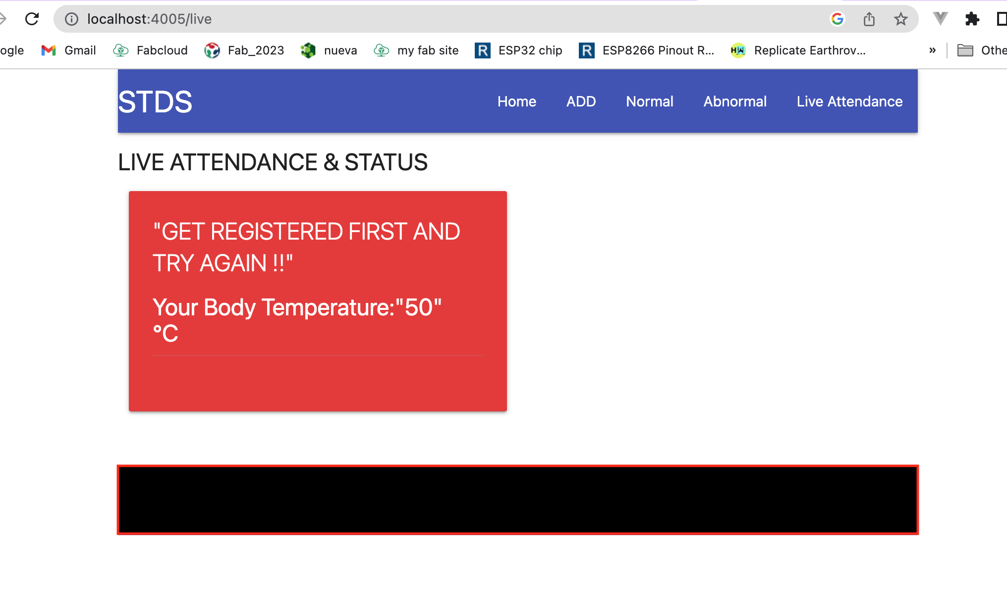
SOMEONE NOT REGISTERD AND HAVING ABNORMAL TEMPERATURE
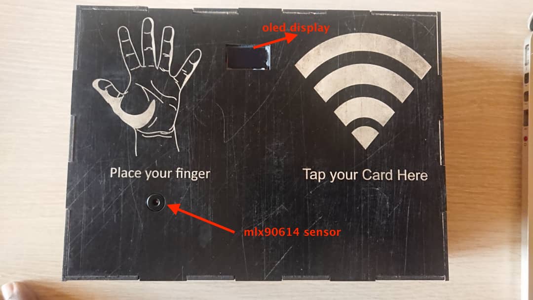
Final Project atfer implementation
Cutting Door Frame and Making final Door Lock System