Week 11: INPUT DEVICES

Group Assignment
- Measure the power consumption of an output device
Individual Assignment
- Add an output device to a microcontroller board you've designed, and program it to do something
WEEK 11 WORK ORGANIZATION
Group assignmenet
Connecting a probe to the device iunder testing is demonstared on this Group website of fablab Rwandathe process shows how to visualize sensor signals using oscilloscope and multimeter .this has showed me how sensor output voltage variation if it is analog or output digital signal if it is a digital signal
Introduction Input Devices
An input device for a microcontroller is any device or sensor that can provide data or signals to the microcontroller. Examples of input devices for microcontrollers include:
| Sensor | Working Principle |
|---|---|
| Temperature sensors | These sensors work by detecting changes in temperature through a change in resistance, voltage, or current. |
| Light sensors | These sensors work by converting light energy into an electrical signal, which can be measured by a microcontroller. There are several types of light sensors, including photodiodes, phototransistors, and photoresistors. |
| Accelerometers | These sensors measure acceleration or changes in motion by detecting changes in capacitance or piezoelectric voltage. |
| Gyroscopes | These sensors measure changes in rotational motion by detecting changes in angular velocity. |
| Magnetometers | These sensors measure magnetic fields by detecting changes in resistance or voltage. |
| Proximity sensors | These sensors work by detecting the presence or absence of an object using infrared, ultrasonic, or electromagnetic fields. |
| Pressure sensors | These sensors measure changes in pressure using various methods, including piezoresistive, capacitive, and resonant techniques. |
| Humidity sensors | These sensors measure changes in humidity by detecting changes in capacitance, resistance, or the dielectric constant of a material. |
| Gas sensors | These sensors detect changes in the concentration of gases using various methods, including catalytic combustion, electrochemical reactions, and infrared absorption. |
| IR sensors | These sensors detect infrared radiation emitted by objects and convert it into an electrical signal that can be measured by a microcontroller. |
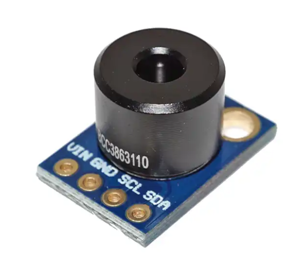
Selected Sensor: MLX90614 Infrared Temperature Sensor
The MLX90614 is a non-contact infrared thermometer sensor that can measure the temperature of an object without physically touching it. It is manufactured by Melexis, a company that produces various types of sensors for automotive, industrial, and consumer applications.
The MLX90614 uses an infrared sensitive thermopile detector chip to measure the thermal radiation emitted by an object and converts it into an electrical signal. It also contains an integrated signal conditioning chip that amplifies and filters the signal before outputting a temperature reading in degrees Celsius or Fahrenheit.
The main applications of the MLX90614 sensor include temperature sensing in various industrial processes, such as food processing, HVAC systems, and automotive applications. It is also used in medical devices for body temperature measurement, such as ear thermometers and forehead thermometers. In addition, the MLX90614 is used in consumer electronics for temperature sensing in smartphones, laptops, and other portable devices.

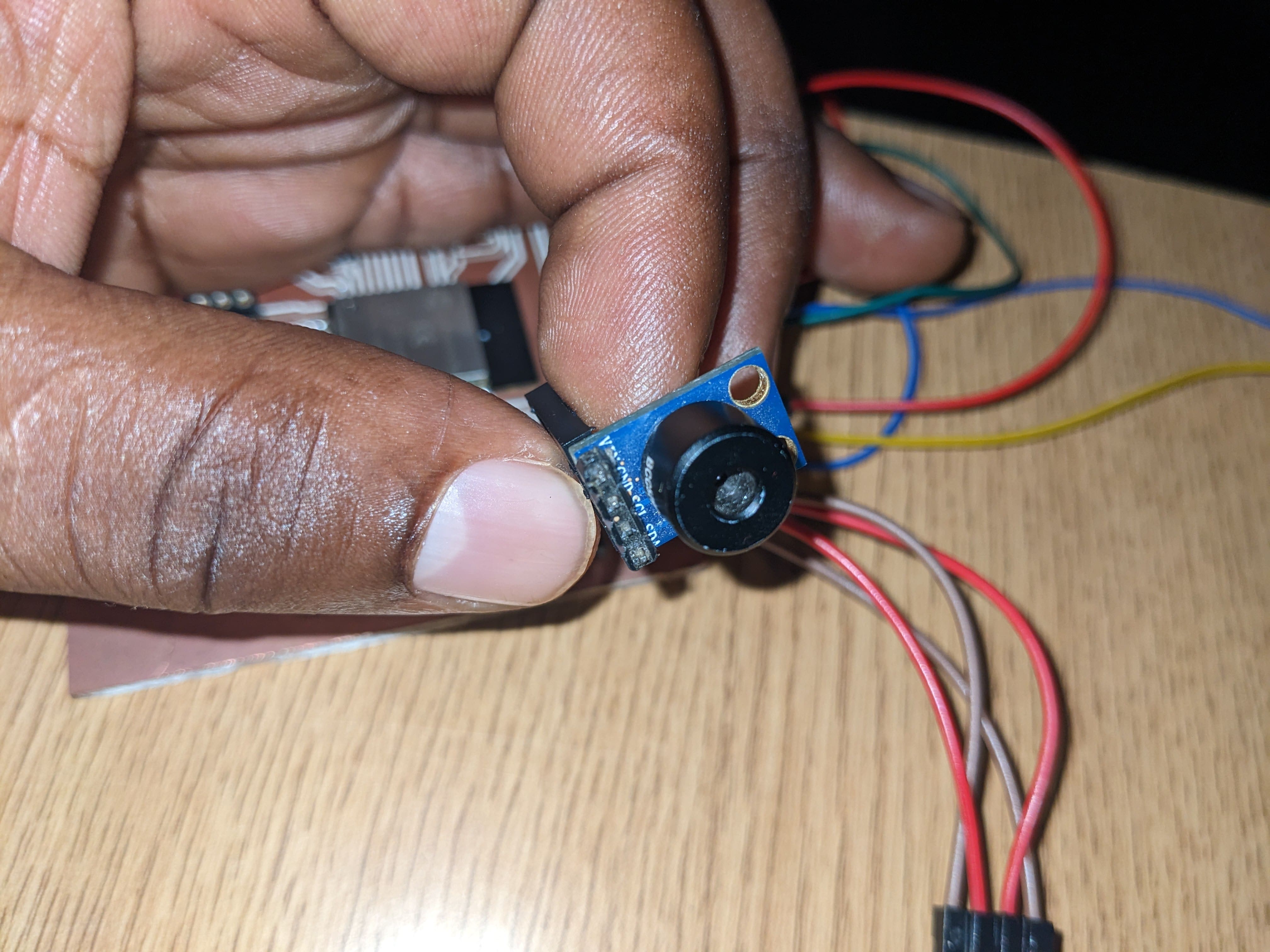
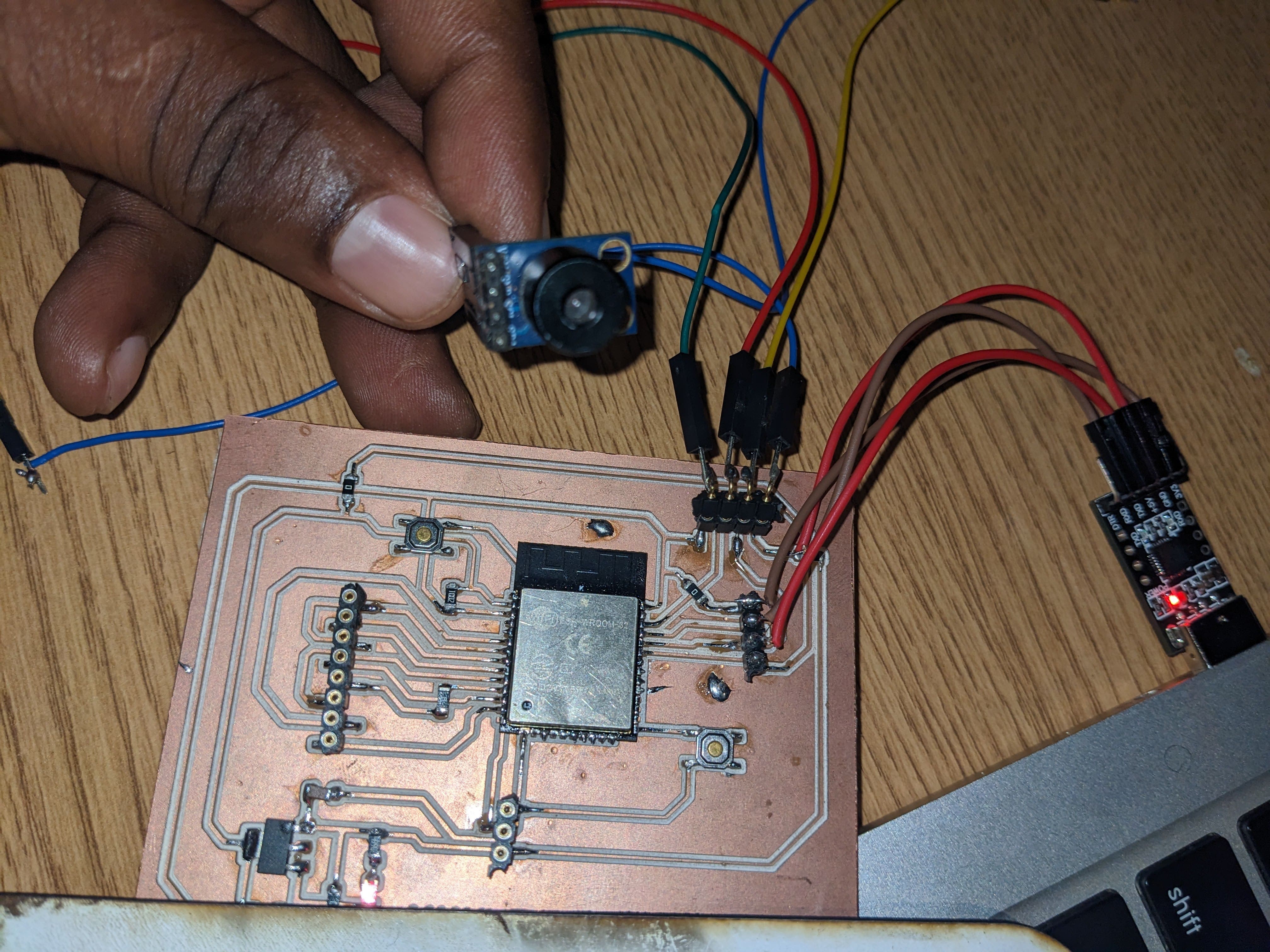
i have used the previous Board i designed on the week of output device which is esp32 Soc on PCB . the sensor uses I2C procol for data communication.
I2C (Inter-Integrated Circuit) is a serial communication protocol used for communication between microcontrollers, sensors, and other integrated circuits.
The I2C protocol uses a master-slave architecture, where the master device initiates communication with one or more slave devices on a shared bus. The communication is synchronous, meaning that data is transferred bit by bit over the bus, with a clock signal generated by the master device.
circuit diagram
The used MCU board has been build in the week of output deviced and can be seen here. I used previous pcb board as indicated in the assigment guidelines
The ESP32 microcontroller has built-in support for the I2C communication protocol, which can be implemented using its two dedicated I2C pins - GPIO21 (SDA) and GPIO22 (SCL). The SDA pin (GPIO21) is used for data transfer between the master and slave devices, while the SCL pin (GPIO22) provides the clock signal for synchronizing the data transfer. Both pins are bidirectional and support open-drain configuration with pull-up resistors, allowing for communication with multiple devices on the same bus.
i have connected SENSOR I2C pins on the pins mentioned above

Add a sensor to a microcontroller

Code
 /***************************************************
  This is a library example for the MLX90614 Temp Sensor

  These sensors use I2C to communicate, 2 pins are required to
  interface

 ****************************************************/

#include

Adafruit_MLX90614 mlx = Adafruit_MLX90614();

void setup() {
  Serial.begin(9600);
  while (!Serial);

  Serial.println("Adafruit MLX90614 test");

  if (!mlx.begin()) {
    Serial.println("Error connecting to MLX sensor. Check wiring.");
    while (1);
  };

  Serial.print("Emissivity = "); Serial.println(mlx.readEmissivity());
  Serial.println("================================================");
}

void loop() {
  Serial.print("Ambient Tempeature = "); Serial.print(mlx.readAmbientTempC());
  Serial.print(" Body Temperature= "); Serial.print(mlx.readObjectTempC()); Serial.println("*C");

  Serial.println();
  delay(2500);
}
Output
