Week 9: OUTPUT DEVICES
Group Assignment
- Measure the power consumption of an output device
Individual Assignment
- Add an output device to a microcontroller board you've designed, and program it to do something
Group assignmenet
The measurement of power consumption of a given output devices is demonstated on this Group website of fablab RwandaIntroduction to Output Devices
This week assignment was to connect the output device on the designed microcontroller circuit board already designed in week 7. on my side , i have used attinty45 in electronics design week and the pcb produced was based on attinty45 MCU. for this week i never used the same controller. i shifted to esp-WROM-32 Soc chip that has many advantages compared to attinty45 and it is what i am planning to use in my final project.
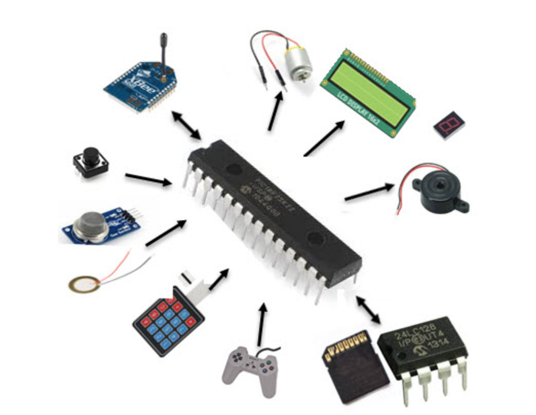
Overview of some output devices
Output devices for microcontrollers can be broadly classified into two categories: mechanical and electronic. Mechanical output devices are those that produce mechanical movement or motion, such as motors and actuators, while electronic output devices produce light or sound, such as LEDs and buzzers.
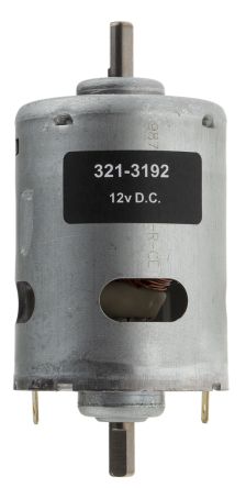
DC motors, stepper motors, and servo motors are all types of mechanical output devices commonly used with microcontrollers.
DC motors are simple motors that convert electrical energy into rotational motion. They have two terminals, and their direction of rotation
can be controlled by reversing the polarity of the applied voltage.
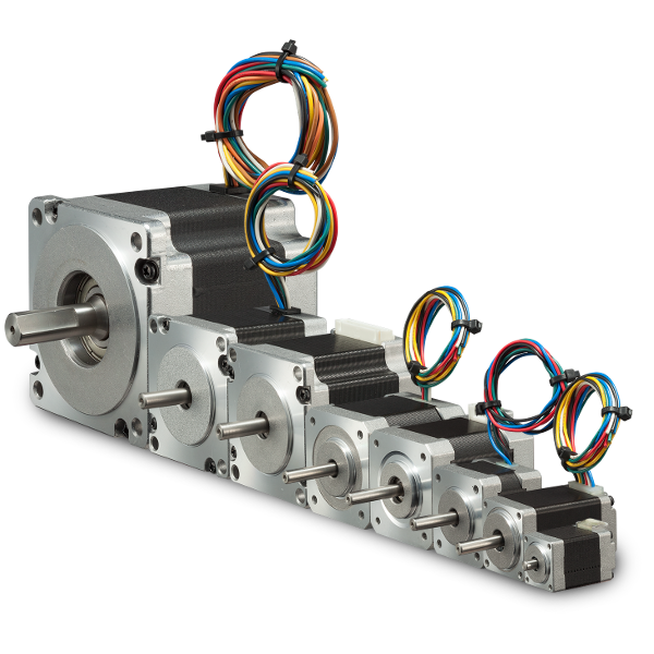
Stepper motors, on the other hand, are more complex motors that rotate in precise steps. They are often used in applications
that require accurate positioning, such as robotics and CNC machines.
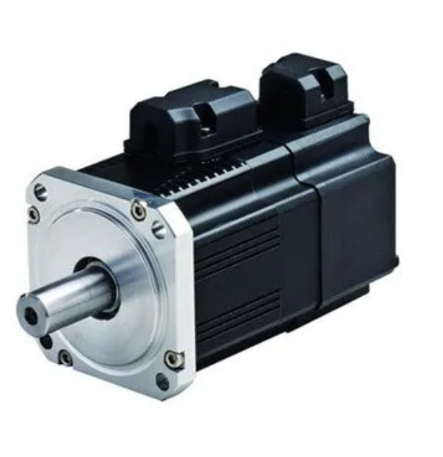
Servo motors are also precise motors, but they are designed to rotate to a specific angle rather than in continuous rotation. They are often used in applications that
require precise control, such as robotics and remote-controlled vehicles.
To use these mechanical output devices with microcontrollers, you need to connect them to the microcontroller's output pins, and then write code to control their behavior. The specific wiring and code will depend on the type of motor being used and the microcontroller being used.
Apart from motors, microcontrollers can also be connected to various electronic output devices such as LEDs, LCD screens, OLED screens, and more. These devices can be used to display information or provide visual feedback to the user.
LEDs are the most common output devices and are often used to indicate the status of a system or provide feedback to the user. They are low-cost and consume less power. They can be connected to a microcontroller's output pin directly or through a driver circuit to protect the microcontroller from damage due to excessive current. LEDs can be used to display various patterns or blink in different colors to convey specific messages to the user.
LCD screens , on the other hand, are used to display alphanumeric characters, graphics, and other information. They can be used to display the current status of a system, sensor readings, or user inputs. They require more complex driver circuits than LEDs and consume more power, but they offer a high level of customization and can display more complex information.
OLED screens are similar to LCD screens, but they offer better color reproduction, higher contrast, and faster refresh rates. They are commonly used in portable devices such as smartphones, smartwatches, and other wearable electronics. They also require more complex driver circuits, and their cost is usually higher than that of LCD screens.Choice of Microcontroller Fot the Rest of Assignment and Final Project
i have selected the esp-wrom-32 MCU for the rest of assignment including this week assignment so, i started the PCB design from scratch so that that i have baseline of my future work.
Why ESP32?
The following table that provides more detail on the performance of the ESP-WROOM-32:
| Performance | Details |
|---|---|
| Processor | Dual-core Tensilica LX6 processor, running at up to 240MHz |
| Memory | 4MB flash memory and 520KB SRAM |
| Communication Protocols | Wi-Fi 802.11 b/g/n/e/i, Bluetooth v4.2 BR/EDR and BLE, Ethernet MAC interface with dedicated DMA and IEEE 1588 support |
| Low Power Features | Advanced low-power management system including a range of power-saving modes, such as deep sleep, light sleep, and modem sleep |
| Peripherals | 12-bit SAR ADC up to 18 channels, 2 × 8-bit DACs, 10 × touch sensors, 4 × SPI, 2 × I2S, 2 × I2C, 3 × UART, 1 × SD/SDIO/MMC host controller, 1 × SPI slave, 1 × ethernet MAC interface, 1 × USB 2.0 (device/host/OTG), 1 × CAN 2.0 (Controller Area Network) |
| Operating Voltage | 2.2V to 3.6V |
The ESP-WROOM-32 is a powerful and versatile chip that can support a wide range of embedded programming applications. Its dual-core processor, ample memory, and support for multiple communication protocols make it well-suited for IoT devices, while its low-power features and advanced peripheral capabilities allow for efficient and flexible design options.
In my final project, i will be using sensors and actuators that need wifi communication and I2C pins for working. that is the reason why i shifted to esp-wrom-32 Soc Chip
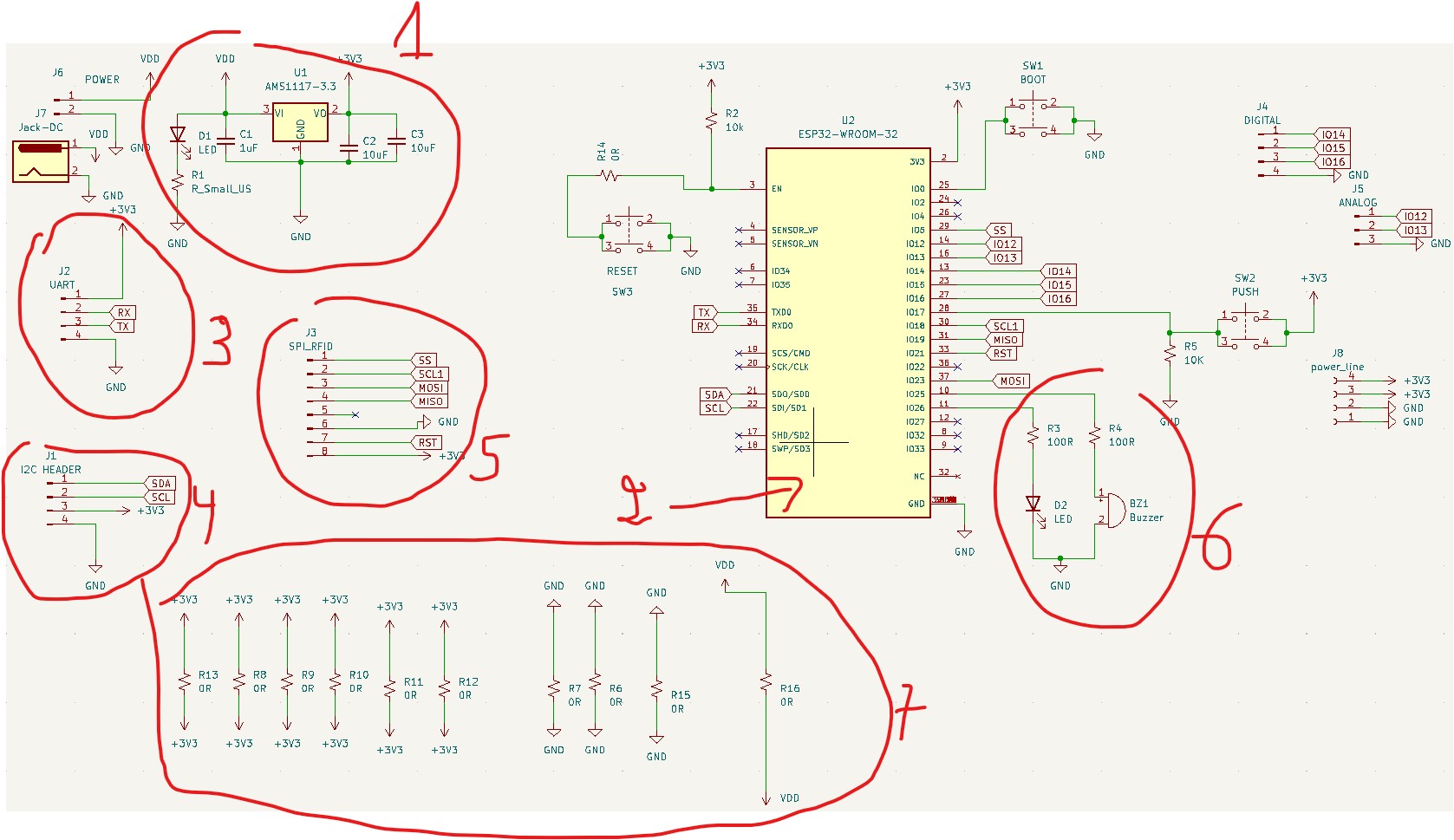
Circuit and PCB Design For Selected Mcu
i designed my circuit in kicad as i did in the week 7 assignment
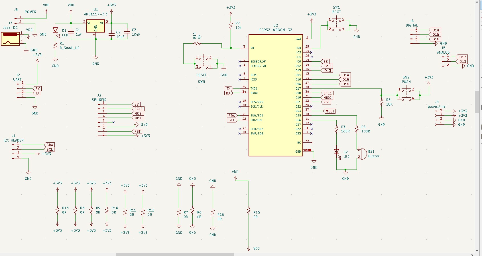
Circuit Description
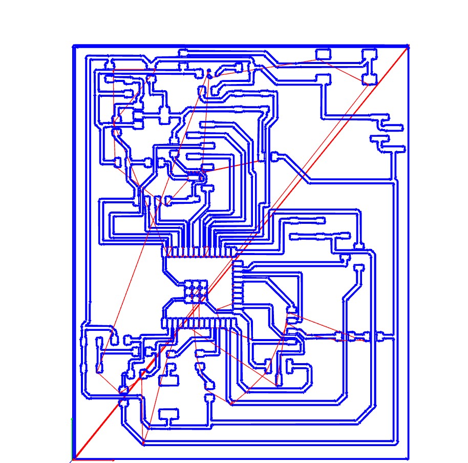
The following is The pcb routing
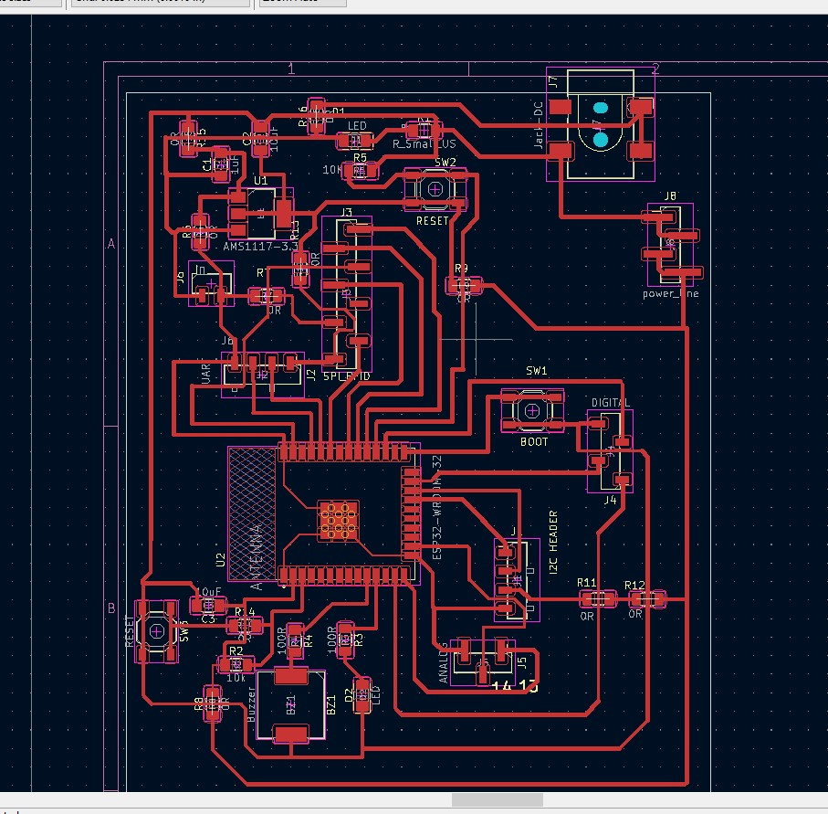
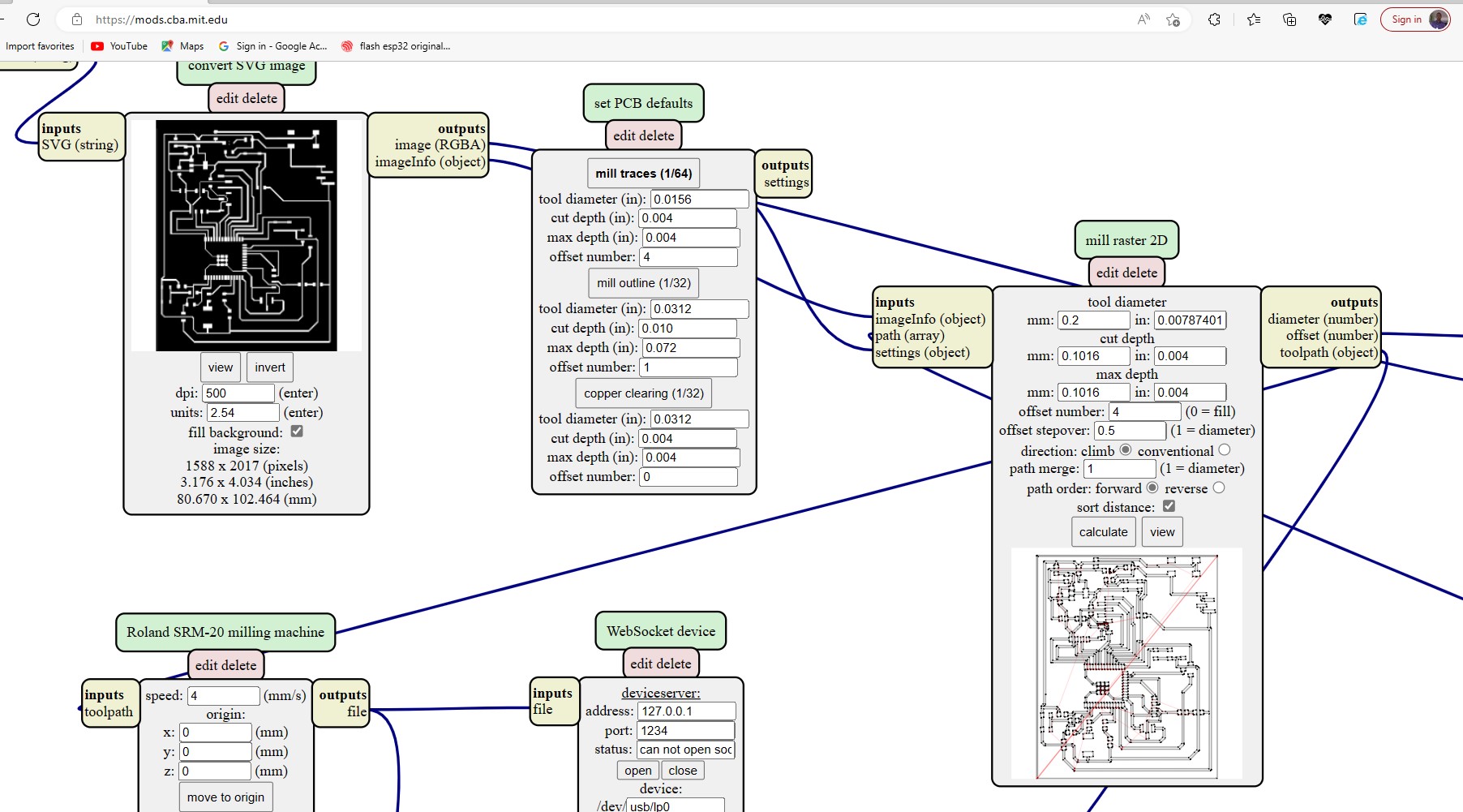
Finally i saved the pcb as png file then i used This toolto generate toolpath and G-code for the roland srm-20 milling machine that we use in fablab Rwanda
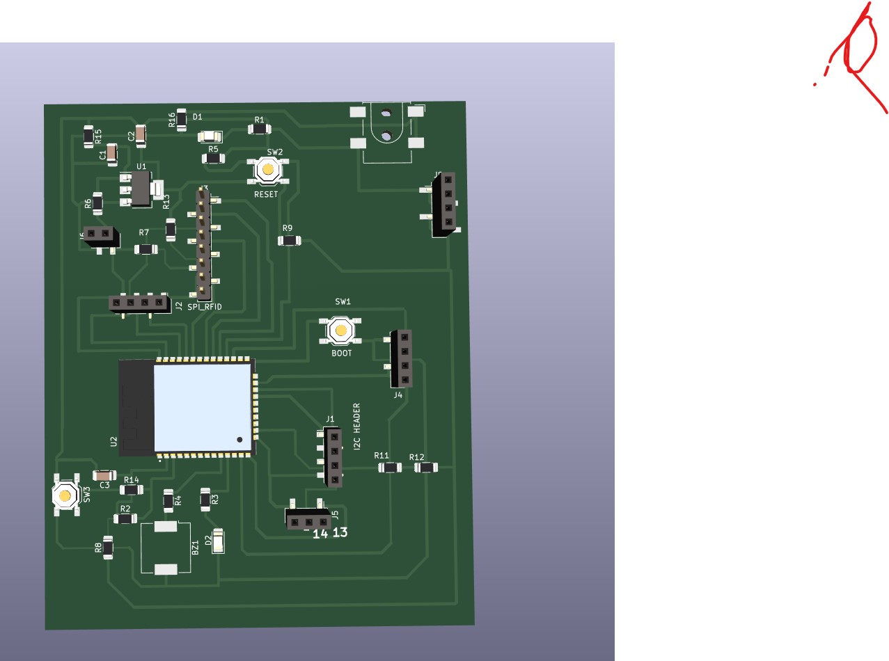
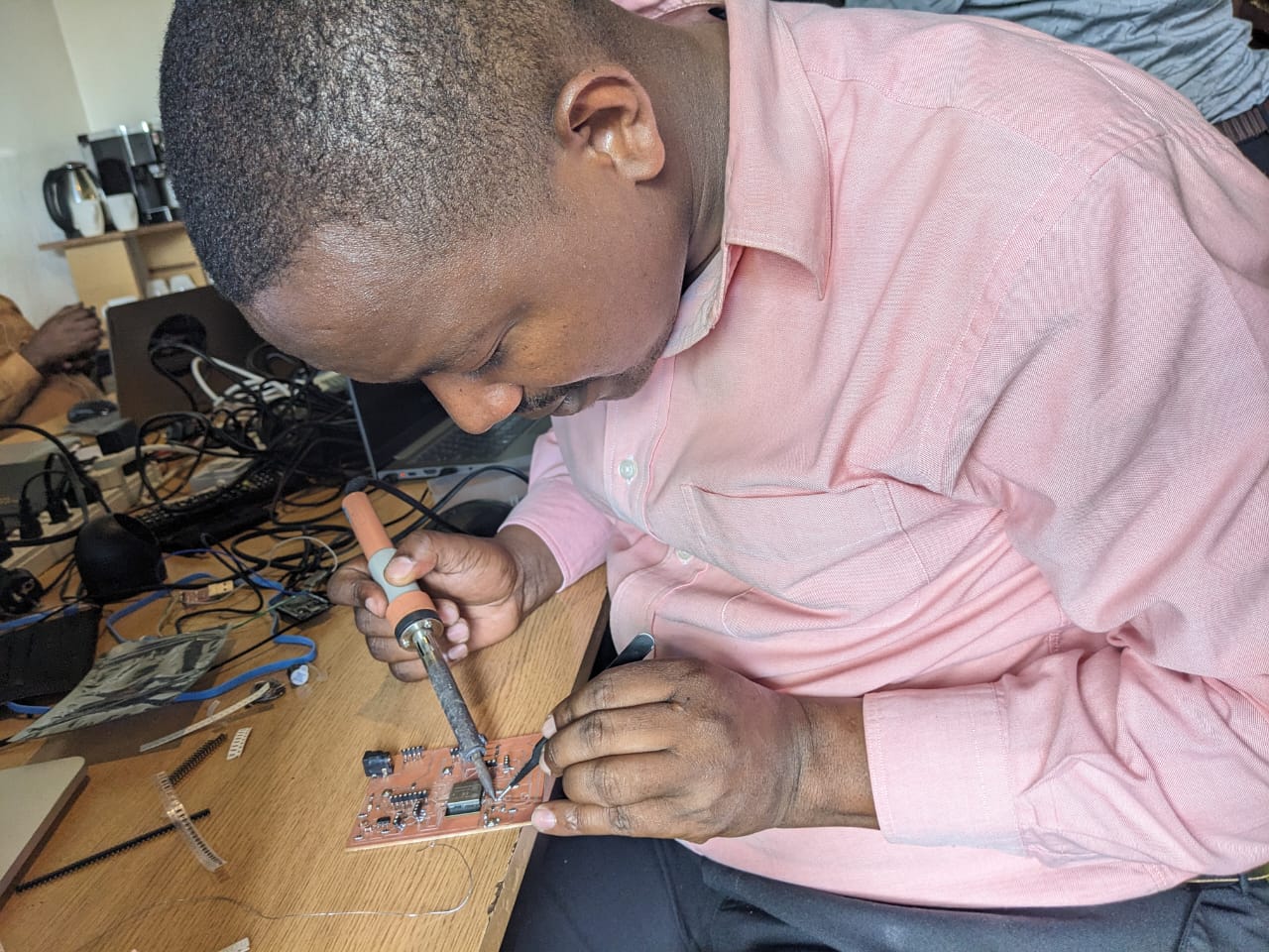
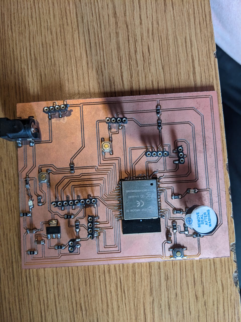
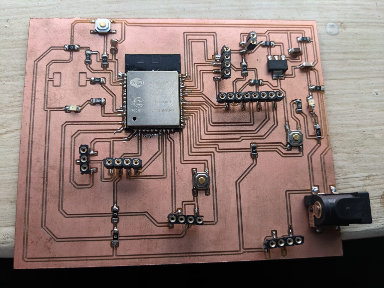
The final pcb have been milled and i started soldering components on the PCB
Soldering and Testing the Final PCB
Actually Soldering smd components seems to be complicated for me but i tried and i m getting familliar with it .
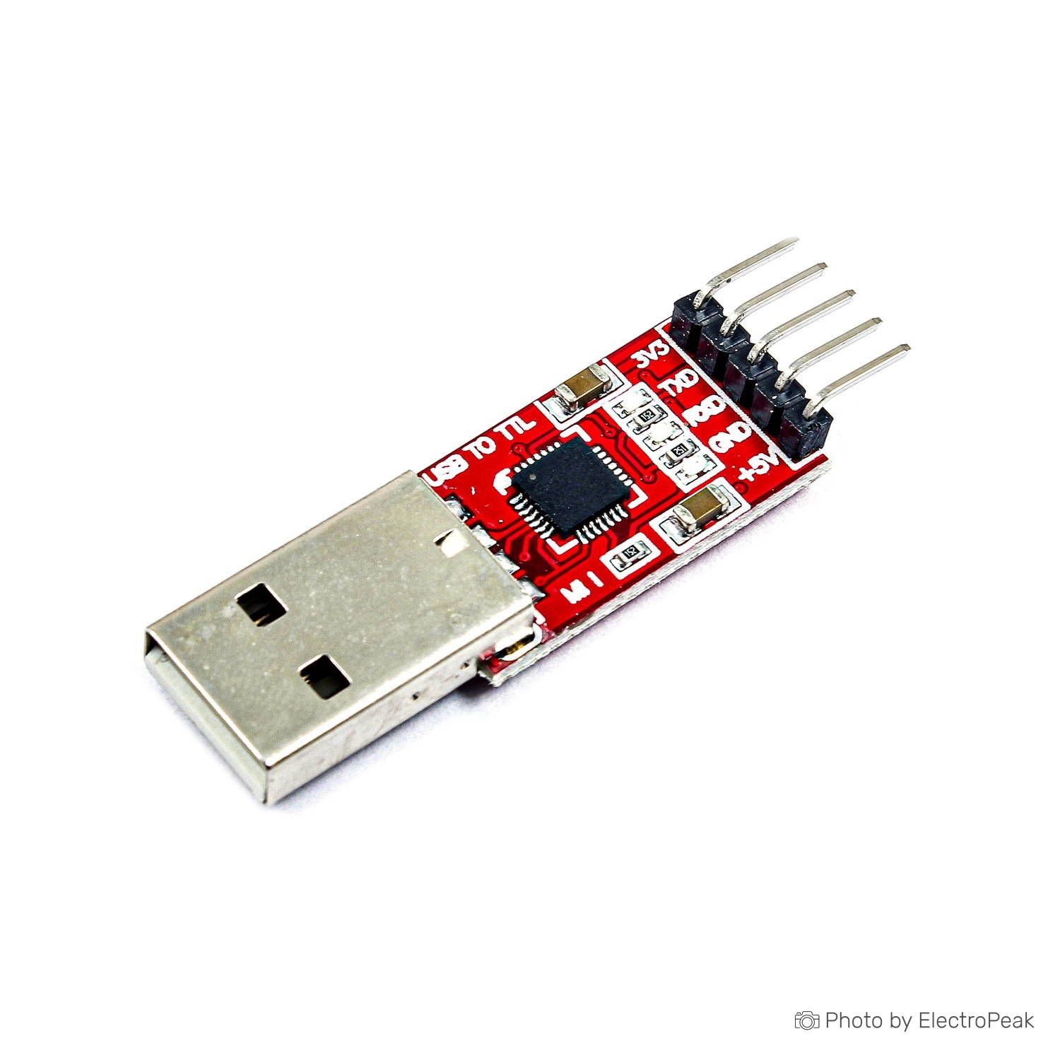
The esp-wrom-32 is 3.6 voltage operated so i have to use programmer that produce pick voltage that cannot go beyond 3.6volts . The folllowing image shows the usb to uart programmer that i used to flash code in esp-wrom-32 flash memory.
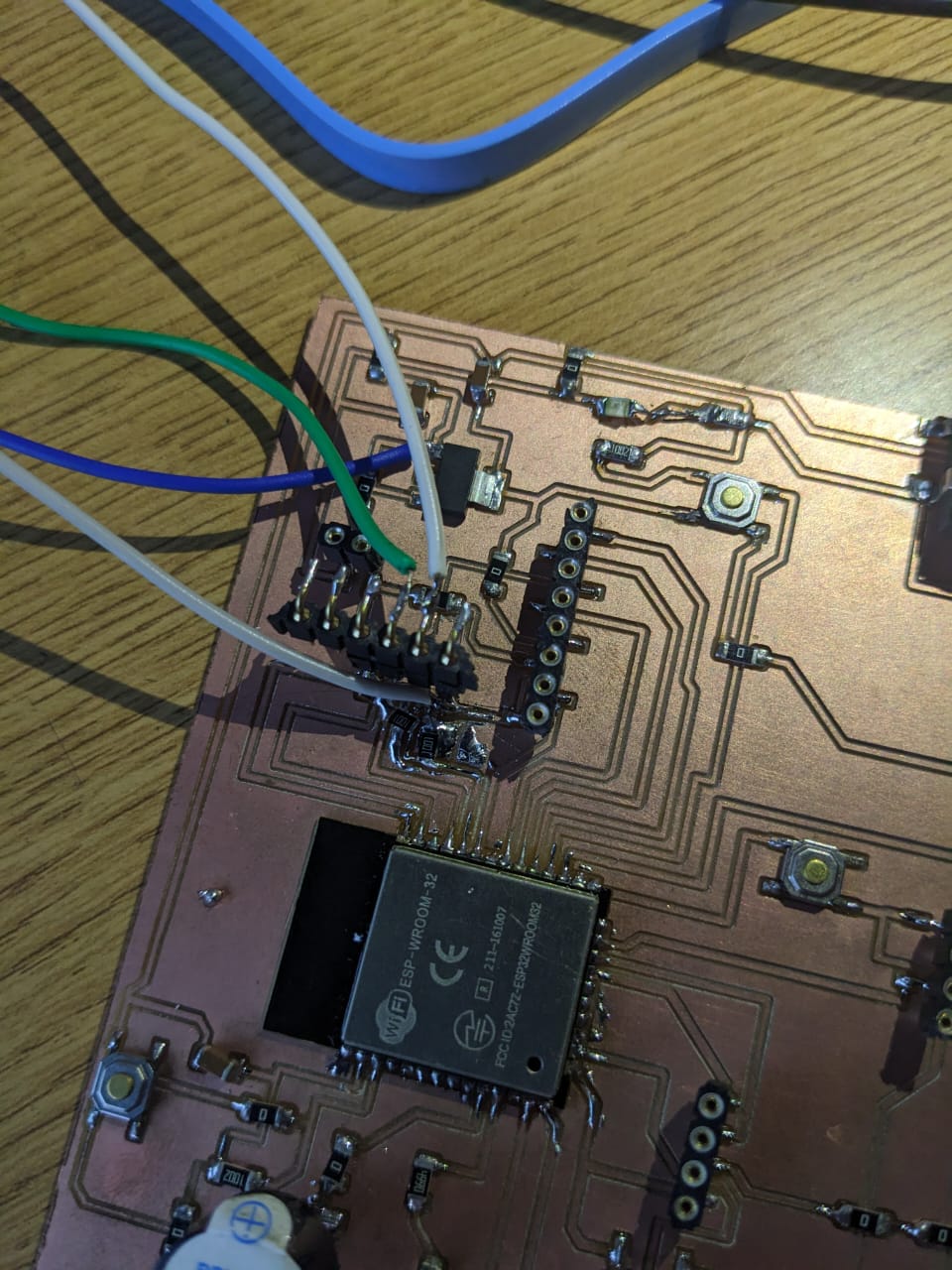
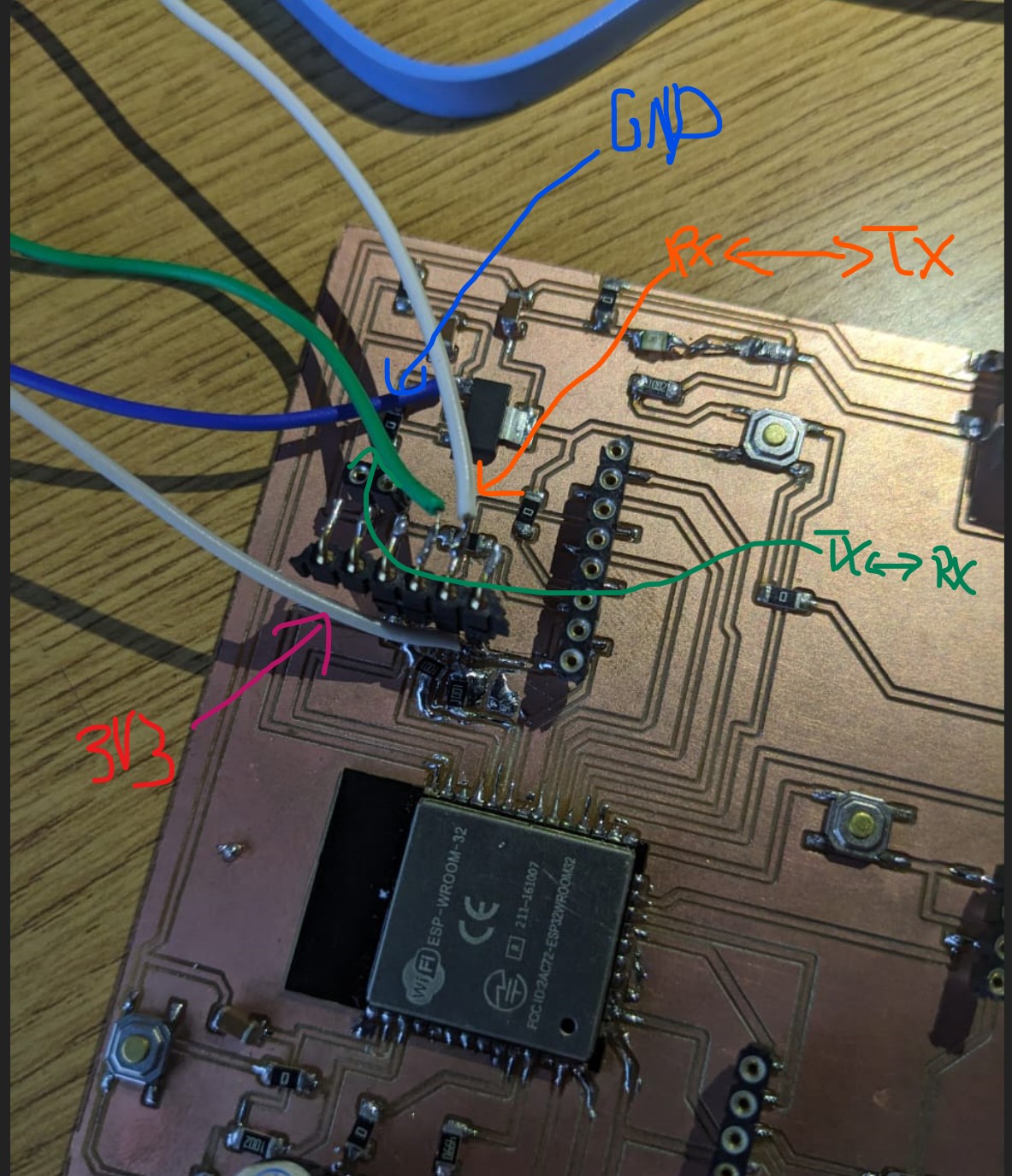
This is the way i connected my esp-wrom-32 to usb to uart bridge to be able to fire the MCU.
Programming and Connecting the Output Device.
in my circuit, the I/O PIN number 26 is connected to an LED . so i have to make an arduino program to turn it on/off. luckily, the ESP-WROM-32 IS SHIPPED WITH BOOTLOADER INSTALLED. it is not necessary to install bootlader unless it is not installed or modified.
Steps to program esp-wrom-32
here are the steps to program the ESP-WROOM-32 with a USB to UART module using the Arduino IDE:
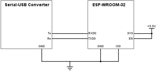
- Connect the ESP-WROOM-32 to the USB to UART module as follows:
- Connect ESP-WROOM-32 3V3 pin to USB to UART module 3V3 pin
- ESP-WROOM-32 GND pin to USB to UART module GND pin
- ESP-WROOM-32 TX pin to USB to UART module RX pin
- ESP-WROOM-32 RX pin to USB to UART module TX pin
- ESP-WROOM-32 EN pin to USB to UART module RTS pin for reset
- ESP-WROOM-32 IO0 pin to USB to UART module DTR pin for boot mode
- Download and install the Arduino IDE if you haven't already done so.
- Open the Arduino IDE and go to "File" -> "Preferences". In the "Additional Boards Manager URLs" field, enter the following URL:
- Go to "Tools" -> "Board" -> "Boards Manager". Search for "esp32" and install the "esp32" package by Espressif Systems.
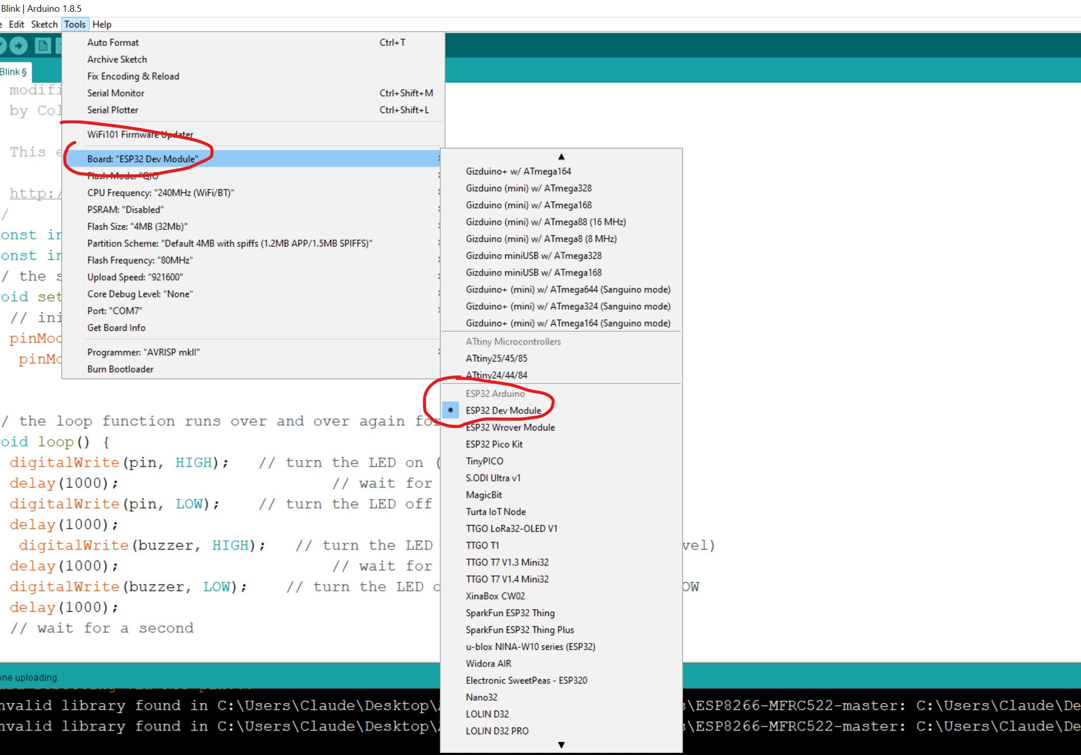
- Go to "Tools" -> "Board" and select "ESP32 Dev Module".
- Go to "Tools" -> "Port" and select the port that corresponds to the USB to UART module.
- Open the "Blink" example sketch by going to "File" -> "Examples" -> "01.Basics" -> "Blink".
- n the sketch, change the LED pin number corresponding to what you have LED attached to. in my case is 26
- Verify the sketch by clicking on the "Verify" button (checkmark icon).
- Upload the sketch by clicking on the "Upload" button (right arrow icon).
- Push on the boot button when ready to upload
- If the upload is successful, the LED on the ESP-WROOM-32 should start blinking.
https://dl.espressif.com/dl/package_esp32_index.json
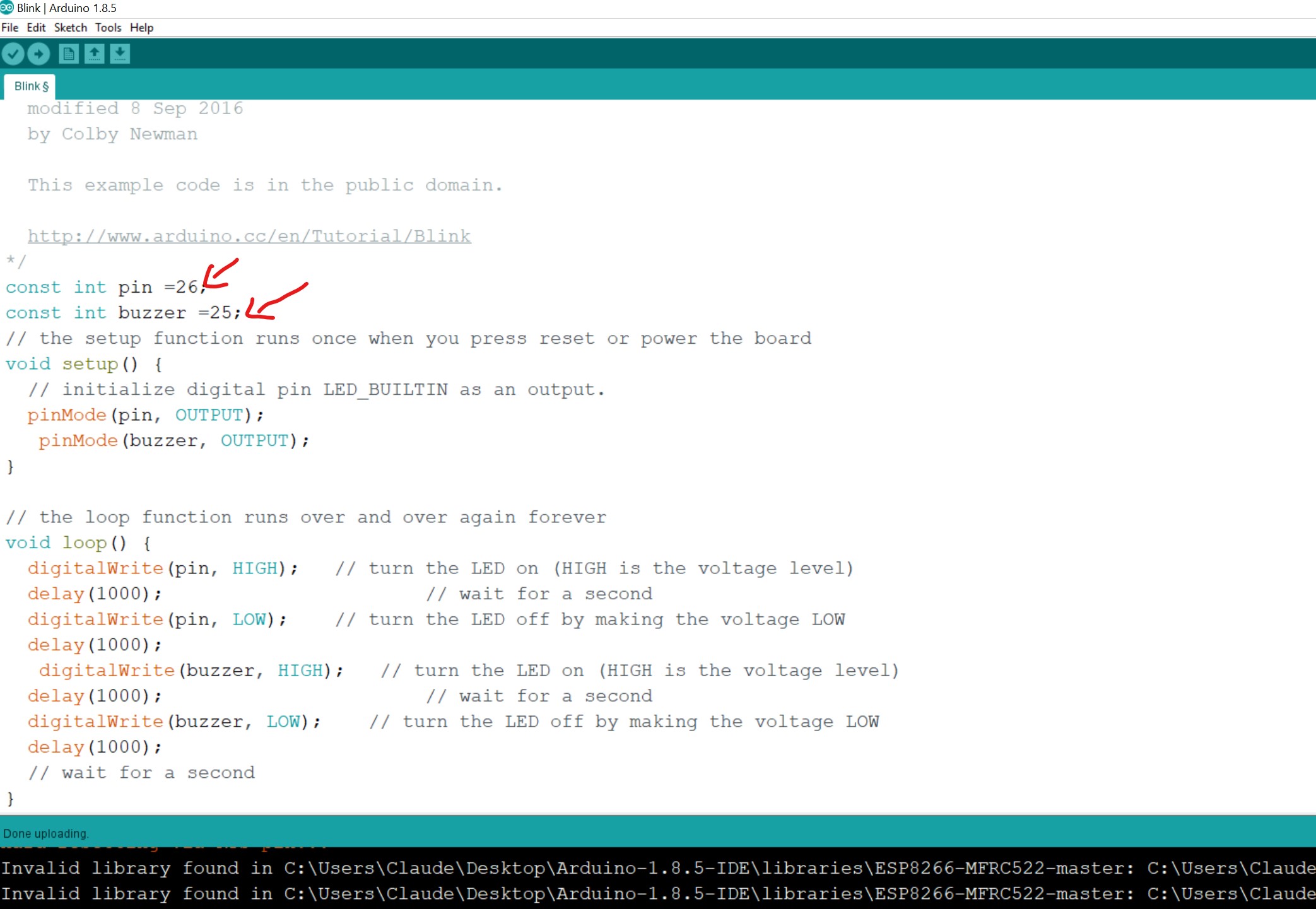
here is an Arduino code that will turn on the buzzer and LED on the ESP32 Dev Module for 1 second and then turn them off for 1 second, respectively:
        // Pin Definitions
        const int BUZZER_PIN = 25;
        const int LED_PIN = 26;

        // Setup function
        void setup() {
          // Initialize the buzzer and LED pins
          pinMode(BUZZER_PIN, OUTPUT);
          pinMode(LED_PIN, OUTPUT);
        }

        // Loop function
        void loop() {
          // Turn on the buzzer and LED
          digitalWrite(BUZZER_PIN, HIGH);
          digitalWrite(LED_PIN, HIGH);
          delay(1000); // wait for 1 second

          // Turn off the buzzer and LED
          digitalWrite(BUZZER_PIN, LOW);
          digitalWrite(LED_PIN, LOW);
          delay(1000); // wait for 1 second
        }
In this code, we first define the pin numbers for the buzzer and LED as constants. In the setup() function, we set the pin modes for these pins as OUTPUT.
In the loop() function, we first turn on the buzzer and LED by setting their corresponding pins to HIGH. We then wait for 1 second using the delay() function.
After the 1 second delay, we turn off the buzzer and LED by setting their corresponding pins to LOW. We then wait for another 1 second before repeating the loop.