Week 7: ELECTRONICS PRODUCTION
Group Assignment
- Characterize the design rules for your in-house PCB production process: document feeds, speeds, plunge rate, depth of cut (traces and outline) and tooling document your work (in a group or individually)
- Test runout, alignment, fixturing, speeds, feeds, materials and toolpaths for your machine
- Document your work to the group work page and reflect on your individual page what you learned
Individual Assignment
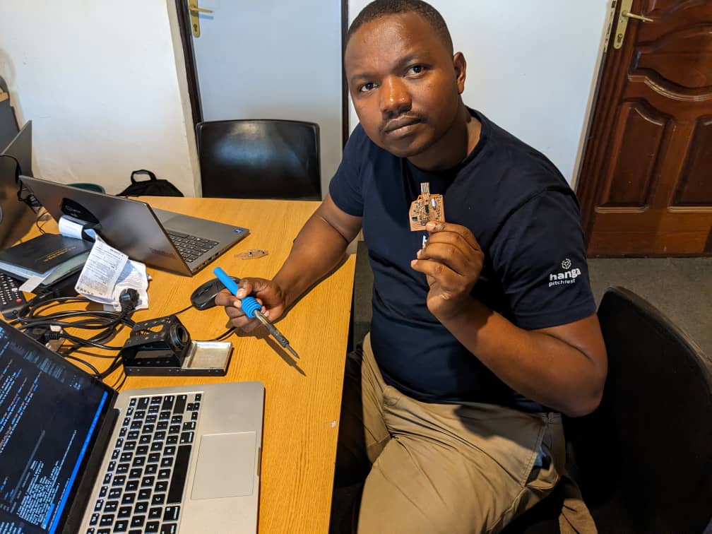
- Make and test the development board that you designed to interact and communicate with an embedded microcontroller
Makng USB to Serial AVR programmer
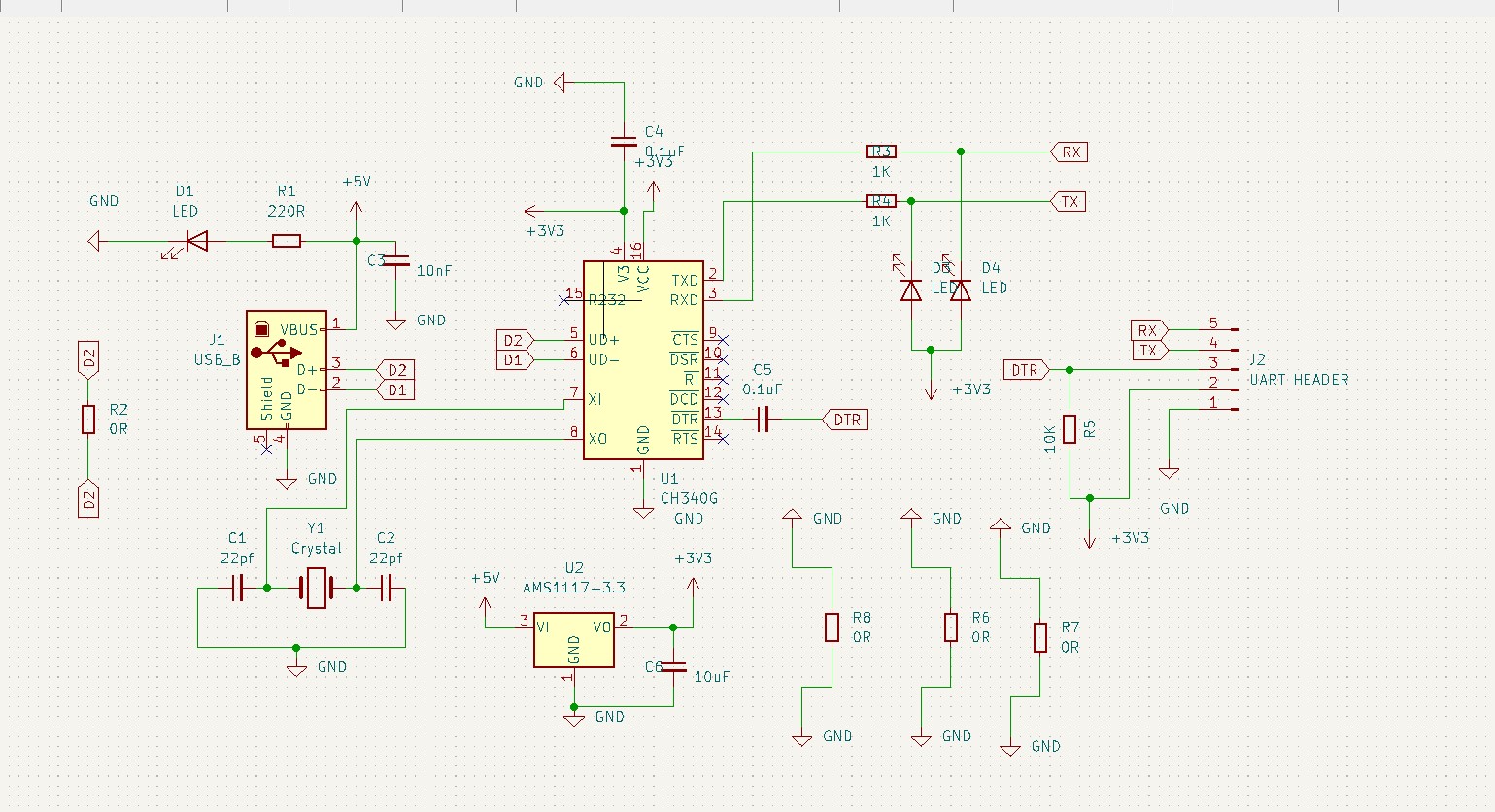
My first thing that come in my mind about this week Assignment is to make a UART avr programmer that i can use during programming my ESP-WROM-32 BOARD that i have to use during my final project . the reserach was not easy to find the trusted programmer circuit and i visited many links that giave me the idea to get started with . i visited this web and this one bout the information i got was somehow not accurate because those two links fous on the programmer targeting avr MCU's that use 5V as operating voltage but for me i have to target esp-wrom-32 which deals with 3.3V so i have to use a voltage regulator circuit that produces 3.3V output.finally this link helped me a lot coze i got an idea where to use a regulator and the good way of connecting ch34o usb to UART chip to be used while making the programmer.
The CH340G is a popular USB-to-serial converter chip that can be used to program ESP32 and ESP8266 microcontrollers. It is a low-cost and widely available solution for DIY programming boards.
One advantage of using the CH340G is its low cost, which makes it a popular choice for hobbyists and DIY electronics enthusiasts. It is also very easy to use, and can be interfaced with the ESP32 and ESP8266 microcontrollers using simple serial communication protocols.
Another advantage of the CH340G is that it is compatible with multiple operating systems, including Windows, Linux, and macOS. This makes it a versatile option for developers who work across different platforms.
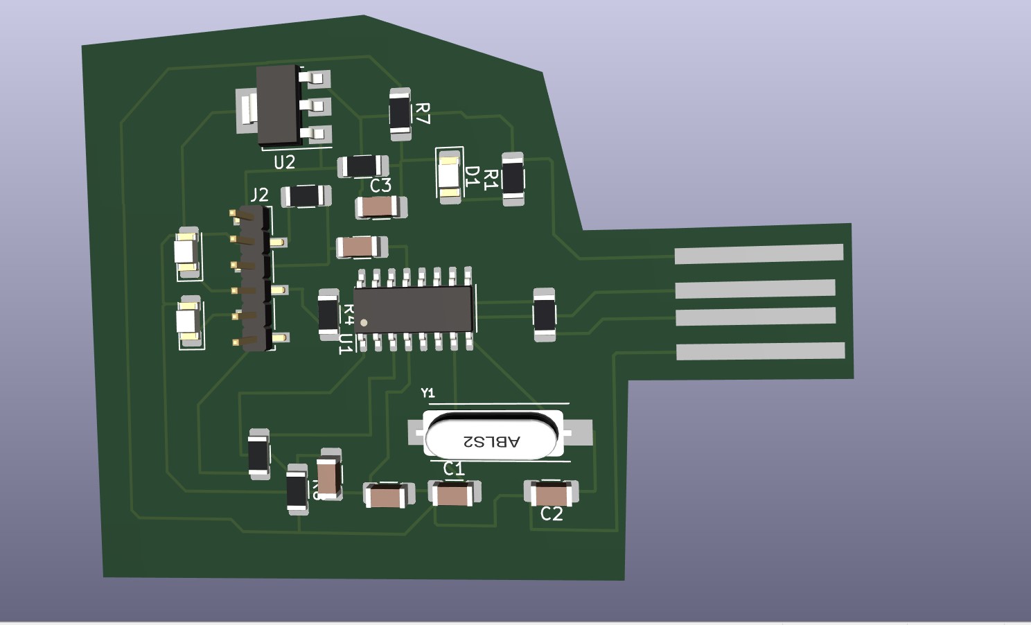
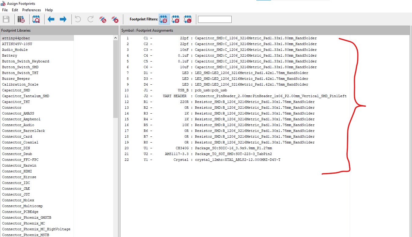
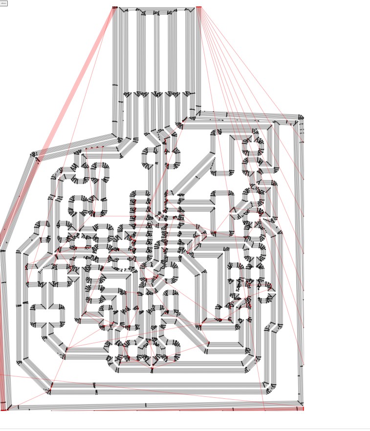
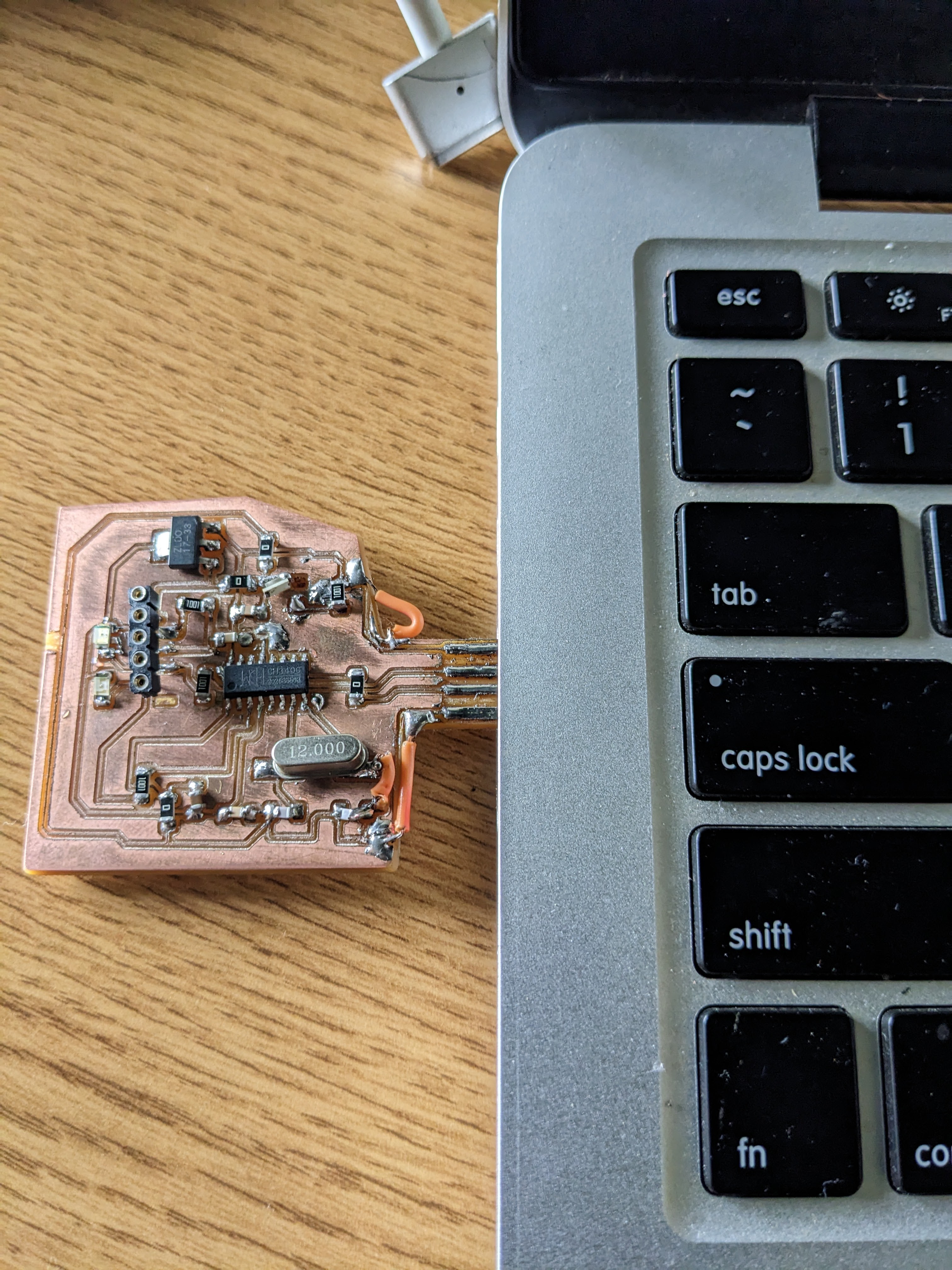
Making a circuit
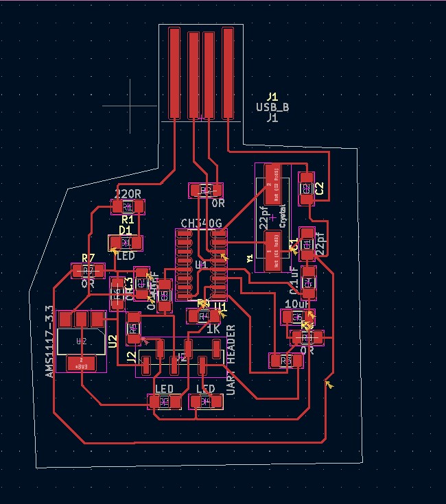
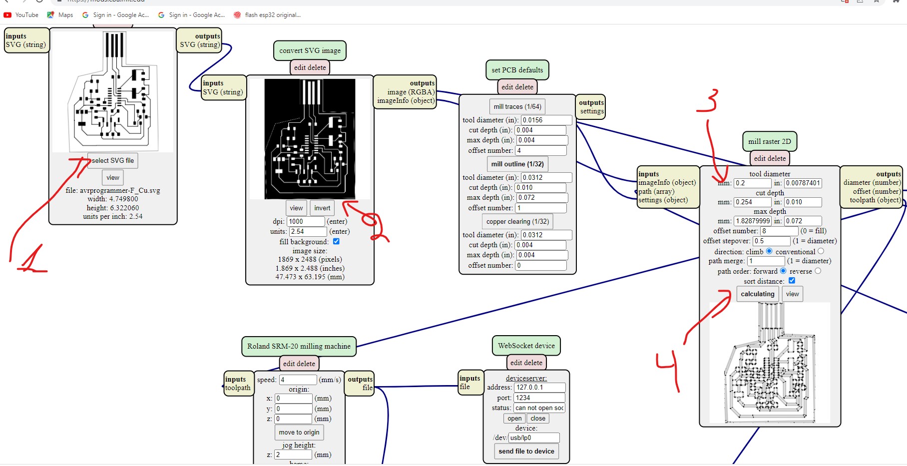
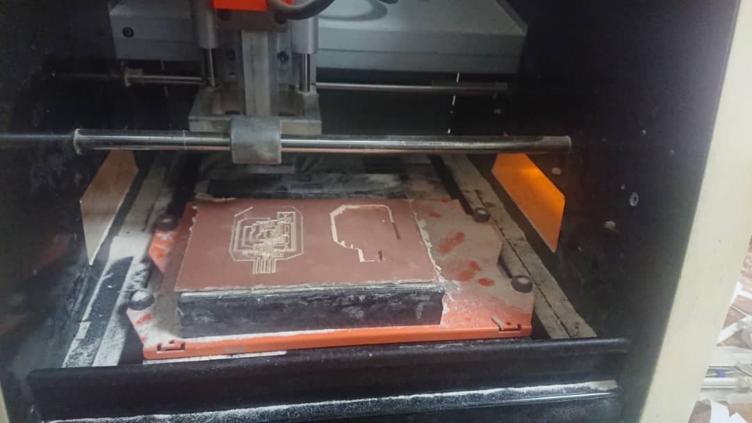
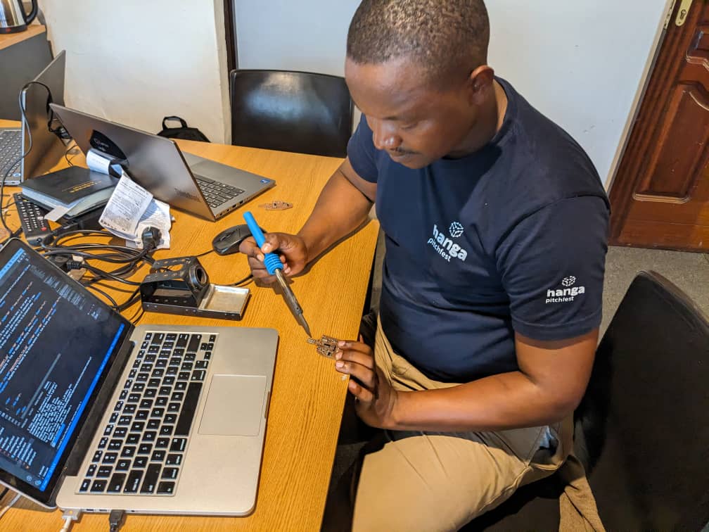
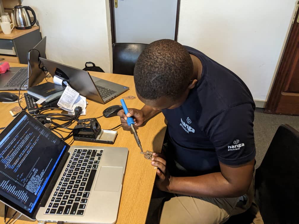
PCB Milling and Soldering components
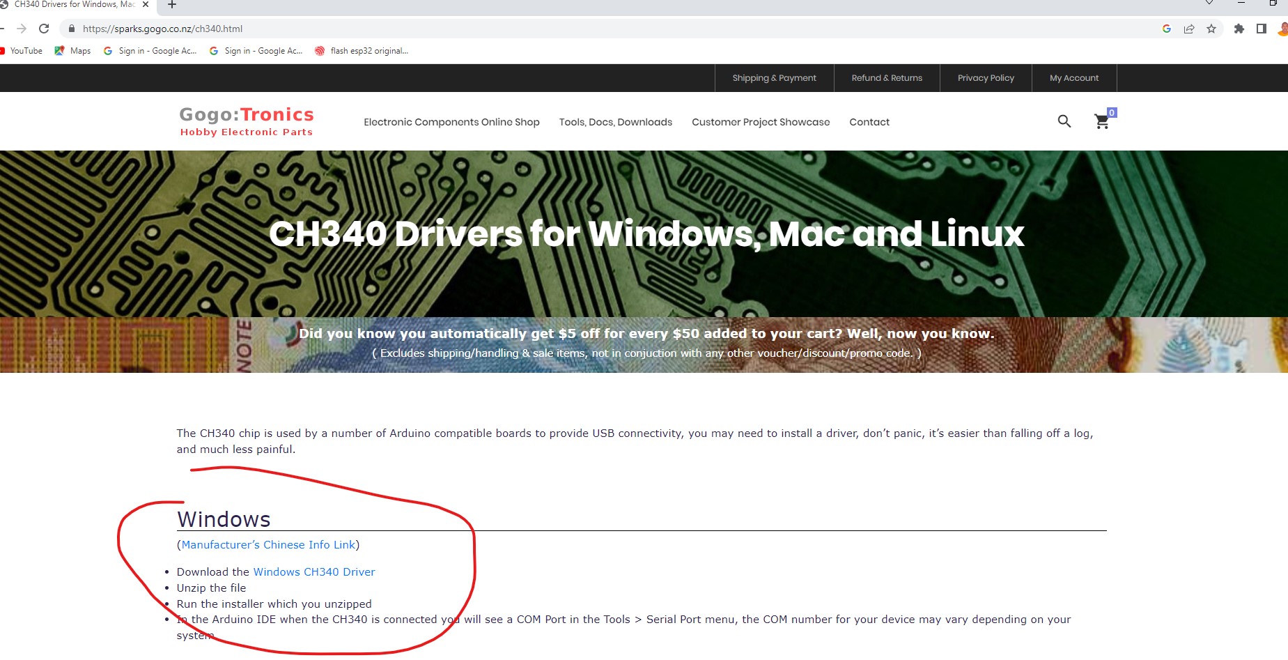
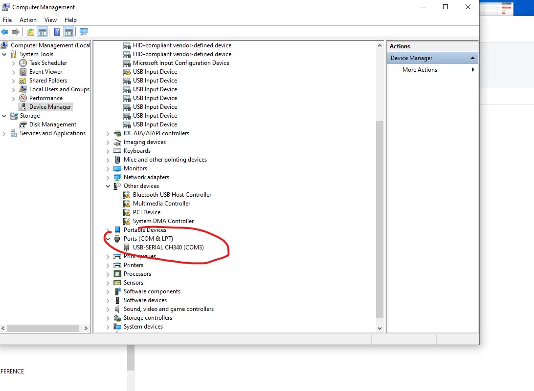
Installing ch340G driver in windows
this is the process of installing ch340g driver in windows
- Download the CH430G driver from the manufacturer's website or a reliable source.
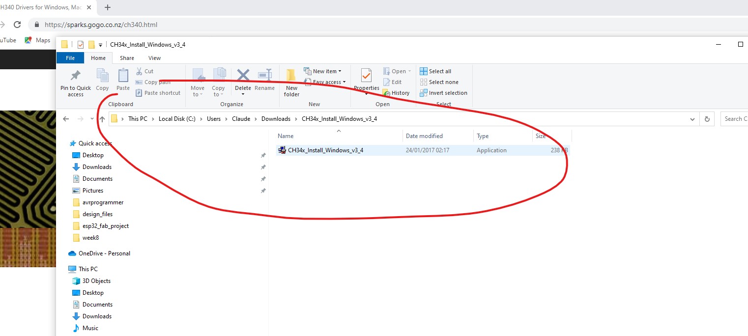
- Extract the downloaded zip file to a location on your computer.
- Connect your CH430G device to your computer via USB cable.
- Open the Device Manager on your computer. You can do this by right-clicking on the Start menu and selecting "Device Manager".
- Locate the CH430G device in the device list. It will likely be listed under "Ports (COM & LPT)" or "Other devices".
- Right-click on the CH430G device and select "Update Driver".
- Select "Browse my computer for driver software".
- Navigate to the location where you extracted the CH430G driver files.
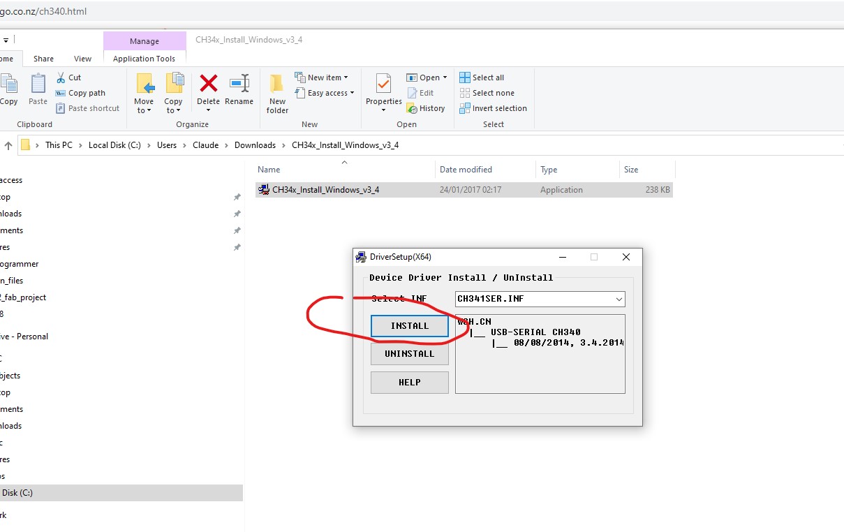
- Click "Next" to begin the installation process.
- Windows will install the CH430G driver and notify you when the process is complete.
- You can now use your CH430G device with your computer.
Testing the programmer on PC
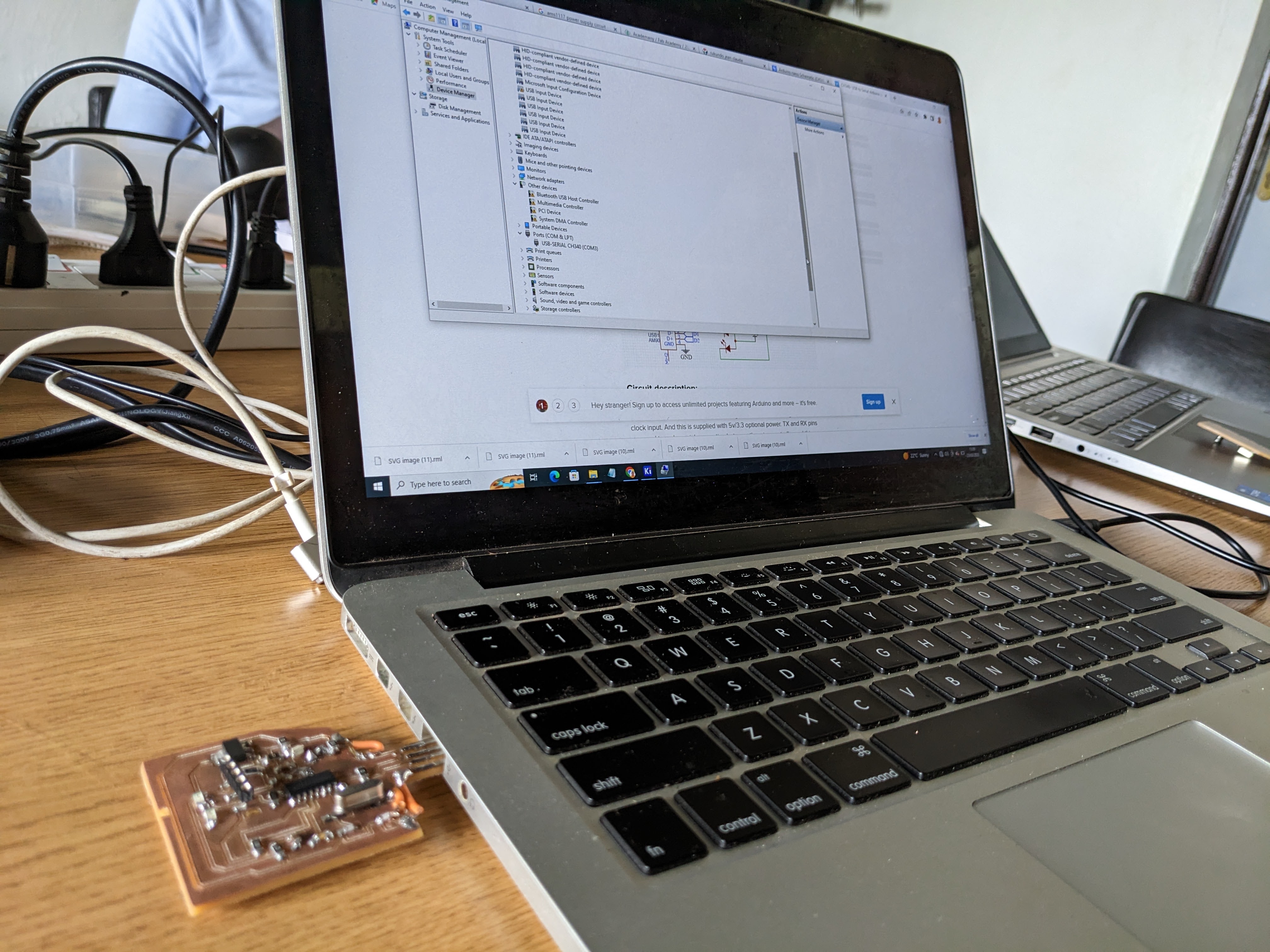
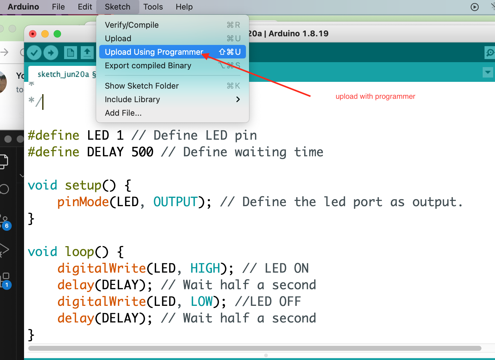
programming microcontroller with the produced programmer
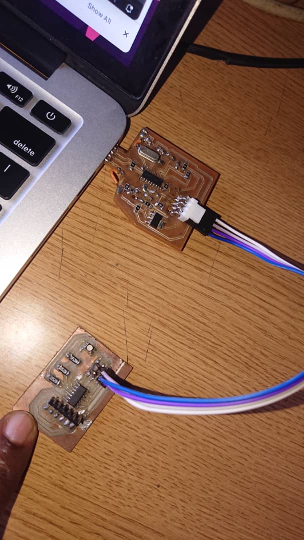
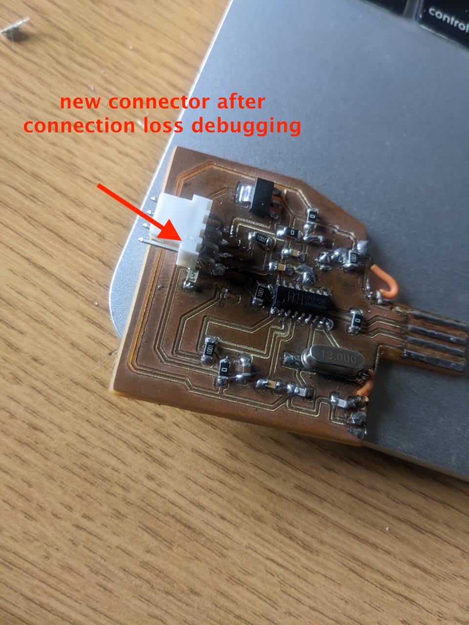
Even if the programmer is recognized by windows pc, the remaining is to uplaod code in the microcontroller to see if it works properly. so i tried my times with no luck but finally i realized the problem with the connector which was the soldering error. i replaced the connector.
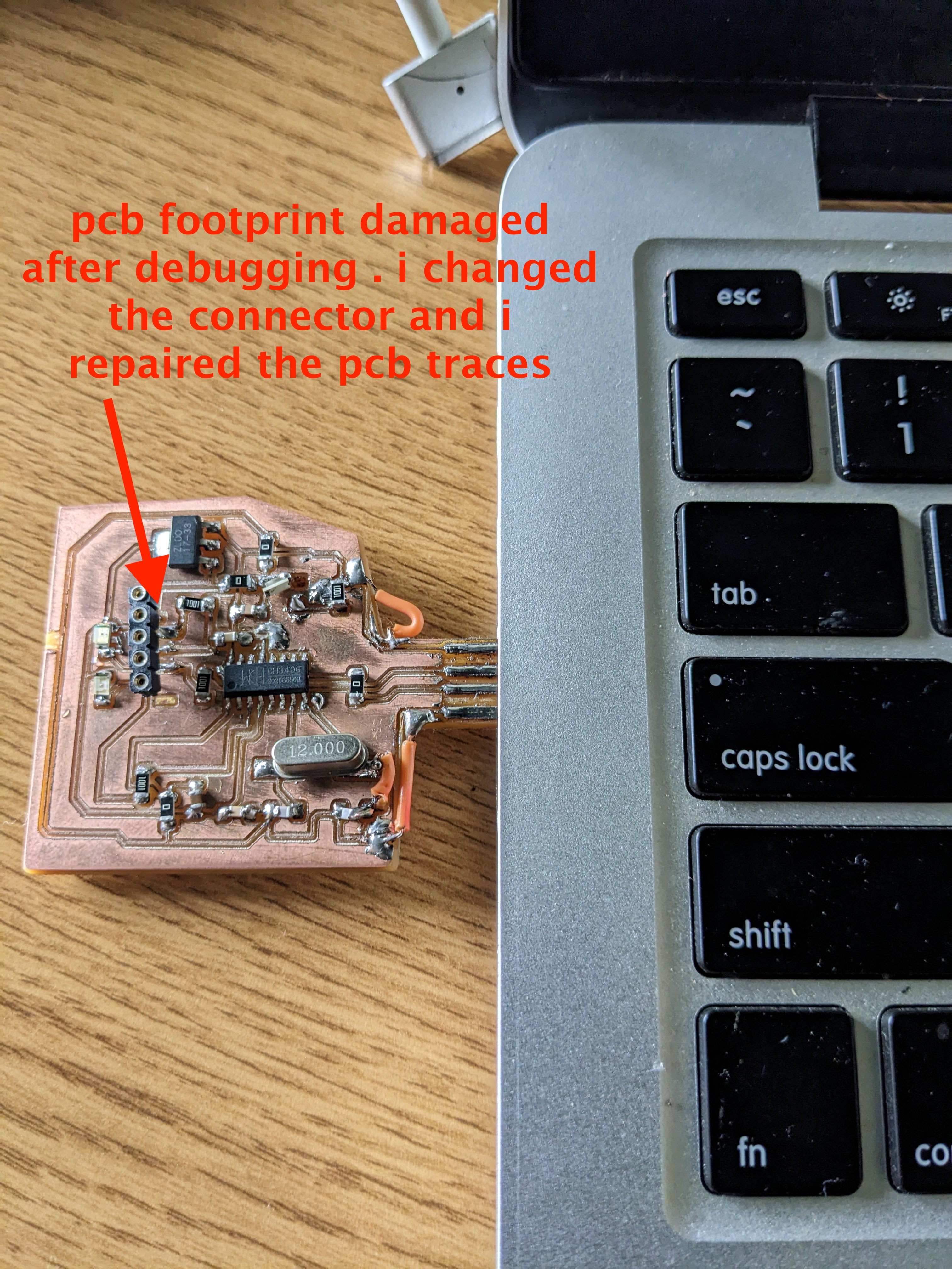
after noticing the issue, i corrected it and used new connector before trying code uplaod
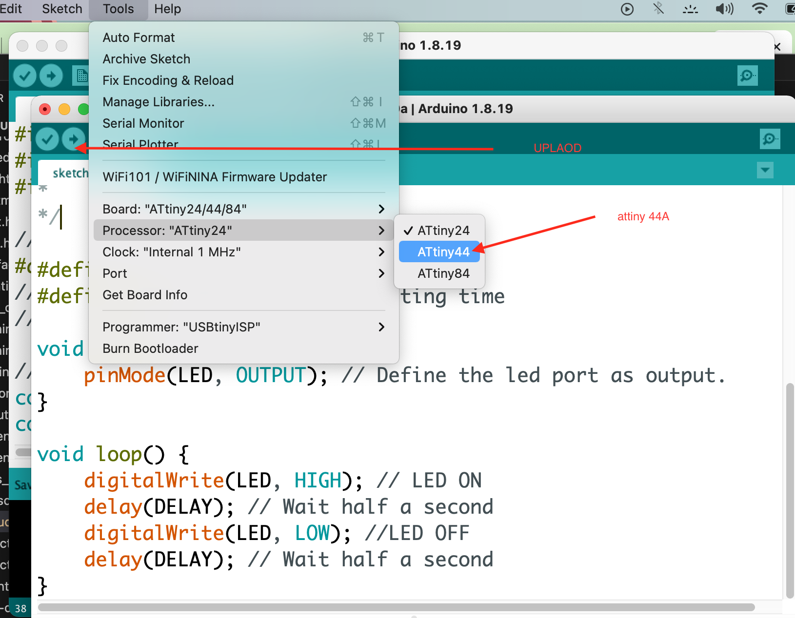
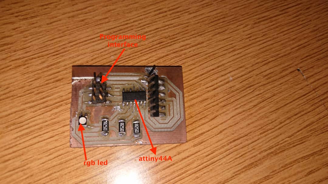
so i designed other board woth attiny44 and i programmed it with my programmer
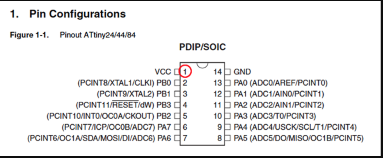
this is attiny44 chip. the circuit has RGB led to be used for testing successful code upload
code
                    /*
* Blink program
* An arduino program that blink the led
* connected to pin 1/PA5 of the MidTiny board (ATtiny1614).
*
* Author: Harley Lara
* Create: 03 May 2021
* License: (CC BY-SA 4.0) Attribution-ShareAlike 4.0 International
*
* This work may be reproduced, modified, distributed,
* performed, and displayed for any purpose, but must
* acknowledge this project. Copyright is retained and
* must be preserved. The work is provided as is; no
* warranty is provided, and users accept all liability.
*
*/

#define LED 1 // Define LED pin
#define DELAY 500 // Define waiting time

void setup() {
    pinMode(LED, OUTPUT); // Define the led port as output.
}

void loop() {
    digitalWrite(LED, HIGH); // LED ON
    delay(DELAY); // Wait half a second
    digitalWrite(LED, LOW); //LED OFF
    delay(DELAY); // Wait half a second
}