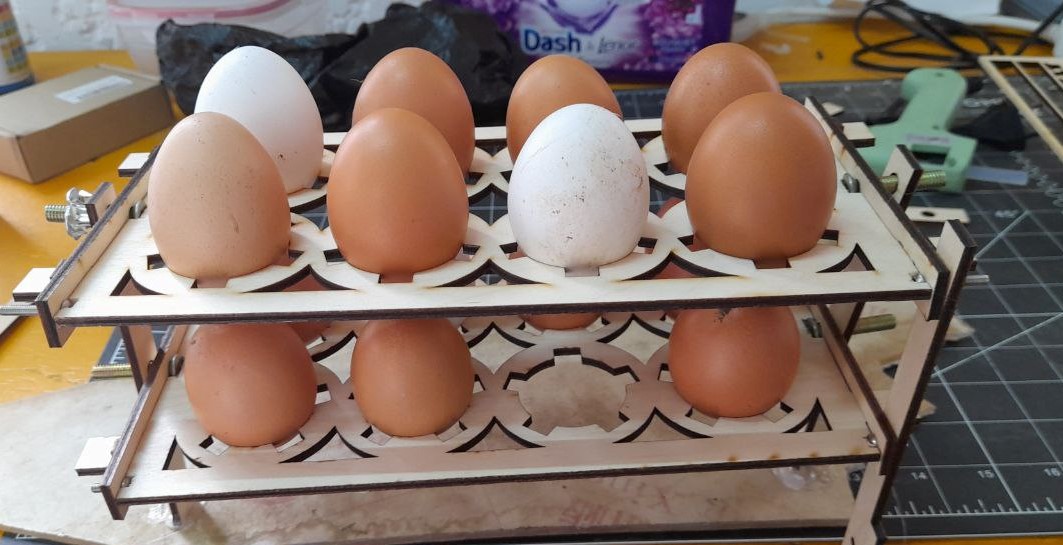
Hero SHot
Mechanism assembly
A video of the System
Computer controlled cutting Group assignment
together with our instructor, we did this week’s group assignment. This helped us characterize our materials cutting parameters and determine our machine Kerf Power speed for different Materials. we have also learned how to use our vinyl cutter.
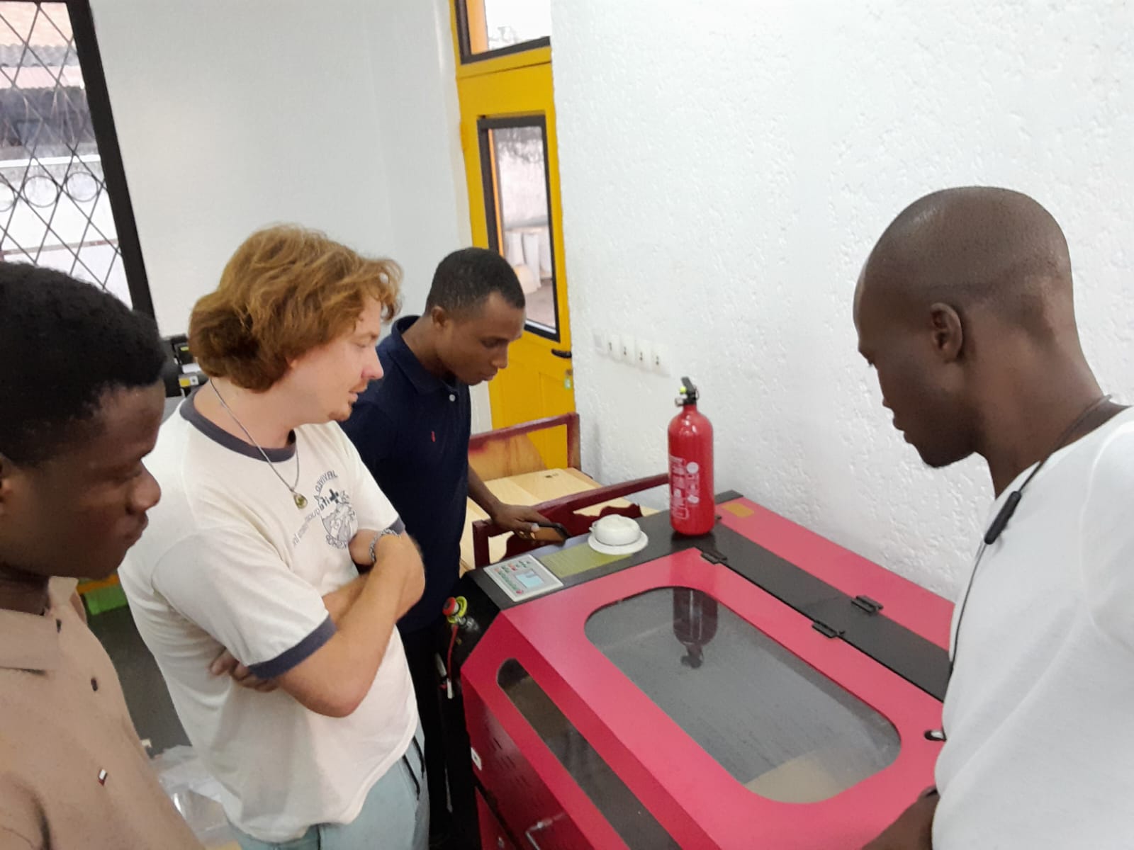
Laser Cutter
Our laser cutter at the EnergyLab is an OMTech 100W CO2 Laser Engraver Cutter. It has 20” x 28” working area. with a 100W CO2 Laser tube. It have a Ruida DSP Control System with a speed range 0-23.62 in/s and a cutting speed range 0-15.75 in/s
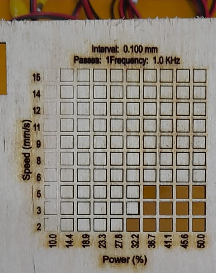
Speed and Power test
After the result in the picture bellow we know that this specific plywood can be cut trough with our laser power above 36.7% with a speed lower than 5mm/s
Card board joinery test
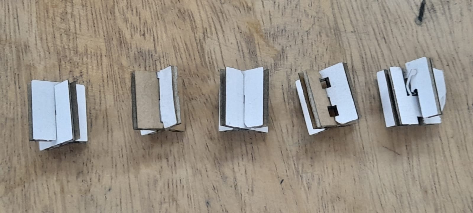
We did also a joinery test with card board A to evaluate different types of joinery techniques. We have tested various joints, such as finger joints, dovetail joints, or tab and slot joints, this allow us to assess their fit, strength, and aesthetics. This is useful to create intricate designs.
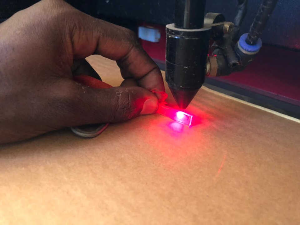
Laser cutter’s focus
To focus our laser we use the provided jig. After placing the material on the bed we use a knob to raise the bed putting the jig between the material on the laser nozzle. When the jig on the material surface is touching the nozzle (the distance) between the material and the head is equal to the Jig size it’s focused.
Our laser cutter’s kerf characterization
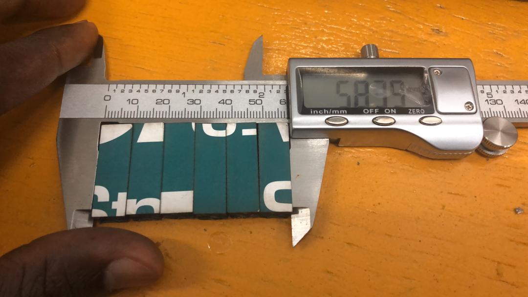
Laser kerf refers to the material that is removed as a result of the laser cut along the desired path. Taking out more material along that patch tha can be barely noticable but affect fitting of pieces. To measure it we design and cut six 10 mm strips making 7 laser cuts that we place them next to each other and measure the total length. The kerf is then calculated as (planned length - measured length) / number of cuts
in our case it’s 0.23 ei (60mm-58.39)/7
Accounting for the laser cutter kerf in design parts
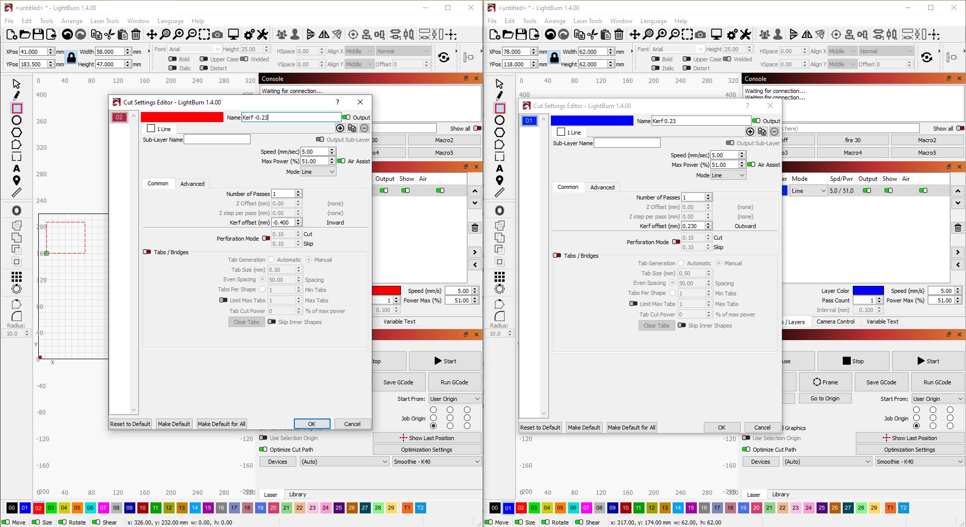
in our design we can adjust Dimensions to compensate for the 0.23mm kerf, subtract that amount from the desired dimensions of our design. For example, if we want a part of 50mm final width, we design it with a width of 49.77mm (50mm - 0.23mm). If we have parts that need to fit or interlock with each other, we can increase the width of slots or decrease the width of tabs by 0.23mm to ensure a proper fit after laser cutting.
In Lightburn we can do that in the software while setting the layer speed and cut parameters.
Vinyl Cutter
Parametric 2D modelling
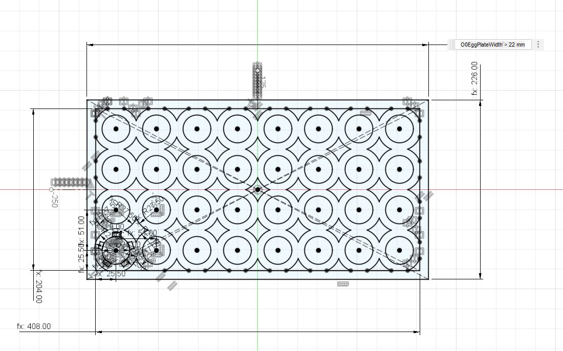
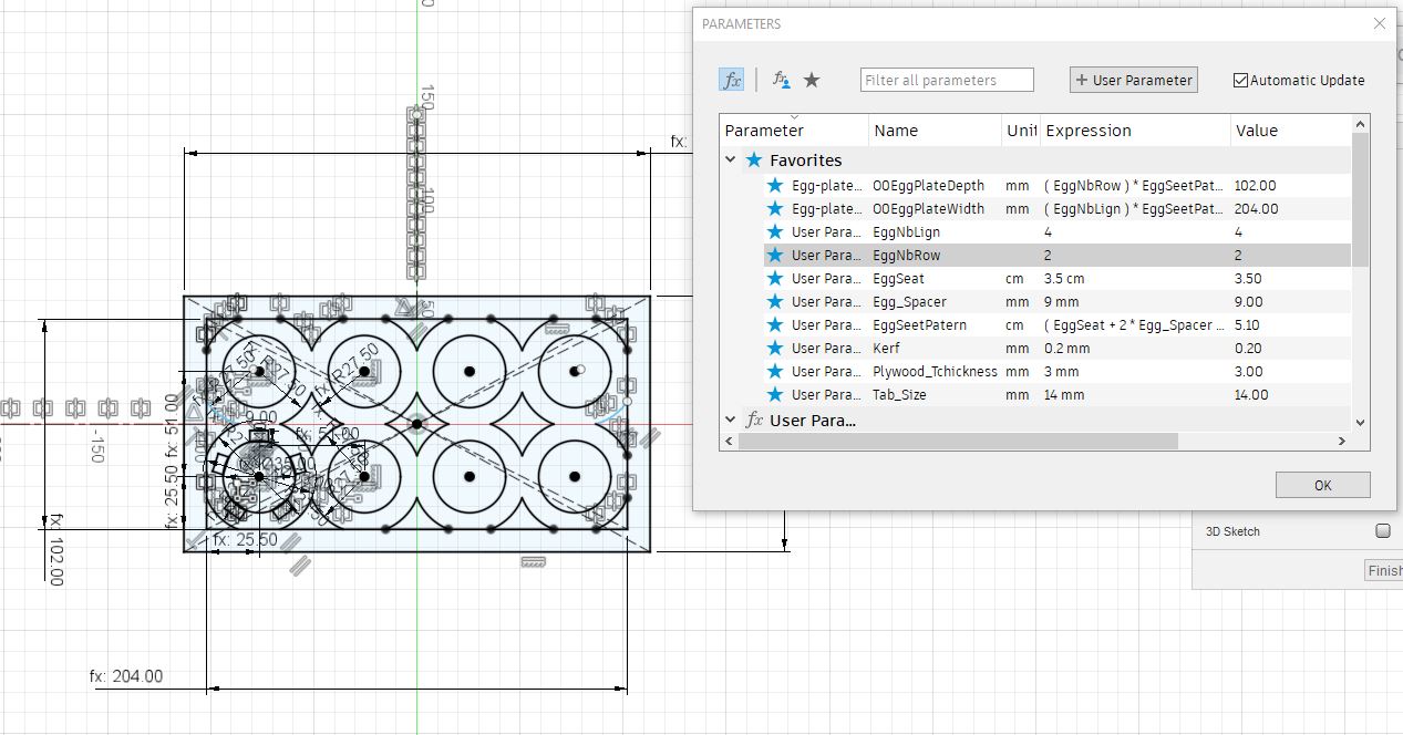
I have continued the design of my egg rack adding more parameters to make a 2D laser cutter set to test my design and mechanism. I have made it so that when I input the egg capacity for on tray it adjusts its size automatically. So just inputting the Number of rows and the number of line on the rack the geometry is resized.
Using the laser cutter
Process :
From a 2D design, we have to import a DXF to the laser software to send the job to the machine. For our laser cutter, I used Lightburn before sending the job to the machine we need: * to add and configure our machine is not already done. * Import the .DXF file and position it on the working area and origin; making sure it’s not oversized. * We set the cutting frequency, speed and power according to our material Now we can turn the machine on and send the job to it. NB: if the machine is on we can check the job size and the cutting area with the frame command. With the laser off, It will follow the job outline so we make sure our material has the minimum needed size and is well positioned.
The first thing on using the laser cutter is :
- Safety google, fume exhaust not leaving a print unattended
- position the piece
- Adjust the focus hight
- Set the origin
- Turn Air-assist and Exhaust extractor ON
- Send the job from our computer with the cutting parameters (Speed and laser power).
More on Lightburn software
Lightburn is a software package that allows you to prepare your projects for laser engraving and cutting. You can create projects from scratch or import them in various file formats like AI, DXF, PNG, JPG, BMP, and SVG. The software is compatible with Windows, macOS, and Linux operating systems. I’ts not a freeware and alow interfacing with various Firmware and hardware (GRBL controller, DSP Controllers…)
More : * How to Use Lightburn for Laser Engraving and Cutting * and here Getting Started With LightBurn: Set up & First Project
Our laser cutter have a DSP controller so I had to upgrade my License
What I did with the Laser cutter
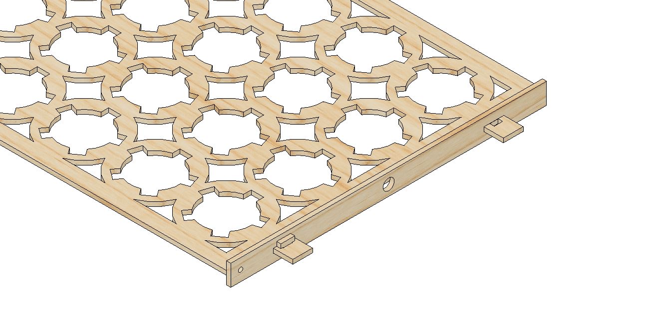
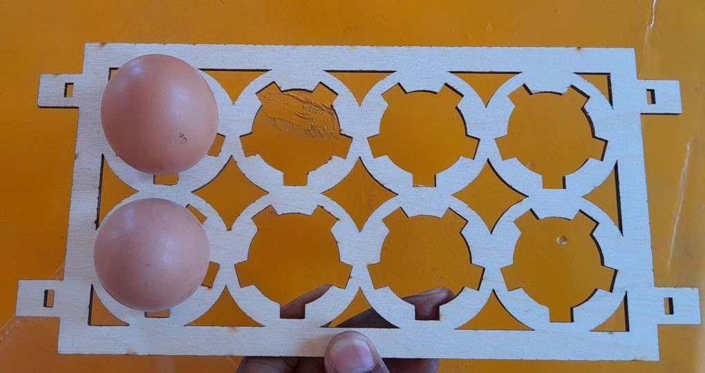
I then proceeded with a more complex parametric tray system. Similar to what I need in my project. I have chosen the wedges joint method as a need my joint to be tight.
Starting from the egg tray plate
I have added the wedge joint design linked to our laser cutter kerf and my material thickness. I have also used the rack size to automatically position the other features like axis hole as a need something that can change position and have a rotation center.
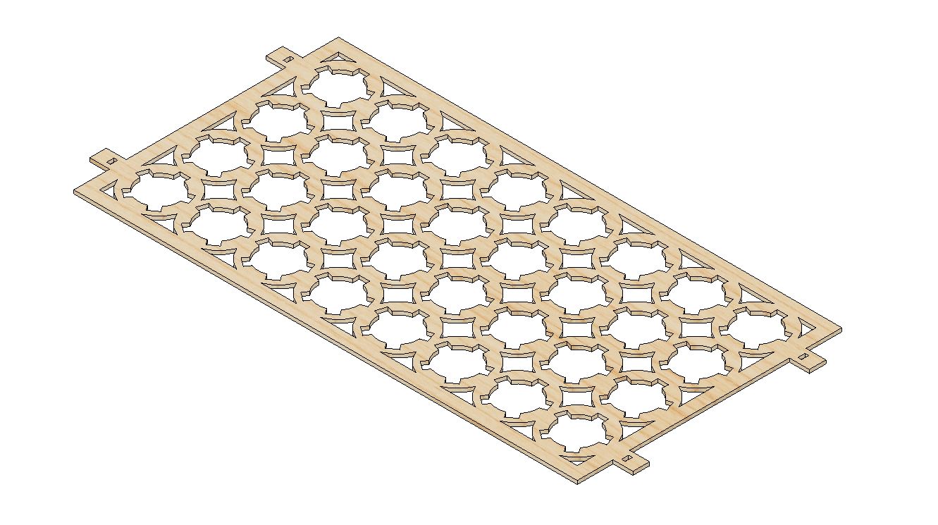
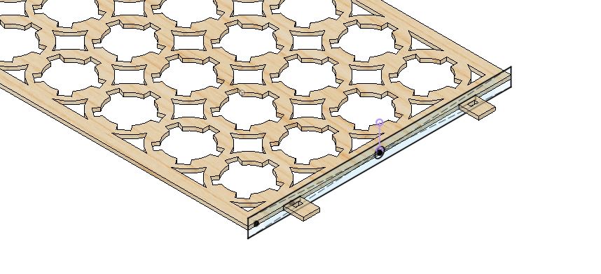
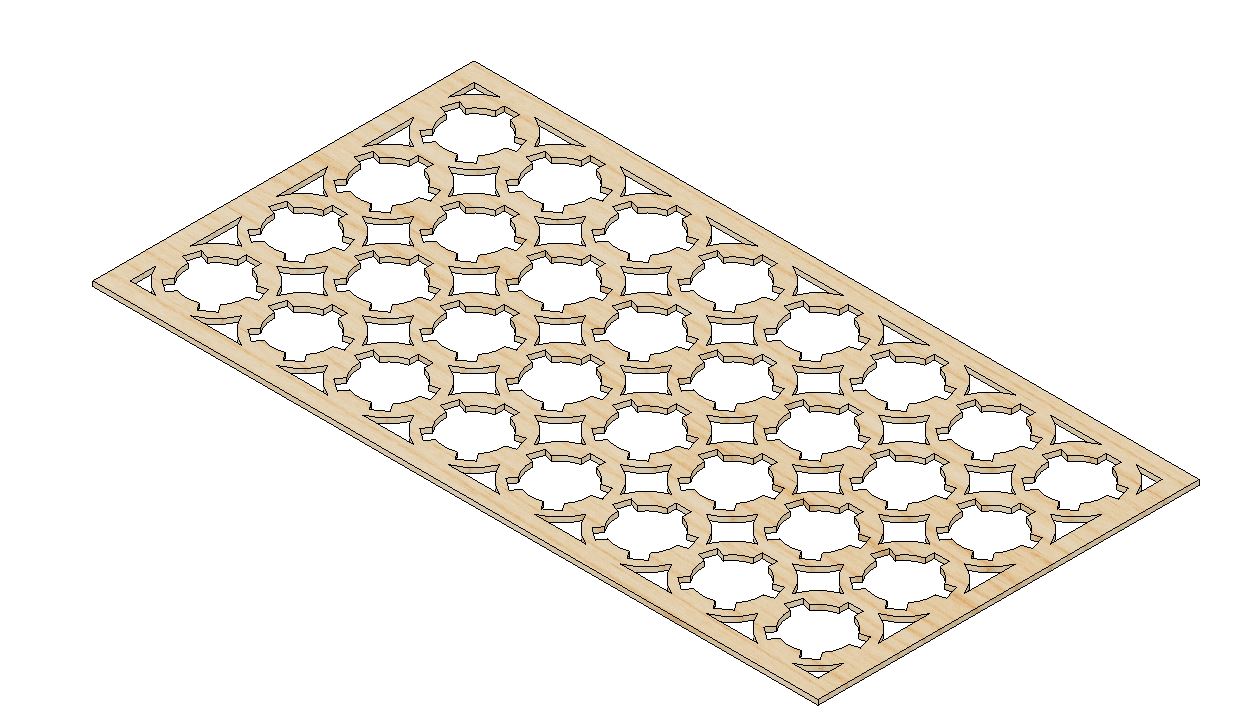
That lead me to the design below without 3d printed parts even if my mechanism will later have 3D printed parts.
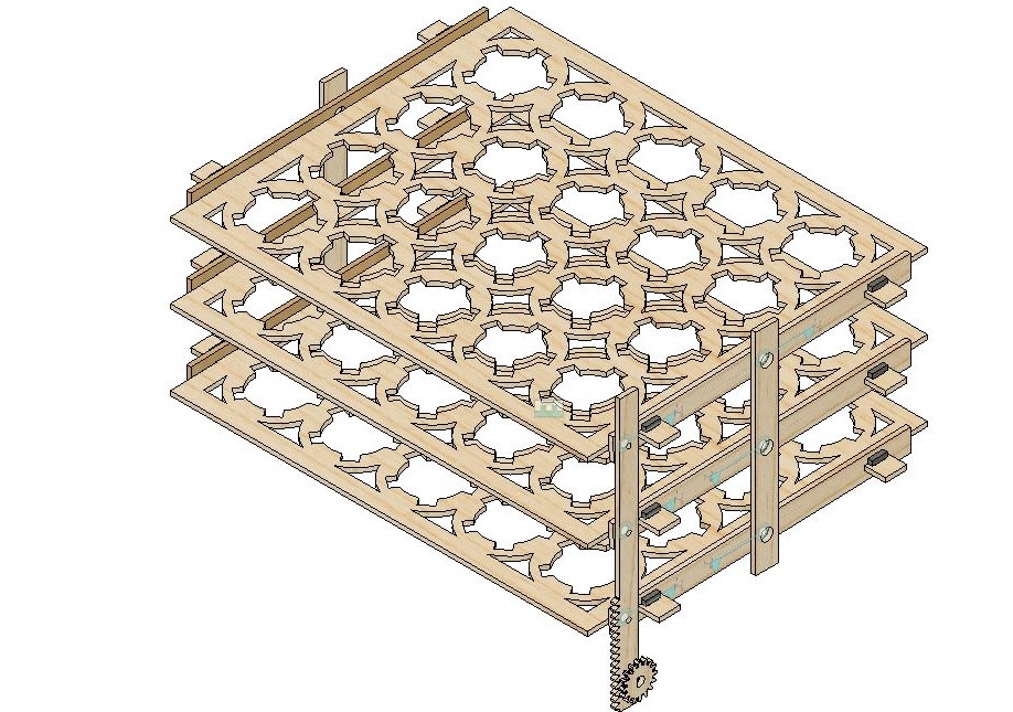
with this design, I Have added joints to test my mechanism I Have then discovered an issue to solve later :
Vinyl Cutting with the SINOVINYL 1351LA
More about the Machine :
| Designation | Value |
|---|---|
| Type | SINO-1351 |
| Media way | Floor stands |
| Max paper feed width | 1350mm |
| Max cutting width | 1260mm |
| Max cutting speed | 800mm/s |
| Max cutting length | 20000mm<=20 |
| Max cutting thickness | 1mm |
| Main board | 16-bit CPU, 1MB-4M High-speed CACHE memory |
| Control panel | over-head, 2*8LCD, 13-button touch thin-film keyboard |
| Driver | High stepping motor, micro-step driver |
| Knife press | 0-500g( digital adjustment) |
| Mechanical resolution | 0.05mm |
| Repeatability | <+-0.1mm |
| Type of tool | carbide blade |
| Plotting pen type | all types diameter 11.4mm plotter pen |
| Plotting instruction | DMPL, HPGL automatic identification |
| Interface | COM, USB & LPT (optional) |
| Power supply Switching power supply, | AC110/220V±10% 50HZ |
| Power consumption | <100VA <120VA |
| Operating environment Temperature: | +5oC to +35oC, relative temperature 30%-70% |
| Operating | language English |
| Operation system | Windows XP, Windows Vista, Windows7(32bit & 64bit), Windows8 |
| Applicable software | Flexistarter10.5 / Signmaster Cut / Coreldraw / Artcut |
How to operate the Vinyl cutter / Work Flow :
-
We use InkScape for the designing or importing bitmaps and converting to vectors (output SVG File)
-
First we load the material placing the vinyl roll on the cutter’s material holder. We align it with the front and back guidelines. Adjust the material holder’s width to fit the vinyl roll ad engage then to lock it in place and set the origin on our job on the material.
-
We now connect the Vinyl Cutter to our computer using an USB or serial cable and power the machine.
-
We start the SignMaster software and select the Cutter.
-
we configure the cutting parameters according to your requirements. Specify the vinyl width and length, cutting speed, cutting force, and any other settings based on the material you are using.
-
we Import our design file (typically in .svg, .dxf, .ai, or other compatible formats), adjust the design’s size and position to fit within the vinyl material.
-
Once your design is ready, Send it to the Cutter. While the cutter is cutting our design Keep an eye on the cutting process to address any issues that arise promptly (to deep cuts…).
-
Once the vinyl cutter has completed the cutting process, we cut the roll to the job size take it out and do the weeding (remove the excess vinyl material carefully) leaving only your desired design on the backing sheet.
-
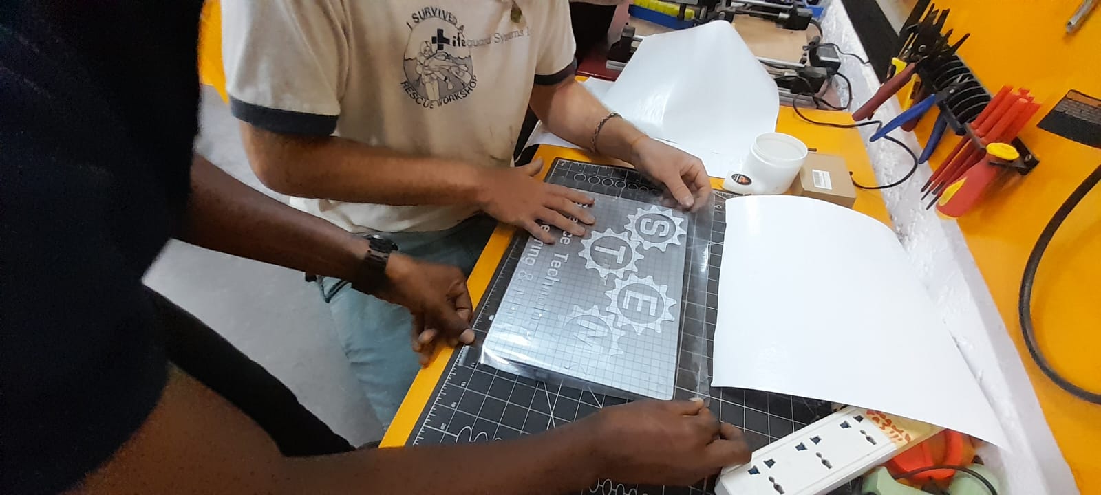
We then use an application tape or transfer tape to lift the vinyl design from the backing sheet and apply it accurately to the desired surface ta we have to make sure is clean(not dusty or oily).
What I did with it :
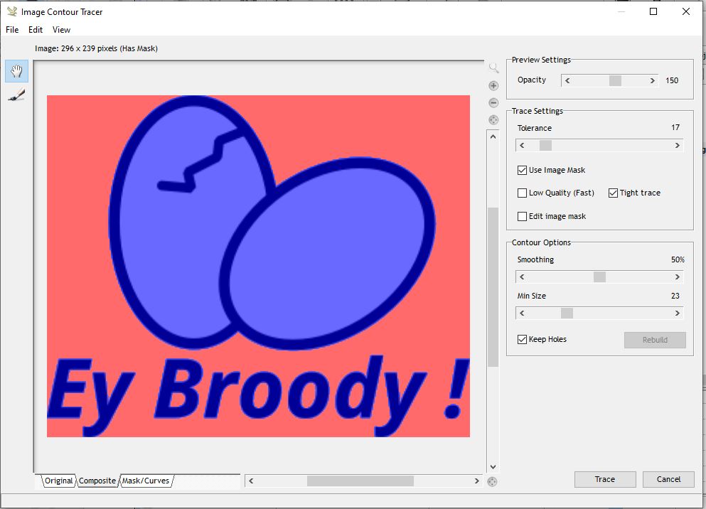
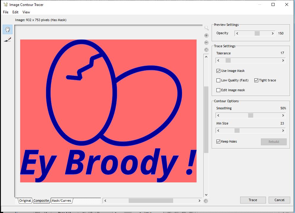
For the vinyl cutting, I choose to Make a logo Sticker to brand my Project. I choose the previous logo design on week 02 and added a contour to it.
to do that I had to make my white infill in the design transparent as it is a different color if I want to cut it will have to do it separately. I have used sign master as software.
Hero shots of this week’s results
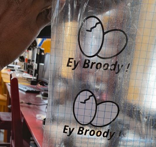
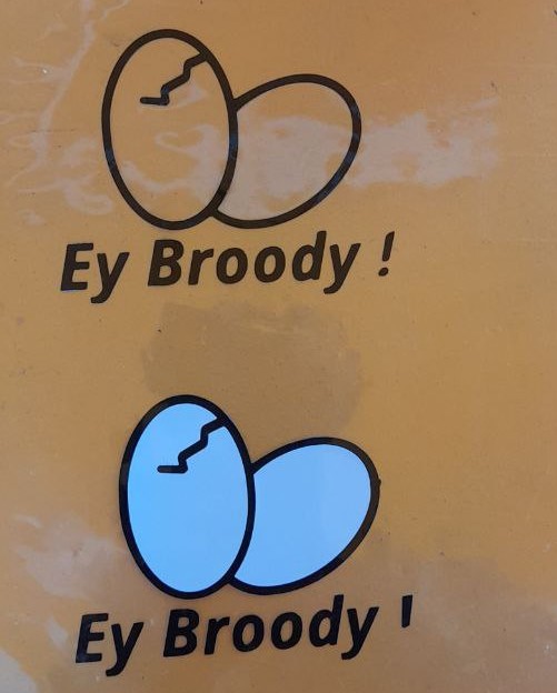
Pictures of vinyl Cut
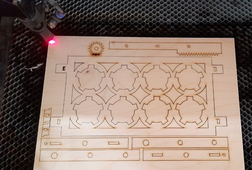
Pictures of laser cut
Mechanism assembly result for test:
A video of the System