Electronics production
Group Assignment
Individual Assignment
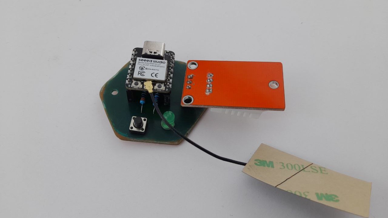
hero shot
Electronic Design
For This week assignment I have Use my previous design on ‘Week 06 - Electronics design’ and have designed a PCB Heater Board.
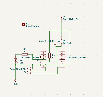
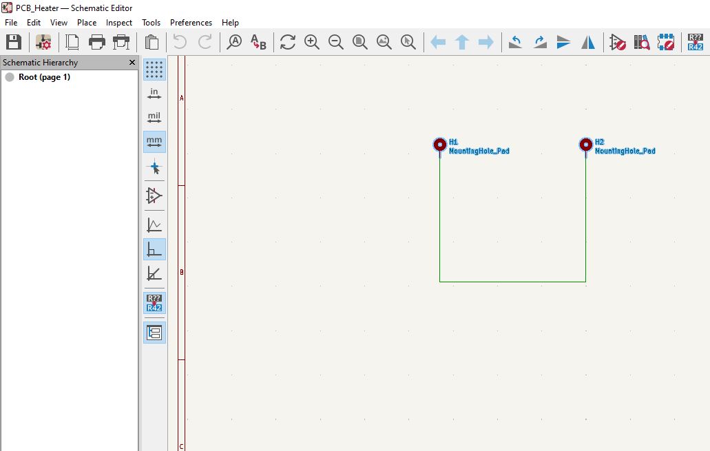
Schematic
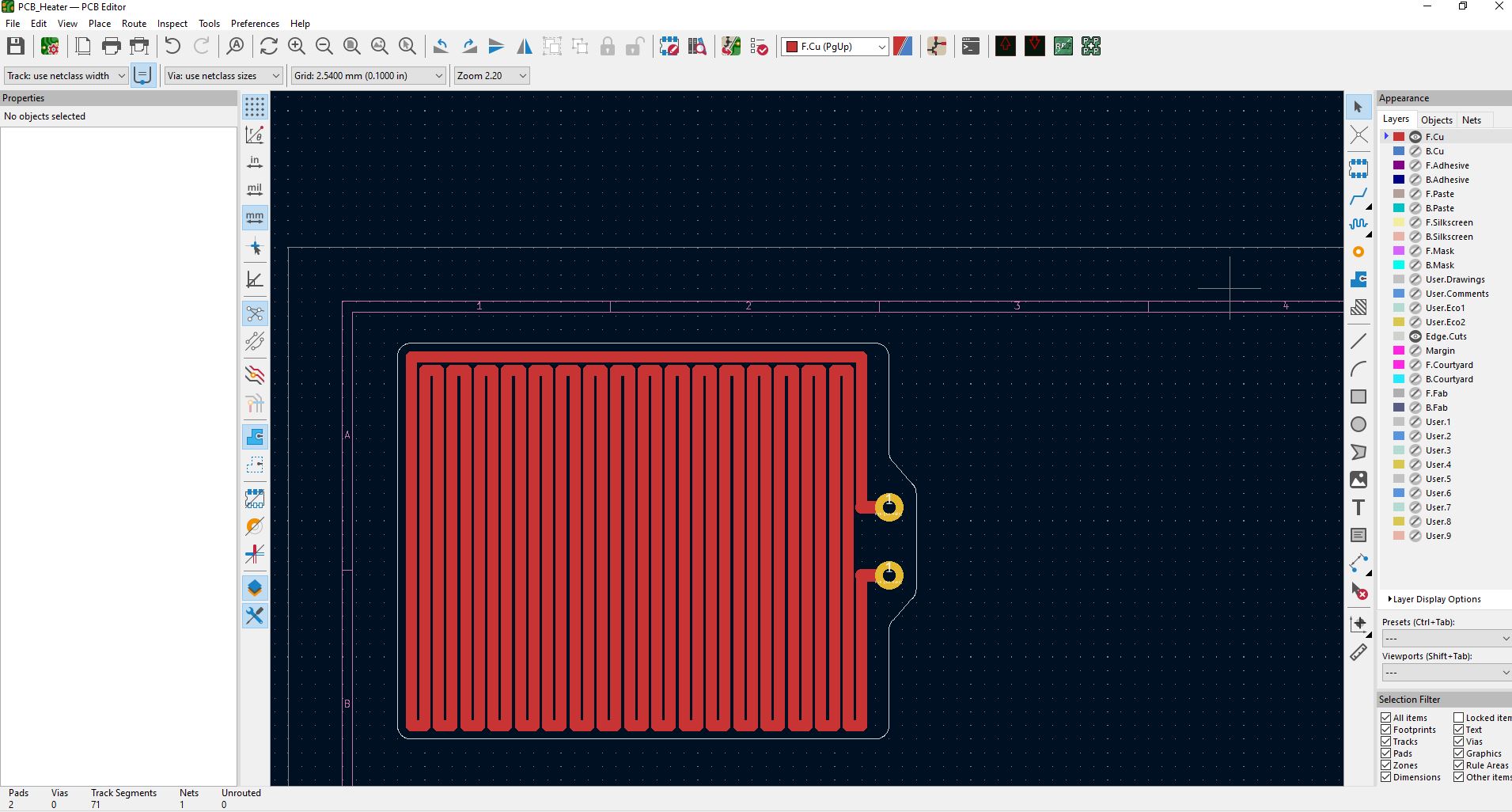
PCB
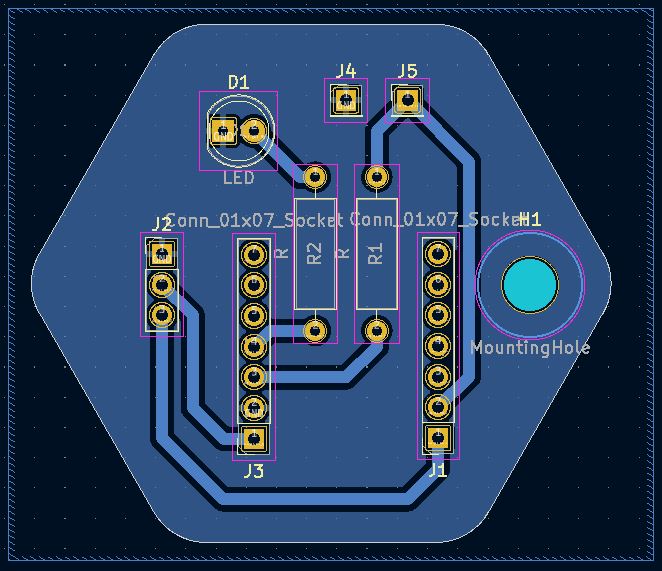
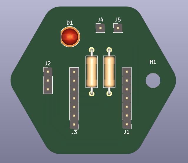
PCB render
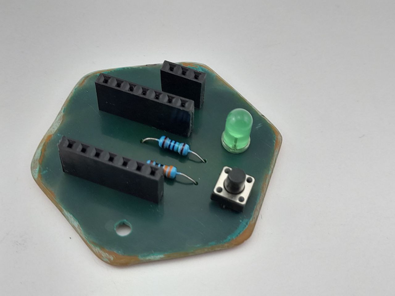
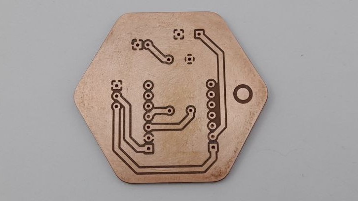
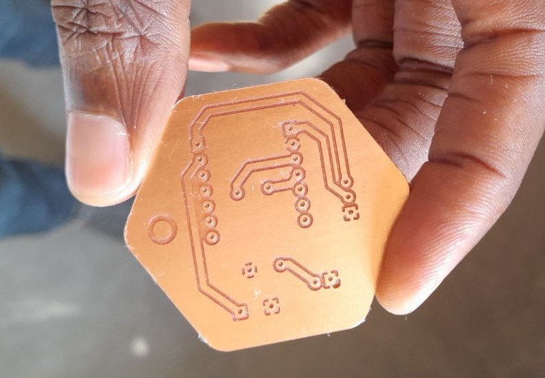
Picture of the result
WorkFlow
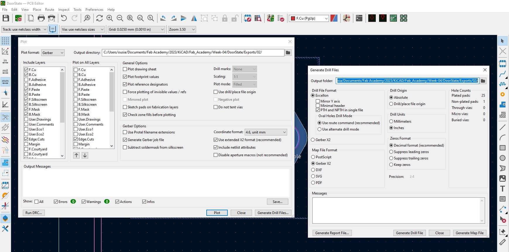
From KiCad I export the Gerber of y files and Drill Files.
Using Flatcan I generate the geometry of the object (either the Copper layer, The edge cut or the Drill file). From the generated Object I then generate the CNC Job and send it the CNC for Milling.
Workflow from KiCad to FlatCAM for generating CNC code for PCB milling:
-
To generate the CNC code for PCB milling from KiCad, I used a third-party tool called Flatcan. Here’s how I did the process:
-
Design of the printed circuit in KiCad: I used KiCad to create my electrical diagram and my PCB. I drew the tracks, pads, vias and copper zones according to my needs. Once the design was complete, I checked the component routing and alignment.
-
Exporting Gerber files: Once the design was complete, I used KiCad to export the necessary Gerber files. Gerber files contain the design information needed to fabricate the PCB, including copper layers, Edge cuts, and Drill file.
-
Importing Gerber files into FlatCAM: I opened FlatCAM and imported the previously exported Gerber files and Drill Files. FlatCAM has the ability to read and interpret Gerber files to generate a visual representation of the PCB.
-
Machining parameters configuration: In FlatCAM, I configured the machining parameters such as cutter thickness, rotational speed, milling depth, etc. These parameters depend on the material of the printed circuit board and the cutter being used.
-
Generation of the machining code: Once the machining parameters were configured, I asked FlatCAM to generate the corresponding CNC code. FlatCAM analyzed the PCB design and generated G-Code, which is a programming language used by CNC machines to control the movement of the cutter.
-
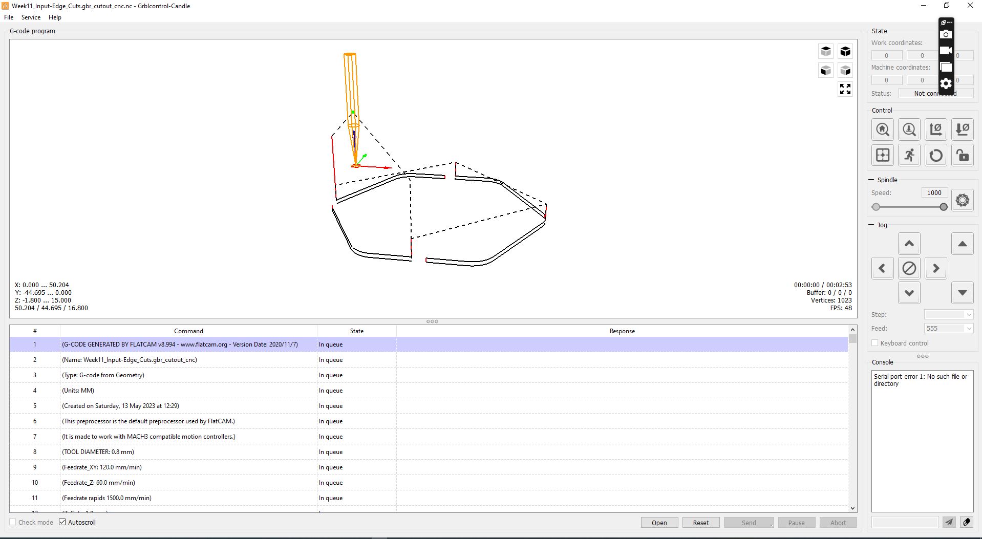
Transferring the machining code to the CNC machine: Once the CNC code was verified, I transferred it to the CNC machine I was using for milling the PCB. I used CNC control software Candle to load the CNC code and initialize the machine.
-
Starting the machining: After loading the CNC code into the CNC machine, I started the machining process. The machine followed the CNC code instructions to move
Stuffing the Board and soldering components
for SMD Components I have Used MINIWARE MHP30 Electric Hot Plate .
After applying the solder paste I placed the components using a twizer waited from the Hot pate to heat the set Temperature of 210° C.
Then I have placed the PCB on The plate adjusting it so most of the component and paste receive the heat, waited for the paste to melt and hold the components to the cooper. I then gently took the PCB from the plate and let it cool down.
I have also used trough hole because of easy and local availability. To solder them I used a soldering iron and solder.
Trying SolderMask Application
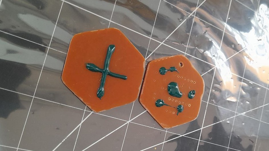
I have tried Solder Mask Application on my board Using UV solder mask; a FEP sheet; and an UV light.
Applying Solder mask
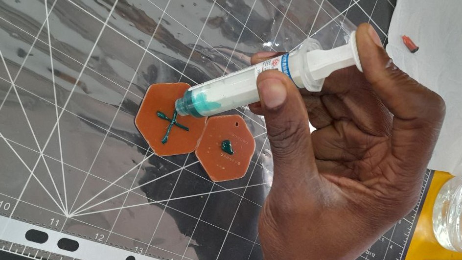
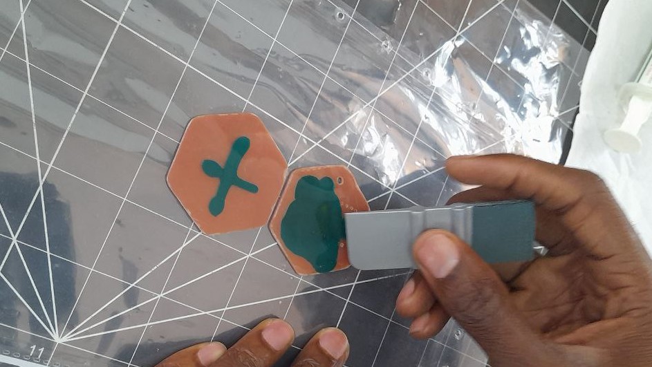
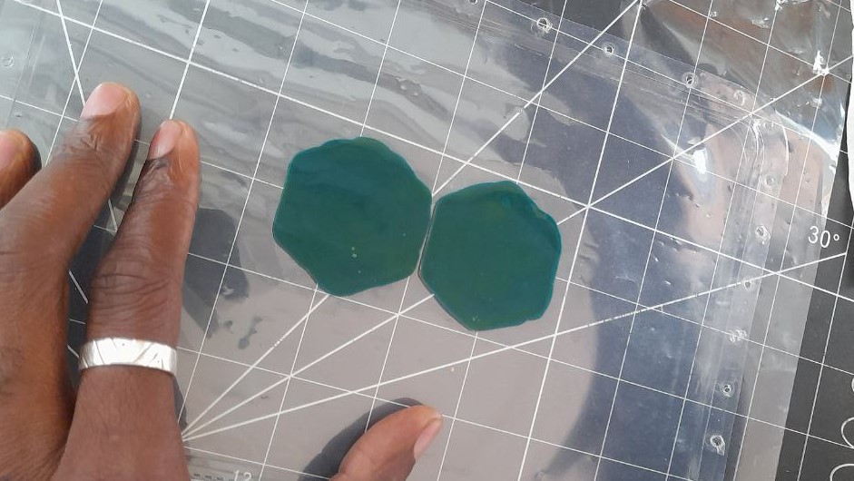
Spreading the UV Mask with the FEP sheet on top.
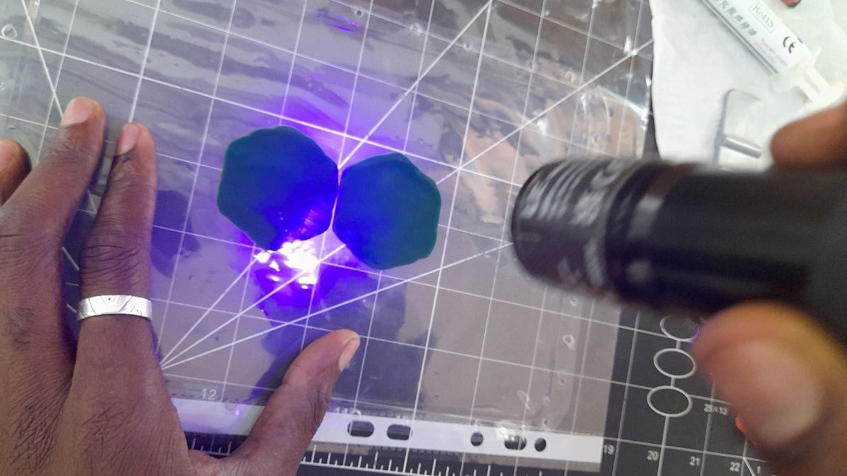
Curing Uv Mask
Trying a Joule PCB heater
For my project I need a Heating element. Here I have tried to design one ( a PCB Heater) with KiCad.
Design in KiCad
Schematics
Pcb design with 2.0 mm traces
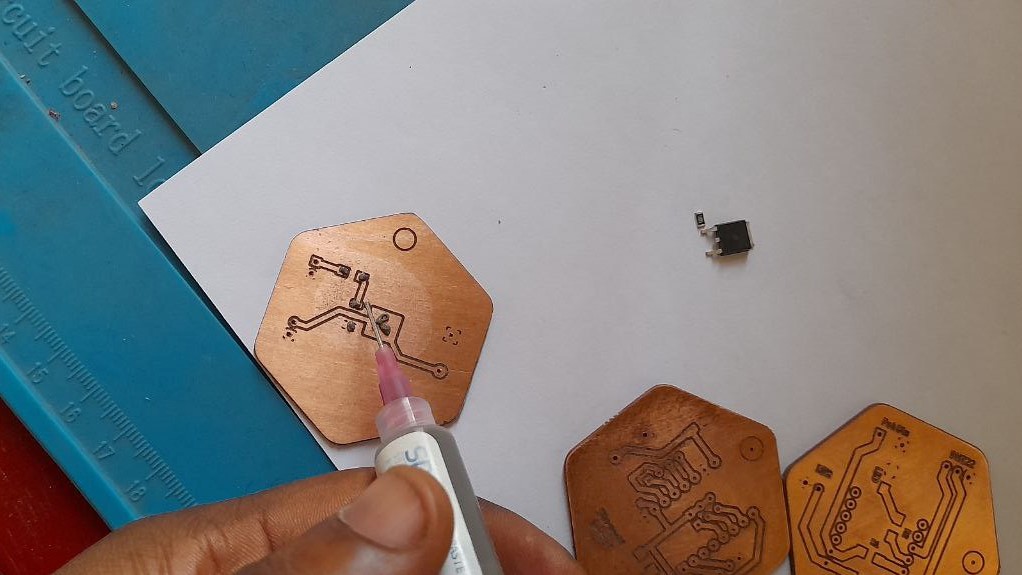
Milling Prep
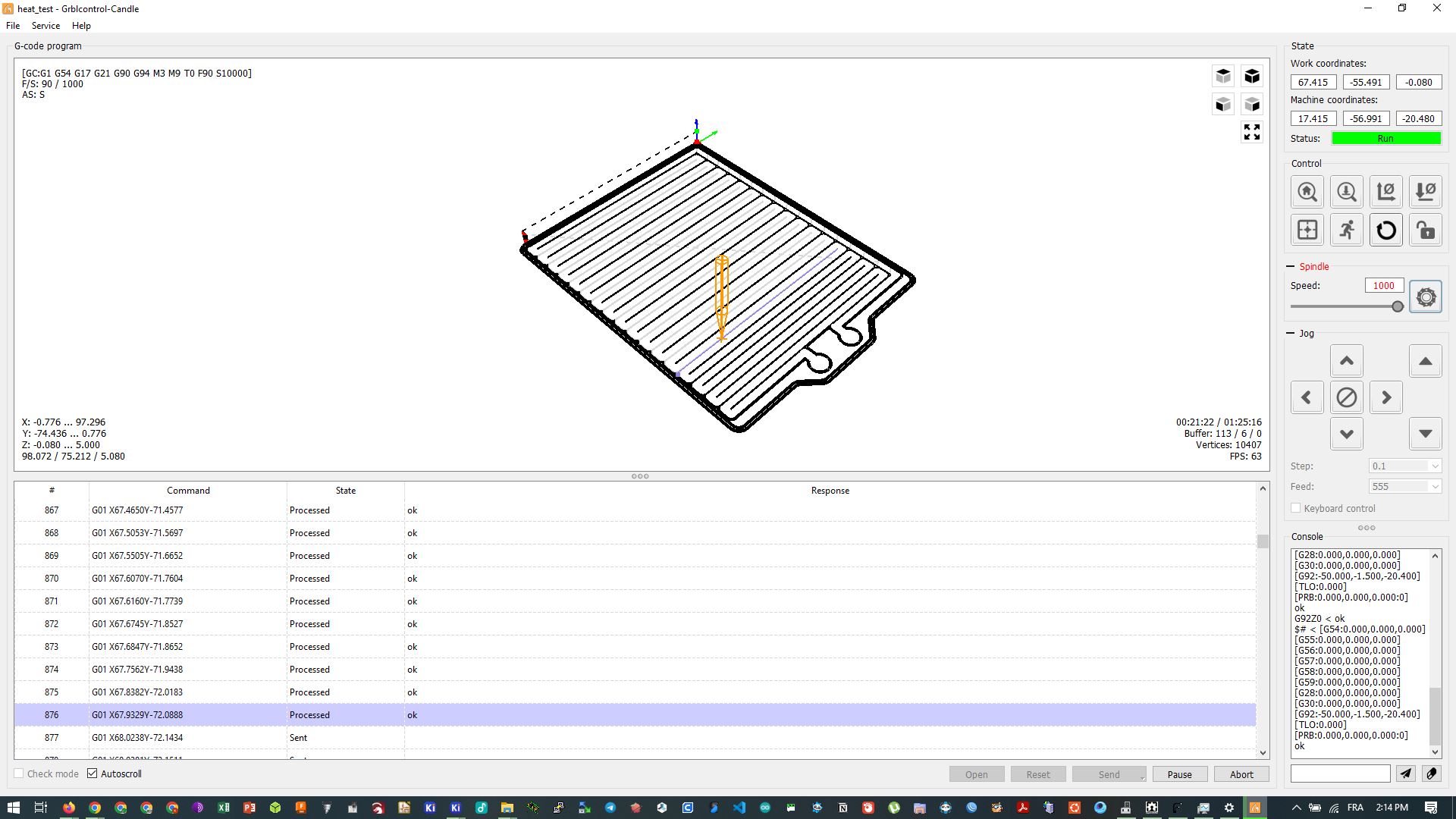
Milling the Joule PCB heater
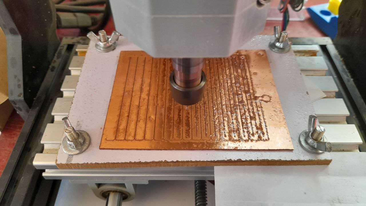
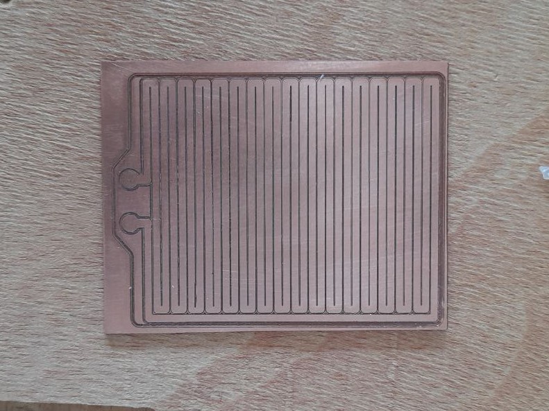
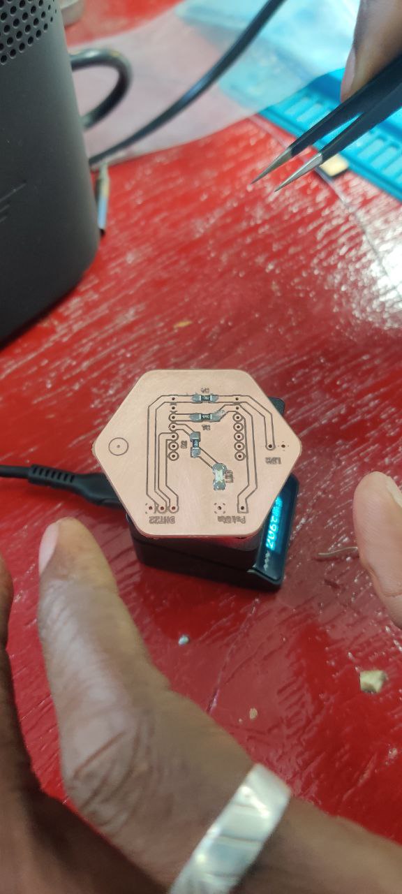
Result
Testing the Joule PCB heater
Issue And debugging:
- While milling with a CNC bed leveling can cause the part not to be milled as designed(Not Cutting trough....). With the pcb milling it can cause isolation routing not te go as planned. The best fix is to :
- Do a bed leveling involving use of probe for each job.
- Apart from that it’s good maintenance wise to do bed surfacing on our spoil board. This doe’s not replace bed leveling on job but helps.
- Since V bit tips are small they are also fragile and breaks a lot having a probe and Hight leveling helps Adjust the Z hight and solves the unmilled isolation that occur in tat situation.
- I have also made the mistake of milling my board without mirroring the file in Flatcam. Since my XIAO was going on the mon cooper side (mounting it with Pin socket) I have to mirror for it to be what I have designed.
- Here is a tutorial on how to do Hight Map in Candle