Embedded programming
Group assignment
My key takeaways for the board comparison
the XIAO ESP32 has more memory (SRAM and Flash) than the SAMD21 and the RP2040. in terms of Processor it ranks first compare to the AND21 but even if the RP2040 has 27MHz less it is a dual-core.
it also has WiFi and Bluetooth 5 Low Energy. they all have I2C/UART/SPI but the ESP32 have I2S. The rest is compatible with python whereas the ESP32 is just compatible with Arduino.
Board comparison table (From the XIAO Documentation WebSite)
| Item | Seeed Studio XIAO ESP32C3 mine | Seeeduino XIAO | Seeed XIAO RP2040 |
|---|---|---|---|
| Processor | ESP32-C3 32-bit RISC-V @160MHz | SAMD21 M0+@48MHz | RP2040 Dual-core M0+@133Mhz |
| Wireless Connectivity | WiFi and Bluetooth 5 (LE) | N/A | N/A |
| Memory | 400KB SRAM, 4MB onboard Flash | 32KB SRAM 256KB FLASH | 264KB SRAM 2MB onboard Flash |
| Built-in Sensors | N/A | N/A | N/A |
| Interfaces | I2C/UART/SPI/I2S | I2C/UART/SPI | I2C/UART/SPI |
| PWM/Analog Pins | 11/4 | 11/11 | 11/4 |
| Onboard Buttons | Reset/ Boot Button | N/A | Reset/ Boot Button |
| Onboard LEDs | Charge LED | N/A | Full-color RGB/ 3-in-one LED |
| Battery Charge Chip | Built-in | N/A | N/A |
| Programming Languages | Arduino | Arduino/ CircuitPython | Arduino/ MicroPython/ CircuitPython |
Individual Assignment
For this week’s assignment, I picked the ESP32 board
 To start I went To seeed studio’s getting started page
From the documentation I have got the following relevant information
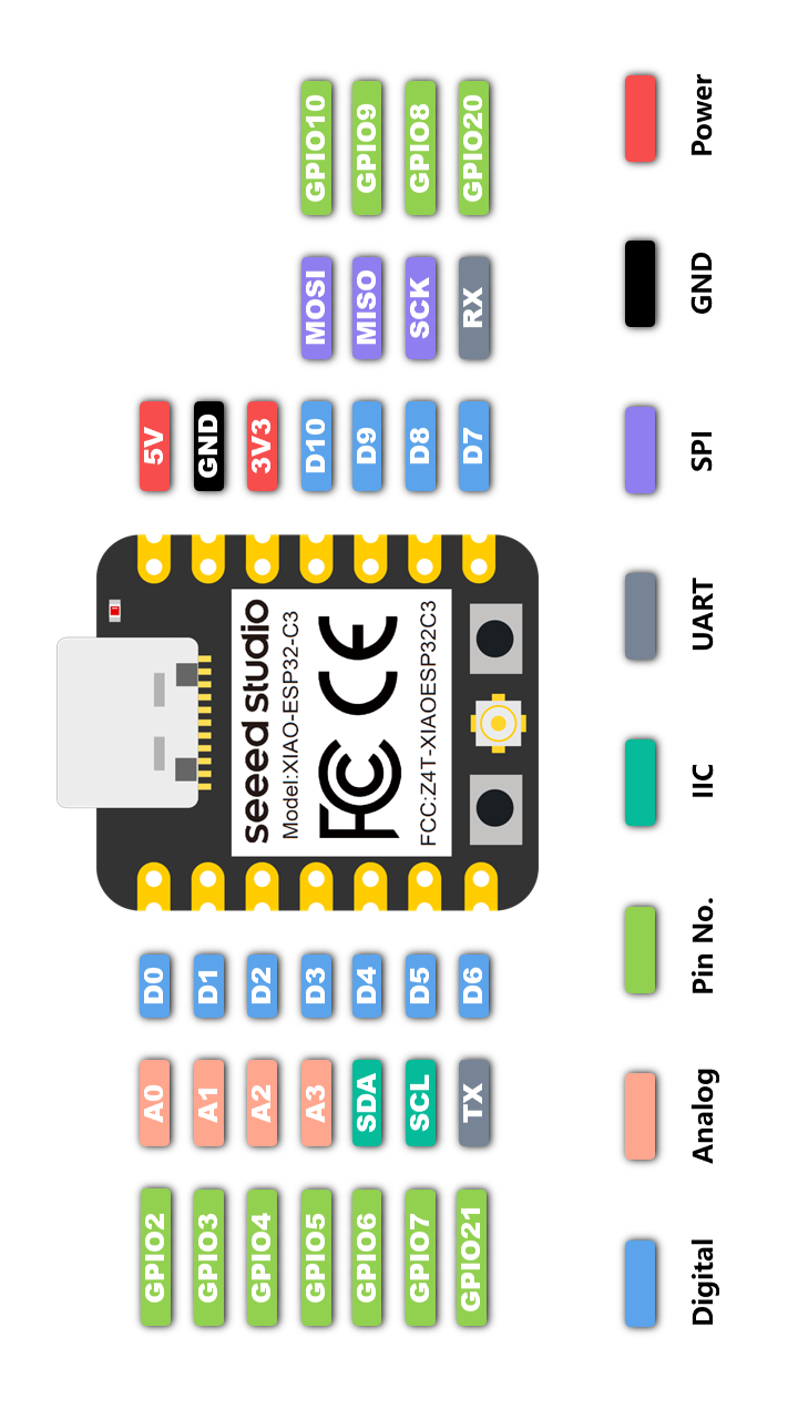
XAIO ESP32 Features
- Powerful CPU: ESP32-C3, 32bit RISC-V singlecore processor that operates at up to 160 MHz
- Complete WiFi subsystem: Complies with IEEE 802.11b/g/n protocol and supports Station mode, SoftAP mode, SoftAP + Station mode, and promiscuous mode
- Bluetooth LE subsystem: Supports features of Bluetooth 5 and Bluetooth mesh
- Ultra-Low Power: Deep sleep power consumption is about 43μA
- Better RF performance: External RF antenna included
- Battery charging chip: Supports lithium battery charge and discharge management
- Rich on-chip resources: 400KB of SRAM, and 4MB of on-board flash memory
- Ultra-small size: As small as a thumb(20x17.5mm) XIAO series classic form-factor for wearable devices and small projects
- Reliable security features: Cryptographic hardware accelerators that support ES-128/256, Hash, RSA, HMAC, digital signature and secure boot
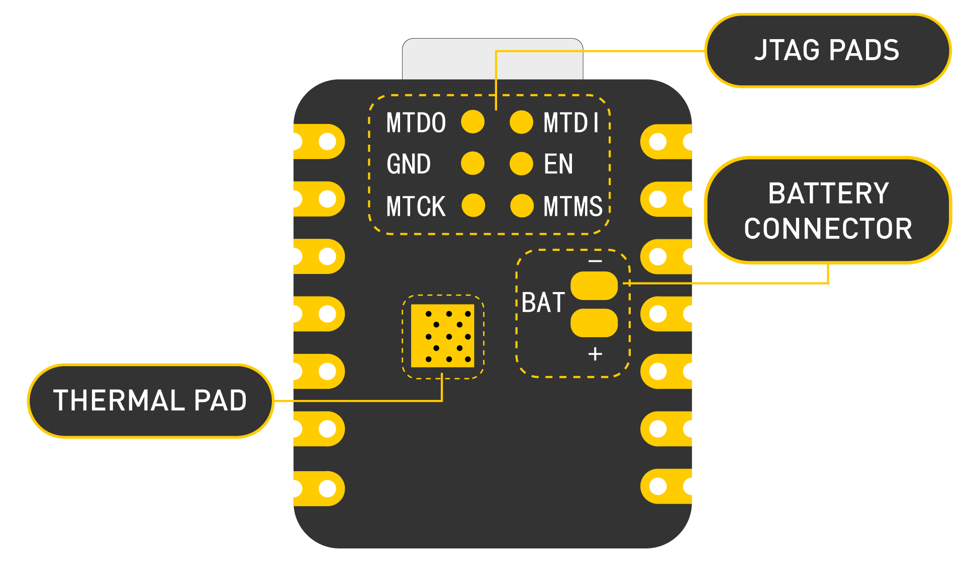
- Rich interfaces: 1xI2C, 1xSPI, 1xI2S, 2xUART, 11xGPIO(PWM), 4xADC, 1xJTAG bonding pad interface
- Single-sided components, surface mounting design
one thing that I have liked is the fact that I can add a battery to my project and the board will handle charging and safe use as it has an internal Battery charging chip that supports lithium battery charge and discharge management
Uploading my codes to the xiao board:
I will be using Arduino IDE to code and upload my codes to the board. First we need to follow the instructions on the #software-setup section on the seeed studio’s getting started page to install our board.
To Upload our codes :
* I connect my board to my computer using the usb cable
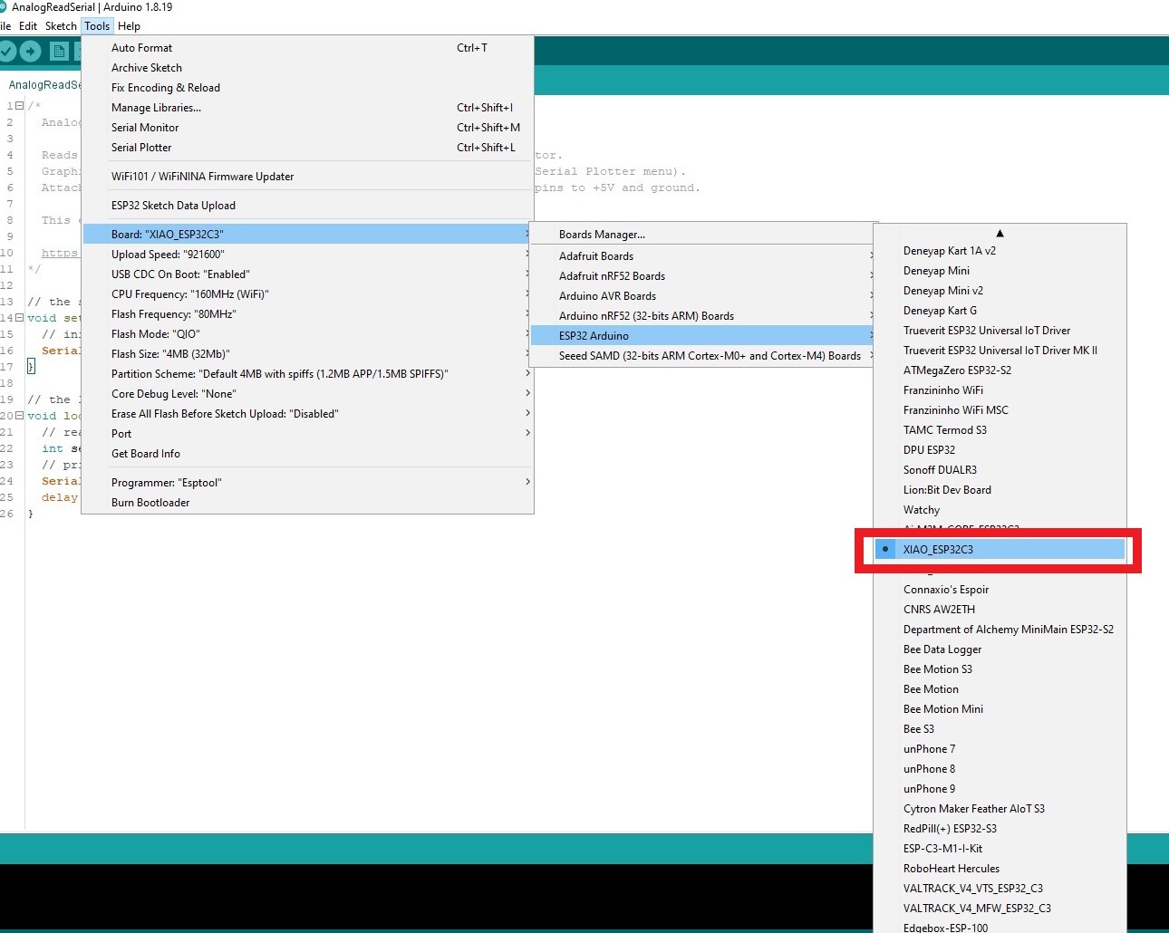
* Next I go to tools menu in arduino; then in board sub-menu, I chose ESP32 Arduino and scroll to select in th next drop down menu my bord which is XIAO_ESP32C3
*
- Next I go to Port (also under the tools menu) and I select the serial port of my board.
- Now I can upload my code to my board.
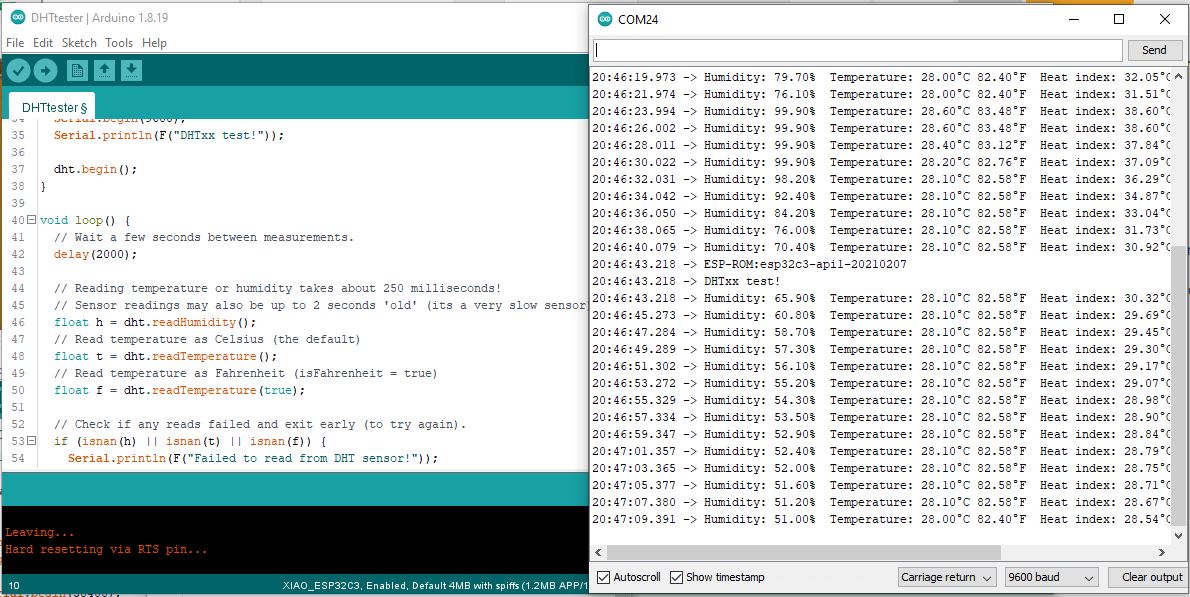
Testing a DHT22 humidity and temperature sensor
to do the test a used the default Adafruit Dhttester example code in which I just changed my sensor pin; in this case D1
Results of the DHT22 humidity and temperature sensor:
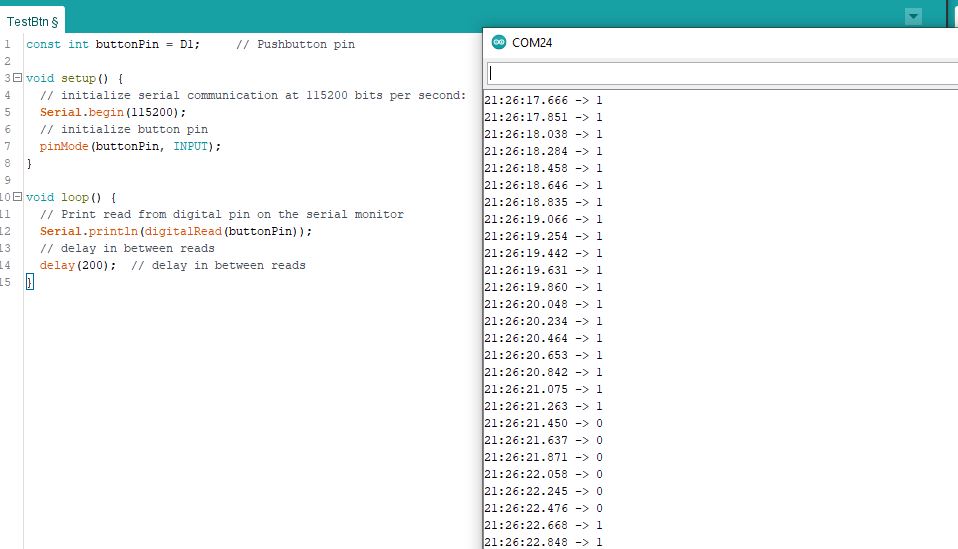
Reading a button state
I then tried a push button read. for that, I have added a pull-up resistor to keep it state high or 1 (this also help filter parasite signal). Pushing the button opens the ground connection making the read state LOW or 0
I have used the pull up despite my XIAO board having internal pull up because I want my board compatible with other dev board and microcontrollers that might not have the internal pull up. I might need to use another microcontrollers later due to local availability in my country or design choice.
        const int buttonPin = D1;     // Pushbutton pin

        void setup() {
            // initialize serial communication at 115200 bits per second:
            Serial.begin(115200);
            // initialize button pin as input
            pinMode(buttonPin, INPUT);
            }
        void loop() {
            // Print read from digital pin on the serial monitor
            Serial.println(digitalRead(buttonPin));
            // delay in between reads
            delay(200);
            }
Results of the reading the button State:
Using with Battery:
Unfortunately, My Esp wasn’t working powered with battery for now, and I couldn’t find why for the moment.
Blynk Trial:
What is Blynk
Blynk is an online platform that helps connect easily your IOT project online and also give you option to control device and monitor variables on a dashboard. You can even trigger actions from events… It has libraries and smartphone apps to helps you connect and was designed for the Internet of Things.
How Blynk Works
(Source https://blynk.io/ you can also check the new website https://docs.blynk.cc/from)
Blynk was designed for the Internet of Things. It can control hardware remotely, it can display sensor data, it can store data, visualize it and do many other cool things.
There are three major components in the platform:
Blynk App - allows to you create amazing interfaces for your projects using various widgets we provide.
Blynk Server - responsible for all the communications between the smartphone and hardware. You can use our Blynk Cloud or run your private Blynk server locally. It’s open-source, could easily handle thousands of devices and can even be launched on a Raspberry Pi. (my reaction here was: Fuyoooh !)
Blynk Libraries - for all the popular hardware platforms - enable communication with the server and process all the incoming and outgoing commands.
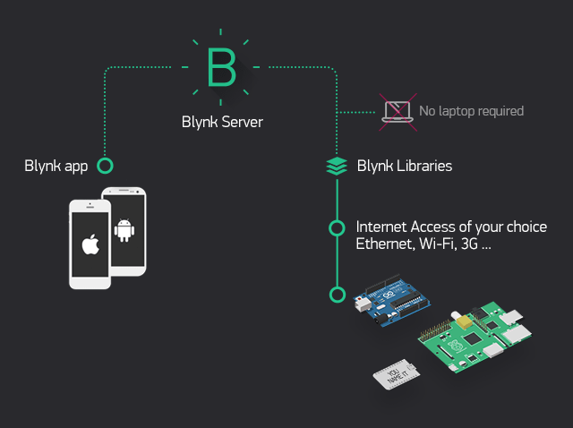
The process that occurs when someone presses the Button in the Blynk application is that the data will move to Blynk Cloud, where data magically finds its way to the hardware that has been installed. It works in the opposite direction and everything happens in a blink of an eye
Features
- Similar API & UI for all supported hardware & devices
- Connection to the cloud using:
- WiFi
- Bluetooth and BLE
- Ethernet
- USB (Serial)
- GSM…
- Set of easy-to-use Widgets
- Direct pin manipulation with no code writing
- Easy to integrate and add new functionality using virtual pins
- History data monitoring via SuperChart widget
- Device-to-Device communication using Bridge Widget
- Sending emails, tweets, push notifications, etc.
- … new features are constantly added! You can find example sketches covering basic Blynk Features. They are included in the library. All the sketches are designed to be easily combined with each other.
What I have done With Blynk :
Now, let’s try how to send sensor data online or to me. After a few searches, I discovered Blynk. I have tried it using getting started with Blynk guide. Then went on to get my create my token following manual device activation guide. And then how to display any sensor data in blynk app
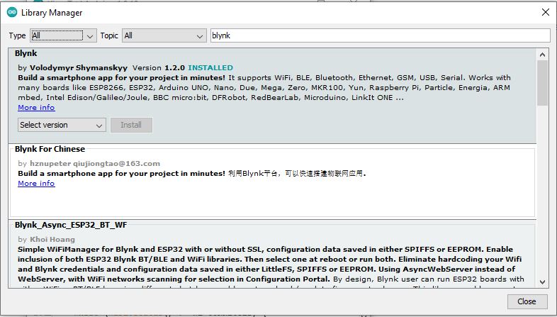
Installing the Blynk Library
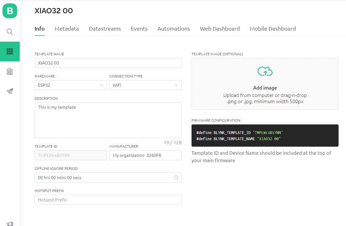
Template Creation and Getting the template ID
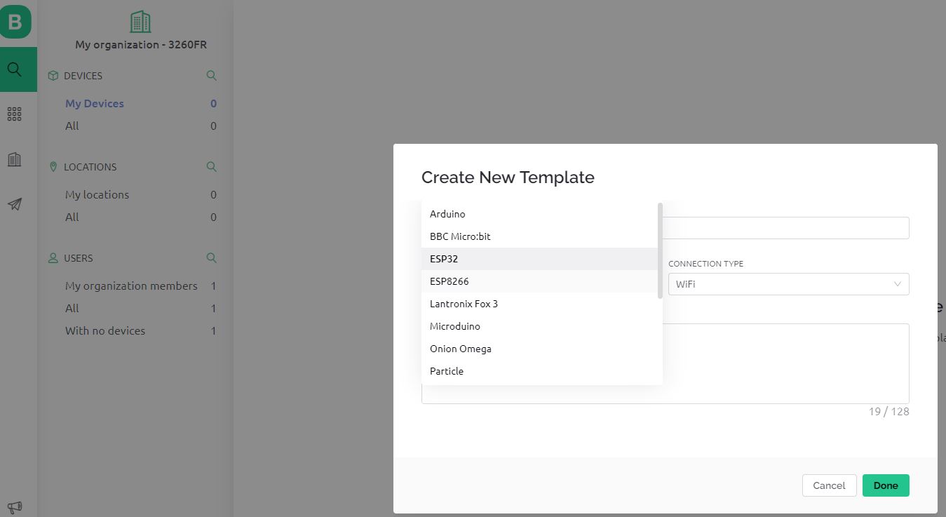
Template Creation and Getting the template ID
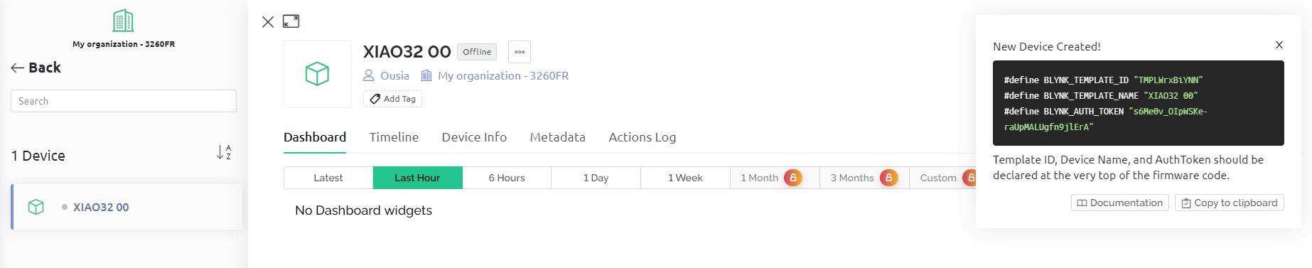
Adding device and getting Authentication Token
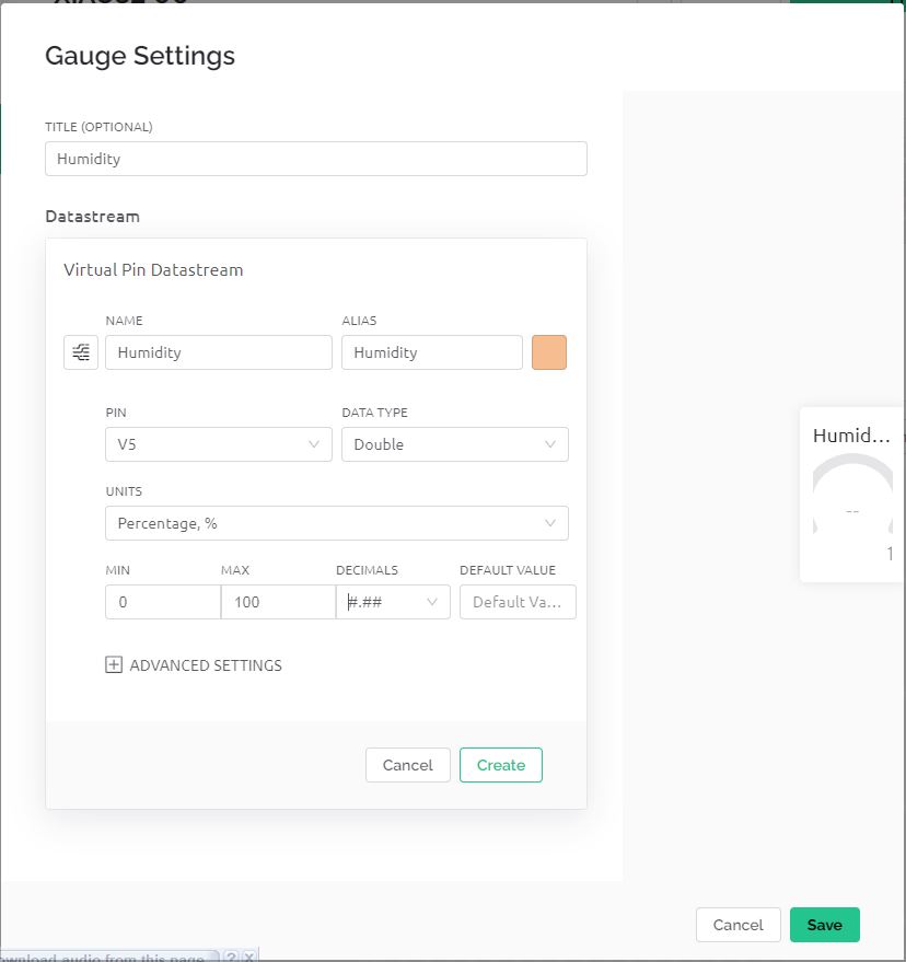
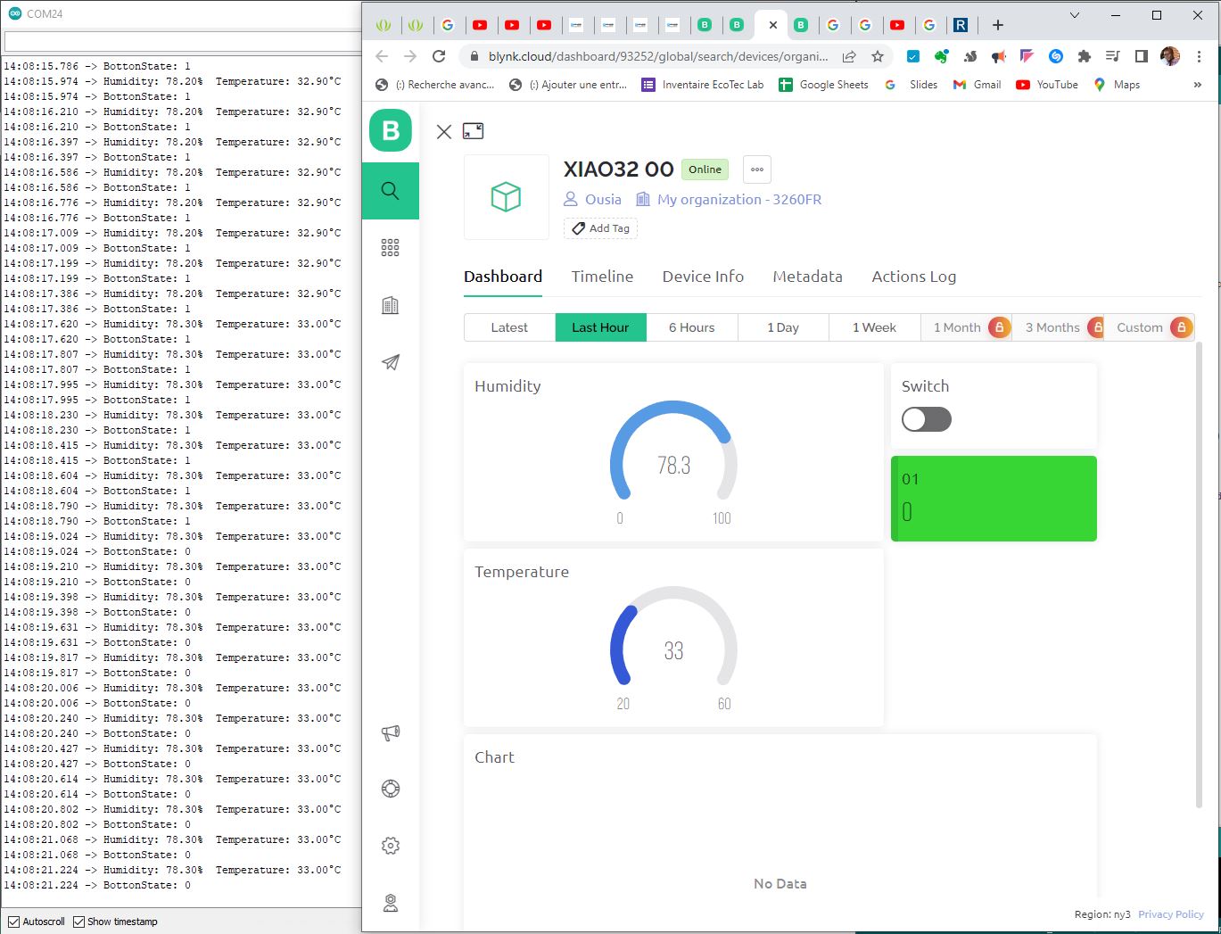
Adding element to my DashBoard
It seems Blynk readings are not consistent with serial output. A.K.A I have surely messed up somewhere
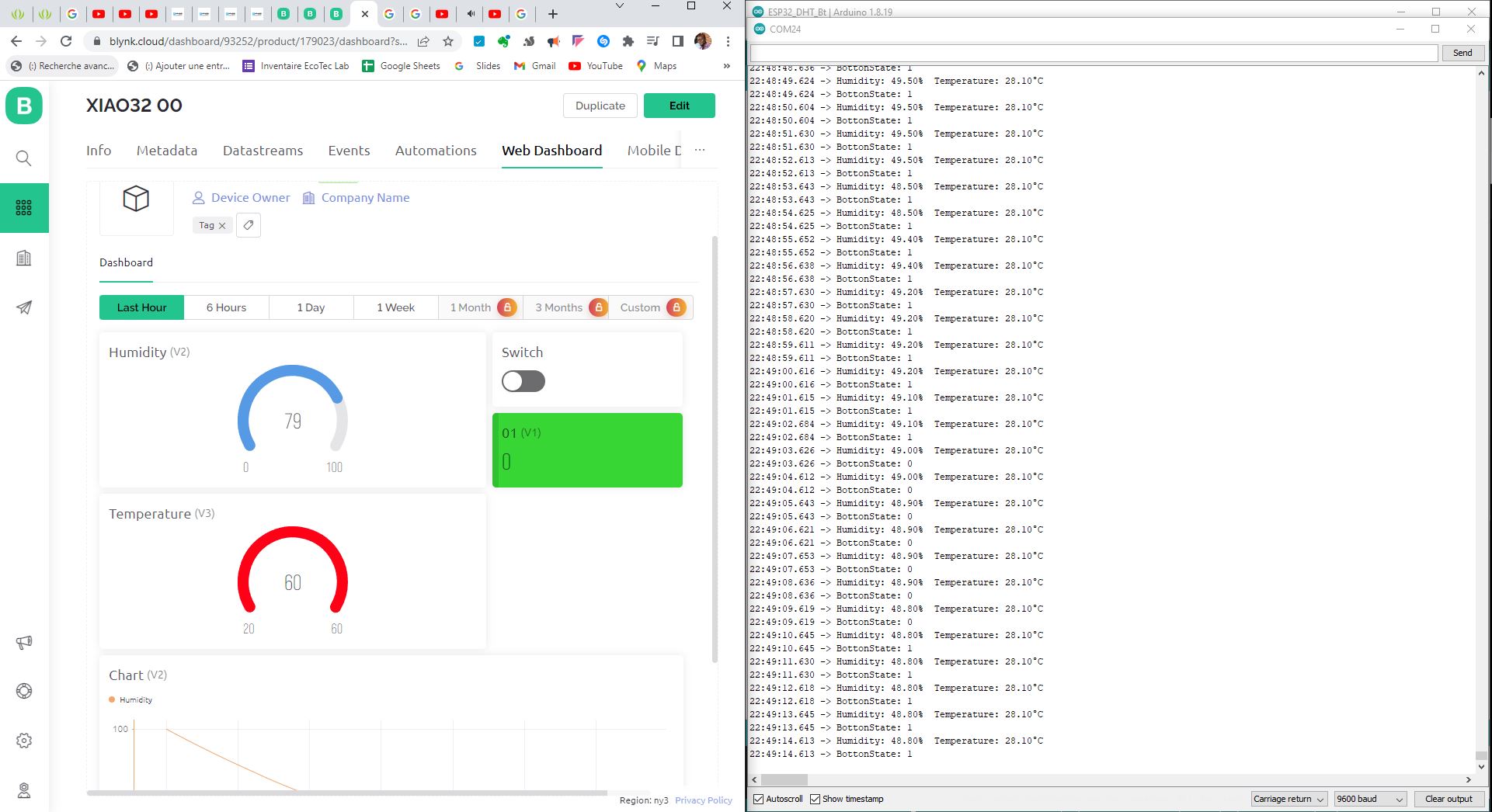
I went to my code and noticed I wasn’t sending the values to Blynk. So I have added the
sendSensor()
function to my void loop; The result below.
telegram bot Trial
After a few searches, I came across this tutorial ad modified the code.
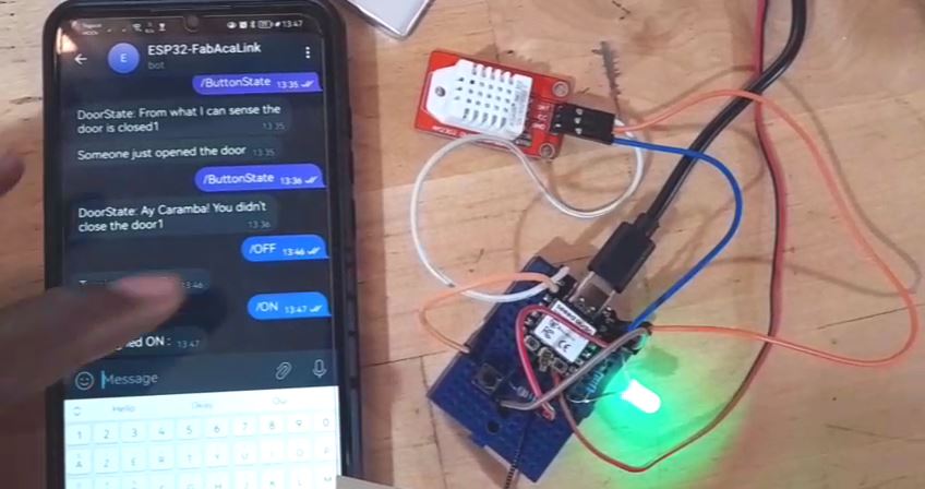
The process involved a telegram bot creation with token generation and getting my chat ID to allow secure communication with my bot. Meaning only allowed chat iDs can get readings from the bot.
What his Code does is read what is sent to the bot and answer accordingly. but if you send a command that it doesn’t know or wasn’t programmed for you simply get no reply.
Reading Button State
I have first added a code to read and send me my button state when requested. that code was added message handler on his code. the code was the following:
        if (text == "/ButtonState")
        {
                String Door = "";
                String msg = "DoorState:";
                        if (btn == 1)
                        {
                                Door = "Ay Caramba! You didn't Close the door";
                        }
                        else if (btn == 0)
                        {
                                Door = "From what I can sense the door is closed";
                        }
                msg += msg.concat(Door);
                bot.sendMessage(chat_id, msg, "");
         }
Button State Monitoring
Let’s send state changes from the hardware and send it to the bot without having to request it. For this I used a part of the code example from Arduino website I adde a void buttonSateChange() that I called upon in the loop.
void buttonSateChange() {
  // compare the buttonState to its previous state
  if (btn != lastButtonState) {
    // if the state has changed, increment the counter
    if (btn == HIGH) {
      // if the current state is HIGH then the button went from off to on:
      String msg = “Someone just opened the door”;
      bot.sendMessage(CHAT_ID, msg, ”");
      Serial.println(“opened”);
    }
    elseif (btn == LOW) {
      // if the current state is LOW then the button went from on to off:
      String msg = “Someone just closed the door”;
      bot.sendMessage(CHAT_ID, msg, "");
      Serial.println(“closed”);
    }
    // Delay a little bit to avoid bouncing
    delay(50);
  }
  // save the current state as the last state, for next time through the loop
  lastButtonState = btn;
}
Door State result from my smartphone screen recorder:
Turning LED ON from phone
Now that we can read from the device let’s order it to do something. Turning ON the LED attached to D10
LED Pin declaration before the void setup:
int led = D10;
Line added to the void handleNewMessages
 if (text == "/ON"){
        String msg = "Turning led ON :";
        bot.sendMessage(chat_id, msg, "");
        digitalWrite(led, HIGH);
}
if (text == "/OFF")
{
        String msg = "Turning led OFF :";
        bot.sendMessage(chat_id, msg, "");
        digitalWrite(led, LOW);
}
Controlling LED result from my smartphone screen recorder:
Picture of the result
Files
Arduino Sketch files: