Output Devices
Hero Shot
Group Assignment Page
http://fabacademy.org/2023/labs/energylab/group-assignments/output-devices/
How I determine the power consumption of an output device
For this part of the assignment we used a Fan as an output we have connected it to a power supply with voltmeter between it ground and Power pin. We also need the current so we connect the Amper meter in serie with the FAN(from the ground wire of the FAN to the Ground wire of the power generator)
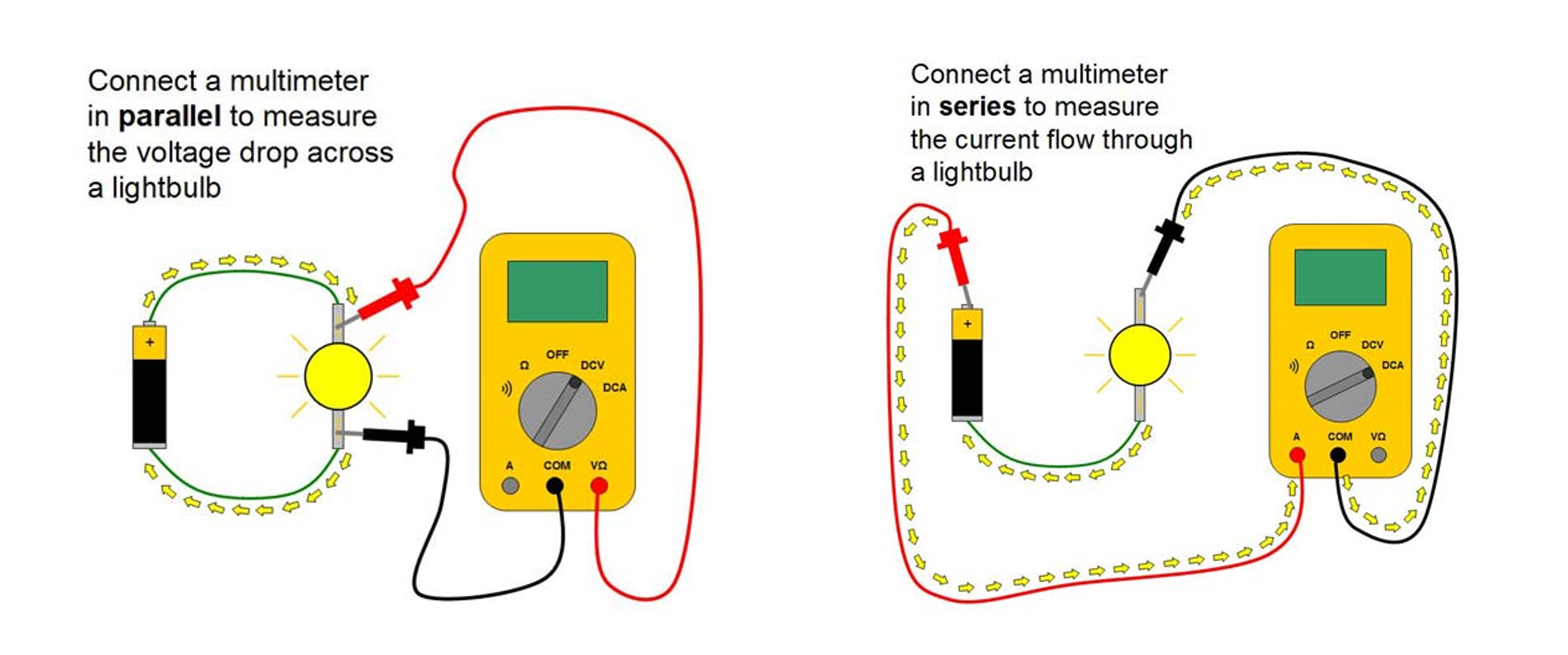
the power P is then calculated multiplying the voltage U read by the Current I read: P=U*I
in our case the Voltage was 12.24V and the current 190.3mA or 0.1903A so our Output FAN power is: 2.329 Watts
Individual Assignment
Why the use of the Dev bord in the video ?
This week I could milled my board time(before classes) as I was for from my node Lab. SO I used an Arduino Dev board from the assignment and later milled the designed boards bellow
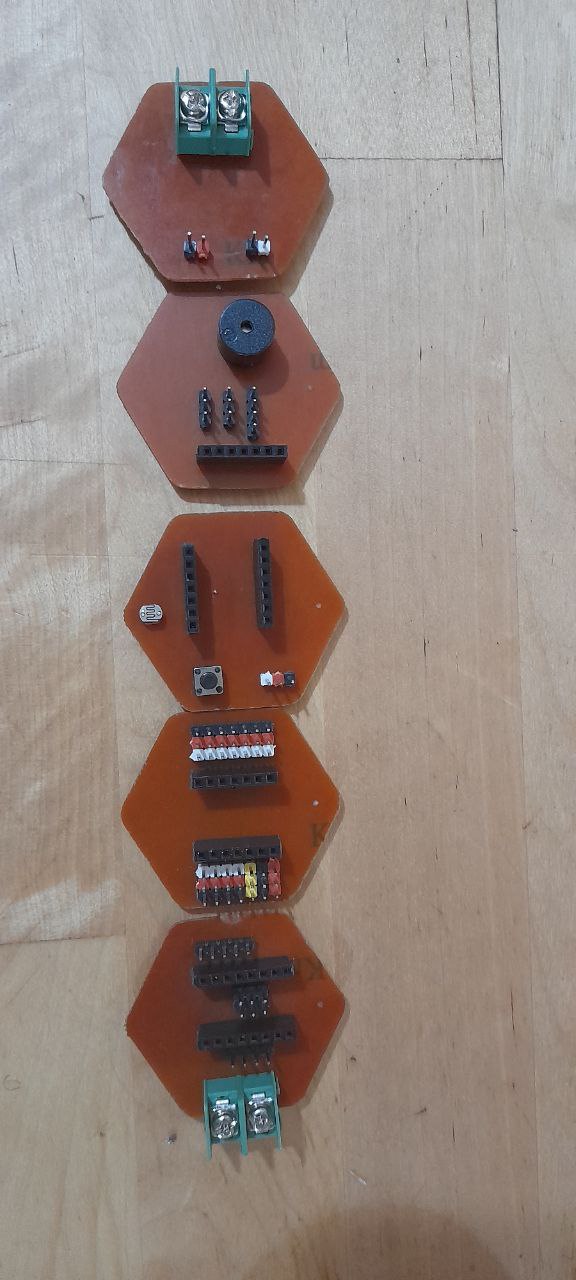
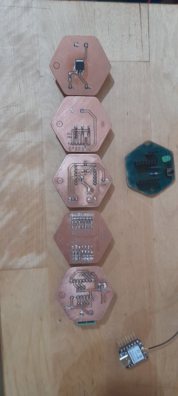
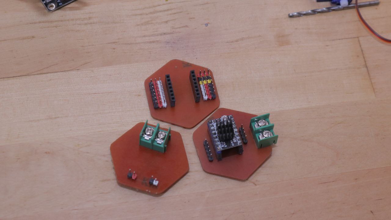
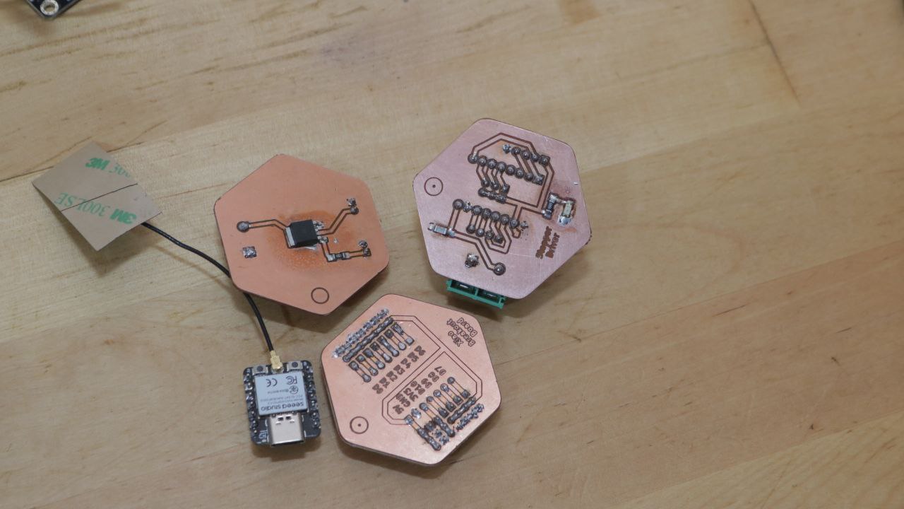
Board designed this week and milled later
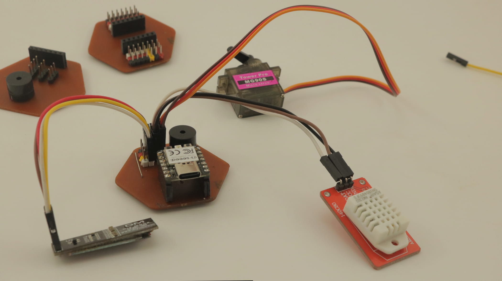
This week I have milled few output board to test part of may project and one specific for the output assignment. I have design and milled: * one stepper output board, (for test purpose for my final project) * PWM Mosfet Board (for test purpose for my final project), * An output board with a buzzer, connectors for a DHT22 sensor, an Oled Screen and a servo. * An output board with the previous components with socket to hst a XIAO Board. * There is also a last board that serves as Host for any Xiao board I will use for networking and other testing purpose.
LED
Controlling LED on week 04 using smart phone:
Buzzer
I have test the use of a buzzer to output sound and alerts. With Buzzer + Connected to Digital Pin 11 and ground connected to arduino’s GND. https://reference.arduino.cc/reference/en/language/functions/advanced-io/tone/
Code
  void setup() {
   // initialize the pin
   pinMode(11, OUTPUT);
}

void loop() {
   tone (11, 600); // turn on arduino active buzzer
   delay(500);
   tone(11, 900); // turn on arduino active buzzer
   delay(500);
   noTone(11);  // disable arduino active buzzer
   delay(500);
}
buzzer Code explanation
First in we configure pin 11 of the board as an output in the setup() for it toto send output signals to the buzzer.
In the loop() we use the tone() turn on an active buzzer connected to pin 11.this is done with the tone(11, 600) that generates a sound signal at a frequency of 600 Hz. After a 500-millisecond delay with the delay(500); we generate another sound signal at a frequency of 900 Hz with tone(11, 900); followed by another 500-millisecond delay. and for anoter 00-millisecond we use the noTone(11) function to deactivate the active buzzer.
Buzzer Result
LCD
Next I have used a 0.91” IIC I2C OLED 128x32 Display Module with Adfruit SSD1306 library. I have uploaded the example code to test it.
Using a servo
I test my servo using the exemple Sweep code in arduino. my servo was attached to the 8 pin.
 /* Sweep
 by BARRAGAN <http://barraganstudio.com>
 This example code is in the public domain.

 modified 8 Nov 2013
 by Scott Fitzgerald
 https://www.arduino.cc/en/Tutorial/LibraryExamples/Sweep
*/

#include <Servo.h>

Servo myservo;  // create servo object to control a servo
// twelve servo objects can be created on most boards

int pos = 0;    // variable to store the servo position

void setup() {
  myservo.attach(8);  // attaches the servo on pin 8 to the servo object
}

void loop() {
  for (pos = 0; pos <= 180; pos += 1) { // goes from 0 degrees to 180 degrees
    // in steps of 1 degree
    myservo.write(pos);              // tell servo to go to position in variable 'pos'
    delay(15);                       // waits 15 ms for the servo to reach the position
  }
  for (pos = 180; pos >= 0; pos -= 1) { // goes from 180 degrees to 0 degrees
    myservo.write(pos);              // tell servo to go to position in variable 'pos'
    delay(15);                       // waits 15 ms for the servo to reach the position
  }
}
Servo code explanation
After including the servo library with #include
then in our loop function a for loop increment the angle position variable pos from 0 to 180 degree; and writes each value of the position to the servo taking a 15 millisecond pause. making the servo moving in one Direction
  for (pos = 0; pos <= 180; pos += 1) { // goes from 0 degrees to 180 degrees
    // in steps of 1 degree
    myservo.write(pos);              // tell servo to go to position in variable 'pos'
    delay(15);                       // waits 15 ms for the servo to reach the position
  }
now we do the same but decreasing the position variable value to make it go backward.
  for (pos = 180; pos >= 0; pos -= 1) { // goes from 180 degrees to 0 degrees
    myservo.write(pos);              // tell servo to go to position in variable 'pos'
    delay(15);                       // waits 15 ms for the servo to reach the position
  }
servo as an output result
Putting it all together with a DHT22 sensor
We have them our outputs together with a DHT22 sensor. The idea is to take the sensor value and output the with the buzzer (making sound) and tha servo (Changing angle like on a gauge) and a screen to display the values.
Functions
- OLED: Display The sensor values
- The Buzzer map moisture level to a tone
- the Servo Map the temperature to angle
Code explanation
First before the setup we include our required libraries and declared variables:
* for the OLED screen that uses SPI.h, the wire.h, Adafruit_GFX.h, Adafruit_SSD1306.h
* we have also defined our Oled screen parameters.
c++
        #define SCREEN_WIDTH 128 // OLED display width, in pixels
        #define SCREEN_HEIGHT 32 // OLED display height, in pixels
        #define OLED_RESET     -1 // Reset pin # (or -1 if sharing Arduino reset pin)
        #define SCREEN_ADDRESS 0x3C ///< See datasheet for Address; 0x3D for 128x64, 0x3C for 128x32
        Adafruit_SSD1306 display(SCREEN_WIDTH, SCREEN_HEIGHT, &Wire, OLED_RESET);
* For the DHT22 we use the DHT.h and define it pin, type and start a DHT object dht
```c++ #define DHTPIN 7
#define DHTTYPE DHT22 // DHT 22 (AM2302), AM2321
  DHT dht(DHTPIN, DHTTYPE);
  ```
-
Servo.h, Servo myservo to create the servo object. int pos = 0; a variable to store the mapped servo position
-
For the buzzer int buz = 0; a variable to store the mapped buzzer frequency
We have then initialized everything in the setup and proceed to the Loop where :
* we start by clearing the values on the screen, set the font size, color an text cursor position.
* we have the declare a float variable to store the humidity values from the Dht and another on name t fro the temperature. there is a if function that check both variable value and if it’s a nom numeric value let’s us know that some thing is wrong in the DHT reading (either bad connection, or faulty sensor, bad pin definition....)
* Now we proceed to map the two variables to our main output the servo and the buzzer variables with
c++
      buz = map(h, 0, 100, 100, 1000);
      pos = map(t, 25, 75, 0, 130);
We then write the servo position value mapped to it and use the mapped buzzer frequency between 100 and 1000Hz and the alarm() function use it to output a tone.
c++
      myservo.write(pos);              // tell servo to go to mapped position in variable 'pos'
      delay(15);
      alarm();
- The void alarm Function :
void alarm() {
  tone(11, buz); // turn on arduino active buzzer
  delay(500);
  noTone(11);  // disable arduino active buzzer
  delay(500);
}
The Code
#include <SPI.h>
#include <Wire.h>
#include <Adafruit_GFX.h>
#include <Adafruit_SSD1306.h>

#include "DHT.h"

#include <Servo.h>

Servo myservo;  // create servo object to control a servo
// twelve servo objects can be created on most boards

int pos = 0;    // variable to store the servo position

int buz = 0;    // variable to store the servo position
#define SCREEN_WIDTH 128 // OLED display width, in pixels
#define SCREEN_HEIGHT 32 // OLED display height, in pixels
#define OLED_RESET     -1 // Reset pin # (or -1 if sharing Arduino reset pin)
#define SCREEN_ADDRESS 0x3C ///< See datasheet for Address; 0x3D for 128x64, 0x3C for 128x32
Adafruit_SSD1306 display(SCREEN_WIDTH, SCREEN_HEIGHT, &Wire, OLED_RESET);


#define DHTPIN 7
#define DHTTYPE DHT22   // DHT 22  (AM2302), AM2321

DHT dht(DHTPIN, DHTTYPE);

void setup() {
  myservo.attach(8);  // attaches the servo on pin 8 to the servo object

  // initialise les broches du Buzzer
  pinMode(11, OUTPUT);
  Serial.begin(9600);
  dht.begin();
  Serial.println(F("DHT Ready to go!"));
  // SSD1306_SWITCHCAPVCC = generate display voltage from 3.3V internally
  if (!display.begin(SSD1306_SWITCHCAPVCC, SCREEN_ADDRESS)) {
    Serial.println(F("SSD1306 allocation failed"));
    for (;;); // Don't proceed, loop forever
  }

  display.display();
  delay(1000); // Pause for 2 seconds

  // Clear the buffer
  display.clearDisplay();
}

void loop() {
  display.clearDisplay();
  display.setTextSize(2); // Draw 2X-scale text
  display.setTextColor(SSD1306_WHITE);
  display.setCursor(0, 0);

  float h = dht.readHumidity();
  // Read temperature as Celsius (the default)
  float t = dht.readTemperature();
  if (isnan(h) || isnan(t)) {
    Serial.println(F("Failed to read from DHT sensor!"));
    return;
  }
  buz = map(h, 0, 100, 100, 1000);
  pos = map(t, 25, 75, 0, 130);
  myservo.write(pos);              // tell servo to go to mapped position in variable 'pos'
  delay(15);

  display.print(F("Hr: "));
  display.print(h);
  display.println(F("%"));
  display.print(F("T: "));
  display.print(t);
  display.println(F("C"));
  display.display();
  delay (1000);
  display.clearDisplay();

  Serial.print(F("buz: "));
  Serial.print(buz);
  Serial.print(F("Angle: "));
  Serial.println(pos);

  Serial.print(F("Humidity: "));
  Serial.print(h);
  Serial.print(F("%  Temperature: "));
  Serial.print(t);
  Serial.println(F("°C "));

  alarm();

}

void alarm() {
  tone(11, buz); // turn on arduino active buzzer
  delay(1000);
  noTone(11);  // disable arduino active buzzer
  delay(500);
}
Issue and Debugging / what I have learned
Programming went well a had to use a development board fist because I didn’t managed to mill my board before my first commit but finally did and added it. I have Also made error in the PWM power output design but solved it later ( Fly wheel diode and a resistor missing). This was the goal of milling all those board and it’s good that I didn’t have to mill a bigger board like the one for my final project before noticing it.