Networking and communications
Hero Shot
Group Assignment :
Networking and communication - Group Assignment :
Individual Assignment overview:
design, build, and connect wired or wireless node(s) with network or bus addresses
My take away on I2C communication
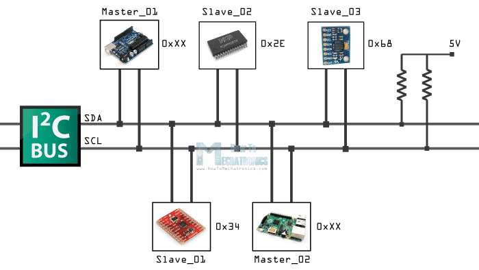
The I2C protocol, or Inter-Integrated Circuit, is a serial communication protocol used to connect multiple devices to a microcontroller, such as Arduino. It uses two wires, SDA (Serial Data Line) for data and SCL (Serial Clock Line) for clock.
The operation of I2C is based on Primary-Secondary (master-slave) communication. The microcontroller acts as a master, controlling data flow to attached secondary (slave) devices. Each secondary (slave) device has a unique address assigned, allowing the primary (master) to select which device it wishes to communicate with.
When I2C communication is initiated, the primary (master) sends a start signal, followed by the address of the secondary (slave) device it wishes to query. Then the data is transmitted, usually in bytes, between the primary (master) and the secondary (slave). The primary (master) generates clock signals to synchronize the transmission.
Primary/Secondary (previously Master/Slave) terminology
Primary
In I2C (Inter-Integrated Circuit) communication, the primary device is the one that initiates and controls the communication on the bus. It generates the clock signal, addresses the Slave devices, and controls the data transfer.
Secondary
On the other hand, the Slave devices are the peripherals or components that respond to the commands or requests from the Master. They wait for instructions from the Master and provide data or perform actions accordingly.
More on I2C
The I2C protocol uses a two-way transmission method, which means that the same lines are used to send and receive data. The Primary controls the direction of the communication by switching from a write transmission to a read transmission.
After each byte of data, the secondary device sends an acknowledgment signal (ACK) to the Primary to indicate that it has successfully received the data. If the secondary device does not respond with an ACK, this may indicate a communication error.
After all data has been transmitted, the Primary sends a stop signal to end the I2C communication.
The I2C protocol is widely used because it allows multiple devices to be connected with a minimum number of wires, thus saving pins on the microcontroller. Additionally, the ability to share a data line among multiple devices simplifies circuit design.
Now understanding the basics of the I2C protocol, you can easily interact with various sensors, modules, and other devices using this communication standard, leveraging the capabilities of Arduino and connecting different boards and projects together.
More on : www.circuitbasics.com/basics-of-the-i2c-communication-protocol
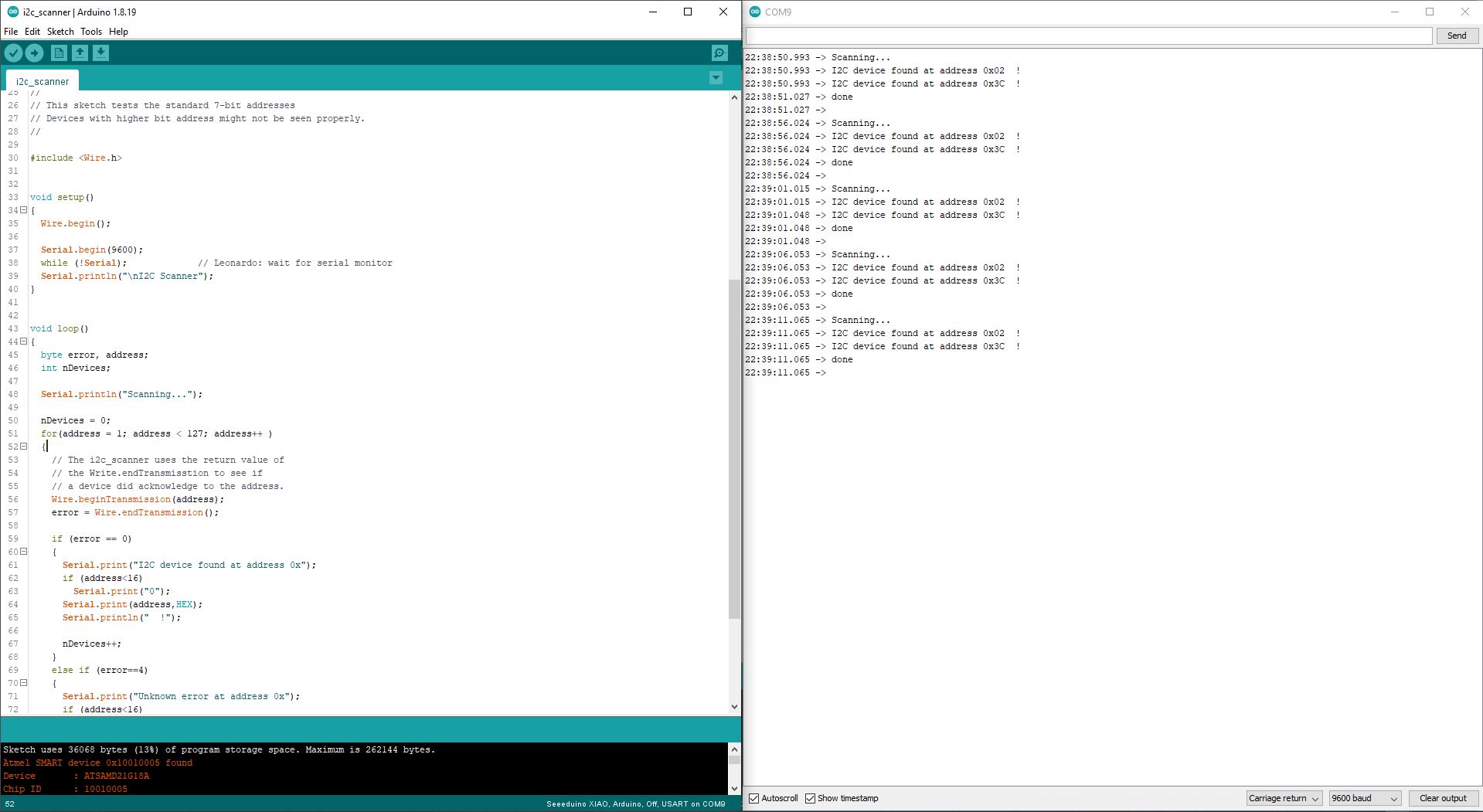
Finding device i2C address
My design this week hve an i2C lcd Connected so I have used the I2C scanner to find it’s address to avoid conflict setting the other devices I2C address. Sometimes it’s on the devices or can be found in their datasheet.
https://playground.arduino.cc/Main/I2cScanner/
Picture of the I2cScanner result:
Implementation of the I2C between two boards.
In my setup I have a secondary board that serves as an input. It reads Value from a DHT22 sensor and sends it to the Primary bard for output. The Input and Output board and code are from my respective previous assignments on that topic. more What they do here:
Secondary (slave) I2C Code and explanation
In the code for the secondary board we have defined it’s abus address (#0x02 OLED Screen is already On 0x3C) making sure it is different from th other i2c devices. This is done at the line
Wire.begin(2);
then we tell the board with action to trigger when request are made.
Wire.onRequest(requestEvent); // register event
After that we need to add a function that handles request for the Primary board
// function that executes whenever data is requested by master
// this function is registered as an event, in the setup()
void requestEvent() {
  Wire.write(temperatureC);
}
The secondary (slave) I2C Code
//#Secondary I2C

#include <Wire.h>
#include "DHT.h"

#define DHTPIN D3
#define DHTTYPE DHT22   // DHT 22  (AM2302), AM2321

DHT dht(DHTPIN, DHTTYPE);

byte temperatureC;
byte humidity;

void setup()
{

  Serial.begin(9600);
  dht.begin();
  Wire.begin(2);                // join i2c bus with address #0x02 (OLED Screen is already On 0x3C)
  Wire.onRequest(requestEvent); // register event

}

void loop()
{
  humidity = dht.readHumidity();
  // Read temperature as Celsius (the default)
  temperatureC = dht.readTemperature();

  Serial.print(F("Humidity: "));
  Serial.print(humidity);
  Serial.print(F("%  Temperature: "));
  Serial.print(temperatureC);
  Serial.println(F("°C "));

  delay(500);
}

// function that executes whenever data is requested by master
// this function is registered as an event, in the setup()
void requestEvent() {
  Wire.write(temperatureC);
}
Primary (master) I2C Code and explanation
For the Primary board Buss Address is not mandatory. so we made it join without address :
Wire.begin(); // join i2c bus (address optional for master)
Then we can send requests with Wire.requestFrom(2, 1) where 2 is the secondary board we are requesting from and the next figure 1* is the the number of bytes to request.
Wire.requestFrom(2, 1); // Request temperature data from secondary  at 2
  if (Wire.available()) {
    temperature = Wire.read(); // Read temperature data from secondary
    Serial.print("Temperature from secondary : ");
    Serial.print(temperature);
    Serial.println(" C");
  }
Then if the information is available we process it with Wire.read()and save it to a variable.
The Primary Output board I2C Code
//#Primary I2C

#include <SPI.h>
#include <Wire.h>
#include <Adafruit_GFX.h>
#include <Adafruit_SSD1306.h>

#include <Servo.h>

Servo myservo;  // create servo object to control a servo
// twelve servo objects can be created on most boards

int pos = 0;    // variable to store the servo position

int buz = 0;    // variable to store the servo position
#define SCREEN_WIDTH 128 // OLED display width, in pixels
#define SCREEN_HEIGHT 32 // OLED display height, in pixels
#define OLED_RESET     -1 // Reset pin # (or -1 if sharing Arduino reset pin)
#define SCREEN_ADDRESS 0x3C ///< See datasheet for Address; 0x3D for 128x64, 0x3C for 128x32
Adafruit_SSD1306 display(SCREEN_WIDTH, SCREEN_HEIGHT, &Wire, OLED_RESET);


#define servoPin D3
#define buzzerPin D6

void setup() {
  myservo.attach(servoPin);  // attaches the servo on pin D3 to the servo object

  // initialise les broches du Buzzer
  pinMode(buzzerPin, OUTPUT);
  Wire.begin(); // join i2c bus (address optional for master)
  Serial.begin(9600);

  // SSD1306_SWITCHCAPVCC = generate display voltage from 3.3V internally
  if (!display.begin(SSD1306_SWITCHCAPVCC, SCREEN_ADDRESS)) {
    Serial.println(F("SSD1306 allocation failed"));
    for (;;); // Don't proceed, loop forever
  }

  display.display();
  delay(1000); // Pause for 2 seconds

  // Clear the buffer
  display.clearDisplay();
}

void loop() {
  byte temperature;
  Wire.requestFrom(2, 1); // Request temperature data from secondary  at 2
  if (Wire.available()) {
    temperature = Wire.read(); // Read temperature data from secondary
    Serial.print("Temperature from secondary : ");
    Serial.print(temperature);
    Serial.println(" C");
  }

  display.clearDisplay();
  display.setTextSize(2); // Draw 2X-scale text
  display.setTextColor(SSD1306_WHITE);
  display.setCursor(0, 0);


  buz = map(temperature, 0, 100, 100, 1000);
  pos = map(temperature, 25, 50, 0, 180);
  myservo.write(pos);              // tell servo to go to mapped position in variable 'pos'
  delay(15);

//  display.print(F("Hr: "));
//  display.print(h);
//  display.println(F("%"));
  display.print(F("T: "));
  display.print(temperature);
  display.println(F("C"));
  display.display();
  delay (1000);
  display.clearDisplay();

  Serial.print(F("buz: "));
  Serial.println(buz);
  Serial.print(F("Angle: "));
  Serial.println(pos);

//  Serial.print(F("Humidity: "));
//  Serial.print(h);
//  Serial.print(F("%  Temperature: "));
//  Serial.print(t);
//  Serial.println(F("°C "));

  alarm();

}

void alarm() {
  tone (buzzerPin, buz); // allume le buzzer actif arduino
  delay(500);
  tone(buzzerPin, buz); // allume le buzzer actif arduino
  delay(500);
  noTone(buzzerPin);  // désactiver le buzzer actif arduino
  delay(500);
}
Issues and troubleshooting
No particular problem this week apart of the fact that I have to later try sending multiple variables and connecting more than 3 boards together.