13. Output Devices
This week, I learned how to use output devices that I may use for my final project, and used a board that I made to control an output. In my group, I used a multimeter to measure the power consumption of an output device.
Group Work
In my group, I measured the power consumtpion of a NEMA 17 stepper motor, and graphed our data to make conclusions
Output 1. Motor
For my final project, I’m going to need some kind of DC motor to move the wagon forwards. While I don’t have the motor I want to use for the wagon yet, I found this large 12v motor in our lab. I decided that this was a good starting point, because I’ll have to use an external power supply in my final project, and I knew that I would have to for this 12v motor.
Wiring
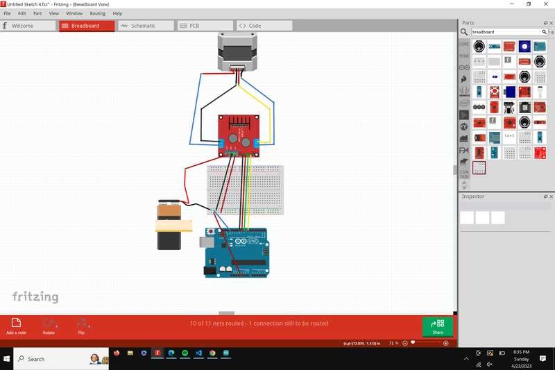
Because I’m using a DC motor, I needed to use a motor controller so that I can control the speed and direction of the motor. The motor driver I decided to use is the L298A motor driver. So, before I started wiring, I took a look at the datasheet and pinout for the driver. A couple of things that stood out to me were that there’s about a 2 volt drop between the input voltage and the output voltage to the motors, and that the maximum voltage for the driver is 57V, which is much larger than I plan on ever using. When I looked at the pinout, I felt that I understood it pretty well, so I began wiring. For the microcontroller, I decided to use the Fab Xiao, because I didn’t know if I wanted to mill a board for this ouput or a different one yet. One mistake that I caught early on was that at first, I didn’t connect the 2 control pins to analog pins on the microcontroller. These pins need to be analog so that the motor can be controlled at different speeds. My final wiring was Analog pin 0 and 1 to IN1 and IN2, 12 volts from a power supply into Vss, 5v from the microcontroller into Vs, and the 2 wires from the motor into OUT1 and OUT2. I found a library and used an example code, making sure to replace the pins from the example to the correct pins. However, the motor didn’t spin. When I tested the voltage going out to the motor, it read at 4 volts, even though I used a 12v power supply. I made sure that I had the Vs and Vss correct, and I still was only getting around 4 volts. I changed to a different power supply, and the motor then worked fine. I’m still not sure what my initial issue was.
Wiring Diagram for the 12v motor.
 The code I used
/*
Author  : Andrea Lombardo
Site    : https://www.lombardoandrea.com
Source  : https://github.com/AndreaLombardo/L298N/

Here you can see how to work in a common configuration.

Speed range go from 0 to 255, default is 100.
Use setSpeed(speed) to change.

Sometimes at lower speed motors seems not running.
It's normal, may depends by motor and power supply.

Wiring schema in file "L298N - Schema_with_EN_pin.png"
*/

// Include the library
#include <L298N.h>

// Pin definition
const unsigned int IN1 = 7;
const unsigned int IN2 = 8;
const unsigned int EN = 9;

// Create one motor instance
L298N motor(EN, IN1, IN2);

void setup()
{
  // Used to display information
  Serial.begin(9600);

  // Wait for Serial Monitor to be opened
  while (!Serial)
  {
    //do nothing
  }

  // Set initial speed
  motor.setSpeed(70);
}

void loop()
{

  // Tell the motor to go forward (may depend by your wiring)
  motor.forward();

  // Alternative method:
  // motor.run(L298N::FORWARD);

  //print the motor status in the serial monitor
  printSomeInfo();

  delay(3000);

  // Stop
  motor.stop();

  // Alternative method:
  // motor.run(L298N::STOP);

  printSomeInfo();

  // Change speed
  motor.setSpeed(255);

  delay(3000);

  // Tell the motor to go back (may depend by your wiring)
  motor.backward();

  // Alternative method:
  // motor.run(L298N::BACKWARD);

  printSomeInfo();

  motor.setSpeed(120);

  delay(3000);

  // Stop
  motor.stop();

  printSomeInfo();

  delay(3000);
}

/*
Print some informations in Serial Monitor
*/
void printSomeInfo()
{
  Serial.print("Motor is moving = ");
  Serial.print(motor.isMoving());
  Serial.print(" at speed = ");
  Serial.println(motor.getSpeed());
}
I also edited this code to only spin the motor forward, by removing the motor.backward(); command.
Buzzer
A buzzer might be useful to provide some feedback to the user for my final project, because they might not always be able to see the wagon.
Board
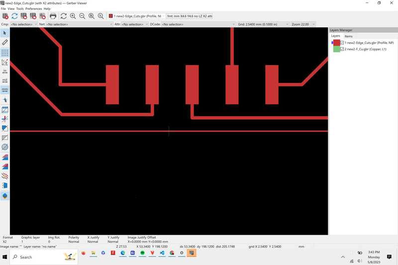
I already had a board with a buzzer as an output, but I milled a new one because I had ripped a pad on my board. I also changed the spacing on the pads for the headers so that they would fit better on the board, here’s what that looked like in the gerber viewer
Here’s what my board looks like soldered, I ripped one of the pads for the headers so I just soldered a wire directly onto the trace
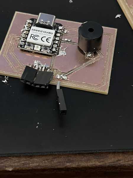
I then plugged in the board and uploaded a code to turn the buzzer on and off. However, the buzzer would only make clicking sounds. That’s when I realized that I was using a passive buzzer. An active buzzer only needs a DC signal to work, which is what I had the board to set up for. However, the passive buzzer on my board doesn’t have a built in component to generate an oscilating signal, so it needs an analog current to work.

Digital PWM
The buzzer on my board wasn’t connected to a pwm pin, however I found a solution to at least get the output to work. The rp2040 doesn’t have true analog outputs, but instead has PWM enabled pins. PWM stands for pulse width modulation, this was explained in our group sight when we looked at a PWM signal through an osciloscope. But, only some I/O pins are connected to an oscilator that allows PWM to work, and I didn’t have one of these pins connected to the buzzer. However, a pin can be toggled on and off to simulate a PWM signal. This is called SPWM, or software PWM. Here’s the code I used to generate a PWM signal to the buzzer at a 10% duty cycle. With this code, the buzzer worked.
void setup()
{
 pinMode(7, OUTPUT);
}

void loop()
{
  digitalWrite(7, HIGH);
  delayMicroseconds(100); // Approximately 10% duty cycle @ 1KHz
  digitalWrite(7, LOW);
  delayMicroseconds(1000 - 100);
  Delay(1000);
}
Software PWM isn’t often utilized because it’s not practical. If the output is running, nothing else can be processed in the background, and it’s hard to run the PWM pin at the desired duty cycle.
LCD
The last output I decided to experiment with for this week is an LCD screen. Because the Xiao Rp 2040 has a limited amount of I/O pins, I used an LCD with a built in microcontroller, so I only had to use the I2C, ground, and power pins.
Configuration
The board I milled from last week already had the proper connections, so I plugged the board with 5v to 5v, GND to GND, and SDA and SCL to the appropriate pins on the board. Before I was even able to look at code, the Seeed turned off, and when I plugged it in again it wouldn’t turn back on, I’m not exactly sure why this happened but I think I might have accidentally touched the power and ground pins and shorted the board. Because I didn’t have another board that utilized the Seeed Xiao rp2040, I switched to using a rasberry Pi Pico. The wiring was the same except the Pico has multiple I2C pins, so I chose SDA 0 and SCL 0. I tried to find a solution with using the I2C lcd in arduino, but the only tutorials I found were using Micropython and Thonny. This tutorial helped guide me through the initial setup process. To run the RP2040 with micropython. I first had to install Thonny, which is a beginner pyton interface that can be used with Micropython. The setup process was pretty simple, all I had to do was choose a download path. Once I was in Thonny, I plugged in the pico while holding down the BOOTSEL button. I had to wait a little for the device to be set up with my computer, but once I did I installed micropyton onto the pico by going to Run>Configure Interpreter>Install or update Micropyton, and selecting the USB device from the options. Once I did this, I had to add some code to the Pico that had details about the LCD screen and how to control it. All I had to do was copy the code from the tutorial, pasted it into a blank document, and then named and saved the code to the Pico. The tutorial displayed some text, the I2C address of the devices, and a backlighting test.
Code
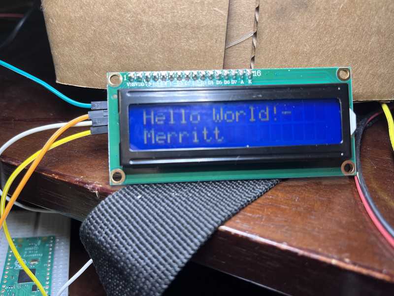
While the Tutorial had a code that displayed the I2C adress of the LCD and some other text, I made a simple one line code myself that just put some text on the screen. I ran the code and it displayed the text I put in.
Reflection
This week I learned a lot about using different output devices, as well as which ones need external driver boards or current to operate. In my group, I learned a lot about the relationship between Voltage, Power, and Resistance in an output device.