4.Electronics Production
This week I milled the board that I made last week during electronics design.
Group Work.
This week our group work we explored the theory behind machining different materials, and how to create intended results. My part of week 9 was defining terms used during milling.
Considerations
Software and machine
Our lab uses the Othermill Pro and the bantam equivilent. For materials we use single-sided FR1 PCB and use the 1/32 flat end mill, 1/64 flatt end mill, and .005” PCB engraving bits. For software, we use the Bantam Tools Miling Machine Software. There were no alternative options for any of these choices.
Parts
During electronics design week I already chose what parts I was going to use to mill this board. For the microcontroller I’m using the Seed Studio Xiao RP2040, a generic piezo buzzer, and the VL531X-Satel breakout board. Because there’s no way to directly connect the breakout board, I’m using male headers to connect to the breakout board. These parts will be placed on the design I made for my electronics design week.
Goals for this week
My goals for this week were to program my board to read input data from the TOF distance sensor and generate a corresponding output from the buzzer.
Milling
To mill I used the following workflow created by our lab: - Materials: - OtherMill Pro - Profile & Holes Bit - 1/32” Flat Endmill (Orange Cap) - Precise Trace Bit - 1/64” Flat Endmill (Precise Bits) 0.005” PCB Engraving Bit 15 degree Taper Stud this is - not a traditional tip - Collet wrenches - Foam for bed when changing bits - FR-1 PCB Board - Nitto Tape
- Preparation Phase: Bantam Tool
- Download file
- Geber
- Eagle.brd
- SVG
- KiCad Files
- Clean the Bed
- Use a vacuum and remove loose materials.
- Wipe down with alcohol
- Material
- Select material - generic or FR1 NOT FR4
- Measure the width and height of the conductive material you wish to mill (PCB - FR1)
- Enter the width and height values.
- Tape down the material
- Use Nitto tape (double-sided tape)
- No overlaps
- No wrinkles
- Make sure to put the tape away once done
- Open Bantam Software
- Load File
- Setup File
- Trace Depth: 0.20 mm
- Trace Clearance: 1.50mm (Note: you need to change this from the default setting of 0.15) Bits:
- 1/32” Flat Endmill
- 1/64” Flat Endmill - select this setting as opposed to 15 degree Taper Stud0.015” 15 degree
- PCB Engraving Bit 0.005”
- Probe Material Thickness using the Bit Breaker
- Pro Tip: Instead of using the arrow keys to move the spindle on bit breaker, use some GCode in the Debug tool Open the Debug tool by selecting the “Show Debug Console” in the BitBreaker menu (correction needed the G code to move the spindle needs to happen after you press the depth prob and “next”) To send the spindle to a specific X,Y coordinate use the following GCode command: G53G00X(Insert value)Y(Insert Value) G53G00X50Y60 will send the spindle to (50,60)
- When you are finished typing in the coordinates, click on the “Send Command” button to execute the command.
Click on “Probe Material” to find the material thickness.
Use the GCode to find the thickness in a grid where the board will be milled. - When milling multiple boards, use the minimum material thickness of all the points probed. Values can vary from 1.67-1.95mm, which matches the manufacturing tolerance of the board at +/- 0.15mm.
- Home Machine
- Prep Machine & Configure the job in Bantam Softwarethe Bantam Tool
- Select tool (end mill or engraving bit) by selecting change
- Choose tool under New Tool
- Install the tool by loosening collet and replacing tool
- Click continue
- Verify tool position
- Locate tool
- Milling the face of the board
- Setup the board in the Bantam Software and be sure “Trace and Holes” are selected. Be sure “Outline” is NOT selected
- Select the ‘PCB Engraving 0.005”’ tool
- Select the ‘1/64” Flat End Mill’
- Confirm there are no red areas on the face of the board in the Bantam Software.
- Verify only the parts to be milled are visible in the software
- Start milling using the “Mill All Visible” button.
- Follow-on screen instructions for inserting the correct bits
- To maximize bit life, be sure to place the white foam on board when changing or installing bits
- Be sure to periodically check the bits under the microscope before installing to confirm they are still sharp.
- Cutting Out the Board after milling the face:
- Deselect Traces and Holes in the Bantam Software
- Select Outline
- Add ‘1/32” Flat End Mill’ to the Milling Tools
- Confirm that only the board outline is visible
- Start milling using the “Mill All Visible” button.
- Follow-on screen instructions for inserting the correct bits
- To maximize bit life, be sure to place the white foam on board when changing or installing bits
- Be sure to periodically check the bits under the microscope before installing to confirm they are still sharp.
- Board Removal:
- Move the PCB board to the loading position and vacuum the board.
- Use the 5 in 1 paint scraper to remove the board from the machine.
- Vacuum inside the machine to get residual debris after the board is removed.
- Put all bits back in their original containers.
- Clean Up:
- Vacuum inside the machine to get residual debris after the board is removed. -Put all bits back in their original containers.
Images of workflow process, and descriptions of the workflow.
** Since I am returning to this week after rolling over, I will be documenting the process of milling my final project board.
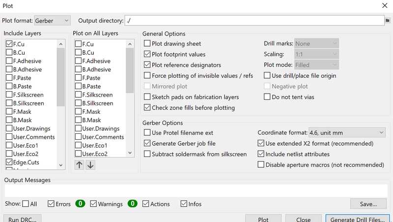
The Kicad manufacture window (accessed through file>manufacturing exports). I selected the gerber format for milling, and only selected the top copper and edge cuts, as I did not need any other parts of the footprints to be cut, like the silkscreen and solder mask.
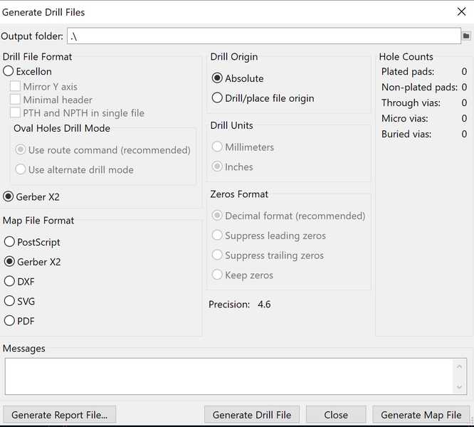
I also created a drill file for the through holes in my board, which only had one option for file part.
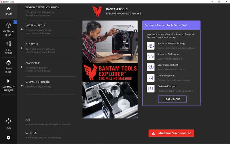
I then imported my file into the bantam tools workspace, this is the homepage of the software where I imported my file through the file setup tab.
When I loaded my files, I selected the top copper file as the Fcu gerber file, and the outline as the edge cuts gerber file, and then placed the design on the workspace
I then set up the file by changing the settings to a 1/32” ball end mill, a 1/64” ball end mill, and a .005” PCB engraving bit. I also set the trace depth to 0.2 mm and the trace clearence to 1.5mm, this setting clears more material in between traces, and decreases the likelyhood of a short or a solder bridge.
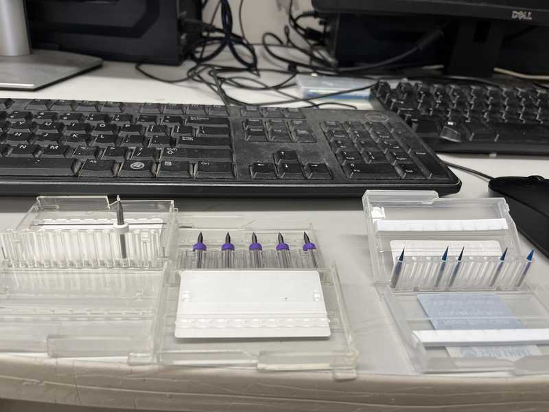 The 1/32”, The 1/64”, and .005 PCB engraving bits
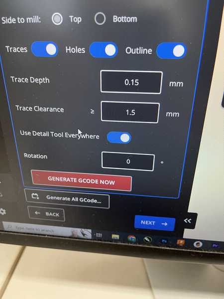
Setting the trace depth and clearence
Next, I attatched the copper with Nitto tape, a strong 2 sided tape. I used a one sided FR4 PCB, as FR3 PCBs release small copper fragments into the air which can cause health issues.
I then set the length of the bit, so the machine knows where the bit is. I did this by inserting the bit and selecting the “Tool Install” menu
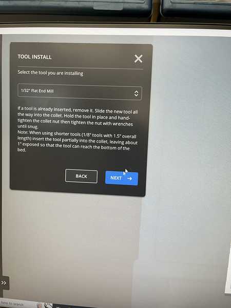
The tool install menu
The tool then touches the bottom of the machine bed to find the position of the bit.
Now that the machine knows where the tool is, I had to also set the position of the material, I did this through the probing menu
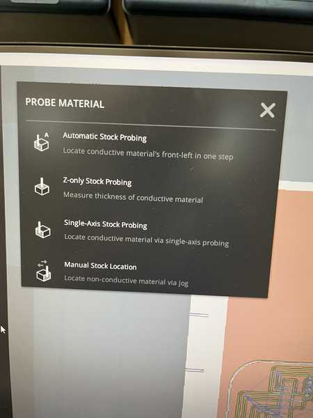
The probing menu, I selected the “Z-only stock probing” to measure the thickness of the board
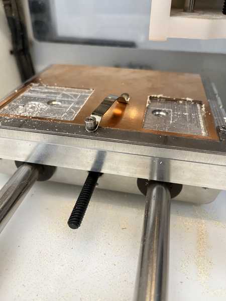
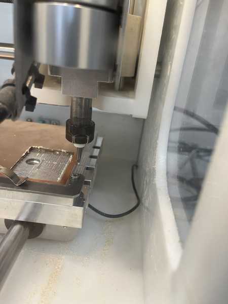
I then put the conductive clip on top of the material. This creates a circuit between the material and the machine, so when the bit touches the machine, there is an interuption to the signal. Using the position of the bit during this interrupt finds the thickness of the material.
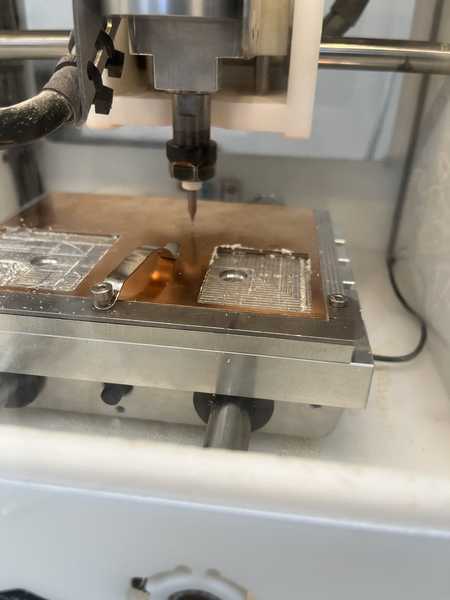
The bit touching off on the material
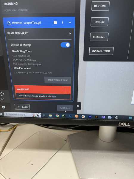
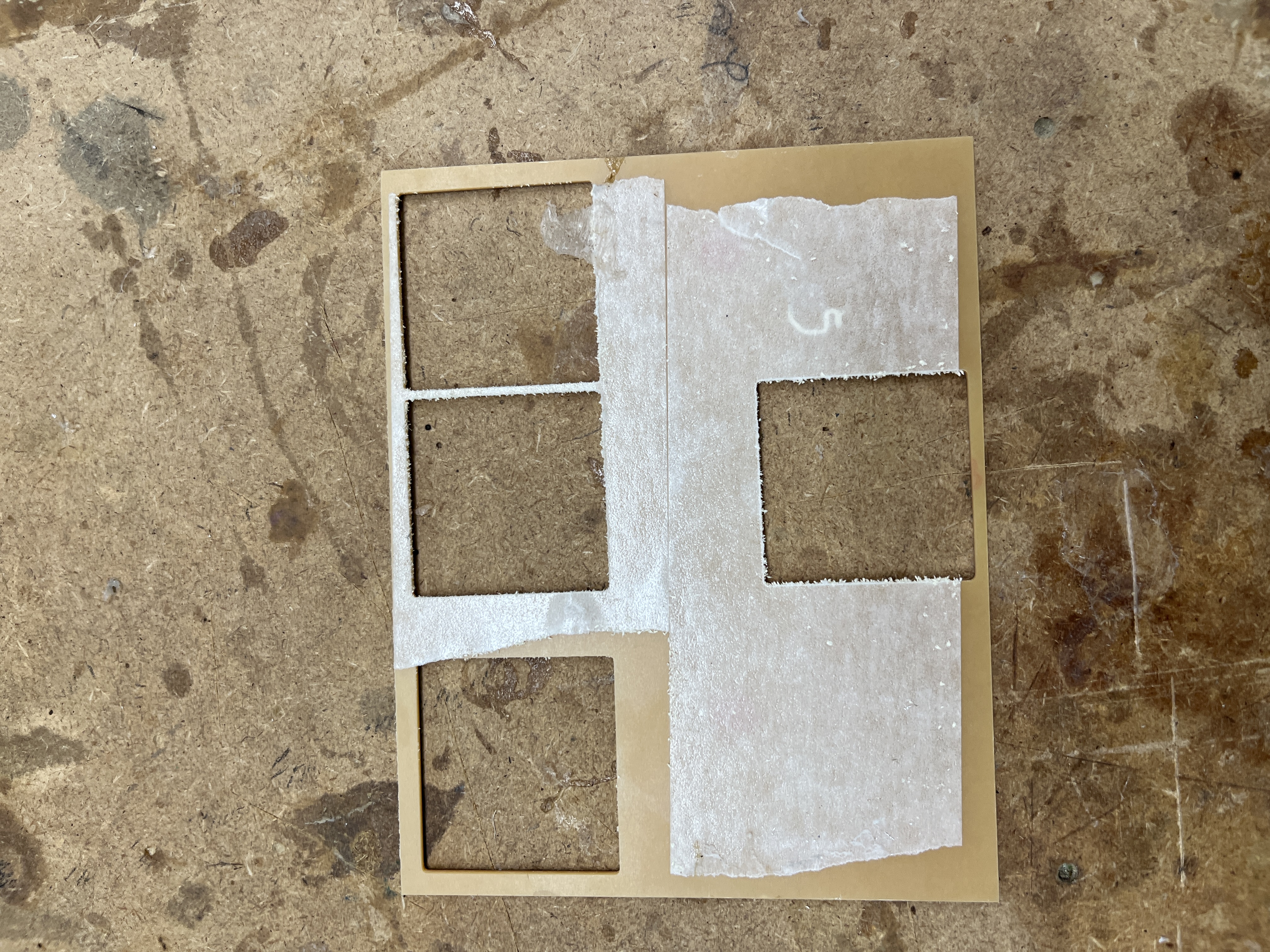
I then encountered a problem when trying to mill the board, the software gave a warning that a marked area needed a smaller tool to mill. I then went back to my design to see where this marked area is.
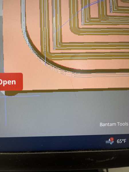
The marked area turned out to be this small part of the curved part of my board, where the clearence for a trace went into the edge cut. Because this isn’t an issue that will cause any problems with my board. I proceded to cut.
Heres a little of the 1/64” bit cutting the pads for the XIAO
Problems I faced
While I was able to avoid some of the more common problems, like forgetting to put the clip on the PCB material or not attatching the board correctly, I had another problem that took some troubleshooting. When I first tried to zero a bit, the machine moved down so far into the cut bed that the bit broke. I decided that instead of replacing the bit, I’d use the already broken bit to test some theory’s that I had. The first was that something was wrong with the conductivity system that measures when the probe touches the bed, this problem could be wrong from the point of the bed or the spindle. To test if it was on the spindle side, I went through the process of finding the material thickness. When I did this, the same thing happened, and I had to hit the emergency stop button to stop the Z axis from moving further. When I reset the machine after hitting the stop button, it had to re home itself. I realized that this was most likely the problem in the first place, the Z axis could have somehow been reset so the machine believed it was higher than it actually was. After resetting, I was able to find the toolpath.
What I learned
I learned a few major skills from this week. This is the first week where I have really used a machine that I am unfamilliar with, so all the skills of using the Bantam are new to me, such as changing tools, setting the zeros of the machine, inserting and calibrating my materials, and cleaning up the machine. In the group project I learned some of the working principles behind PCB milling, such as chip load, types of cutting tools, and effective clearences of different types. This machine has the most steps to use that I have learned so far, and after making my mistake described above, I learned to be extra dilligent with reading and following workflows for machines I am unfamilliar with.
Soldering
To Solder my board I used a mix of techniques for the surface mount and through hole parts of my design. For surface mount soldering the XIAO, I preferred to first put solder paste on the opposite corners, and then heating them up. This provided enough of an attatchment that I could use regular solder for the rest of the board. For the headers, I put the headers onto a breadboard upside down so that they would stay straight, and then put solder on all of the headers. Because I had 2 ground pins that were intentionally attatched, I intentionally bridged the 2 holes to provide a better connection.
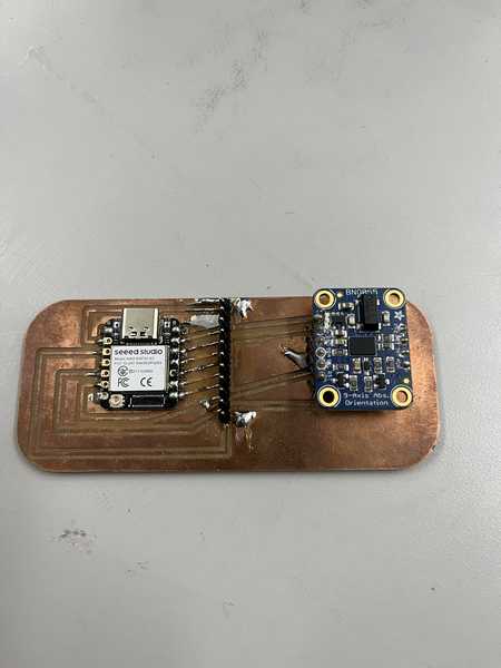
My soldered board
Making my board work
** Some of this work has been taken from my final project section
This site from Seeed helped me set up the microcontroller for the first time. The setup process was just pasting the board library into the preferances section in arduino, after that, I had to hold down the “Boot” button to put the board into bootloader mode, which I then selected the board from the drop down menu.
Code and video
#include <L298N.h>
#include <ESP32Encoder.h>

#define CLK 9 // CLK ENCODER
#define DT 8  // DT ENCODER

ESP32Encoder encoder;

const unsigned int IN1 = 44;
const unsigned int IN2 = 7;
const unsigned int EN = 3;

L298N motor(EN, IN1, IN2);

const float Kp = 1.0; // Proportional gain
const float Ki = 0.0; // Integral gain
const float Kd = 0.0; // Derivative gain

const float setpoint = 1000.0; // Target position
float error, integral = 0, derivative, last_error = 0;
float output;
bool firstIteration = true;

void setup()
{
  encoder.attachHalfQuad(DT, CLK);
  encoder.setCount(0);
  Serial.begin(115200);

  motor.setSpeed(70);
}

void loop()
{
  long newPosition = encoder.getCount() / 2;
  error = setpoint - newPosition;

  // Skip integral term update in the first iteration
  if (!firstIteration) {
    integral += error;
  }
  firstIteration = false;

  derivative = error - last_error;
  output = Kp * error + Ki * integral + Kd * derivative;

  // Limit the output to the motor speed range
  output = constrain(output, -255, 255);

  motor.setSpeed(abs(output));

  if (output > 0)
  {
    motor.backward();
  }
  else if (output < 0)
  {
    motor.forward();
  }
  else
  {
    motor.stop();
  }

  last_error = error;

  // Print debugging information
  Serial.print("Setpoint: ");
  Serial.print(setpoint);
  Serial.print(", Position: ");
  Serial.print(newPosition);
  Serial.print(", Error: ");
  Serial.print(error);
  Serial.print(", Output: ");
  Serial.println(output);

  delay(100); // Adjust as needed based on your control loop frequency
}
Controlling a single motor to steer using a PID loop
I created this code to set the motor to steer to a single position using a PID control loop. A more in depth explanation of this code is under my final project documentation.
#include <L298N.h>
#include <Adafruit_BNO055.h>
#include <utility/imumaths.h>
#include <ESP32Encoder.h>

#define CLK 9 // CLK ENCODER
#define DT 8  // DT ENCODER

ESP32Encoder encoder;
Adafruit_BNO055 bno = Adafruit_BNO055(55);

const unsigned int IN1 = 44;
const unsigned int IN2 = 7;
const unsigned int EN = 3;

L298N motor(EN, IN1, IN2);

const float Kp = 1.0; // Proportional gain
const float Ki = 0.0; // Integral gain
const float Kd = 0.0; // Derivative gain

float heading_setpoint = 0.0; // Target heading
float heading_current = 0.0;  // Current heading

float error, integral = 0, derivative, last_error = 0;
float output;

void setup()
{
  encoder.attachHalfQuad(DT, CLK);
  encoder.setCount(0);
  Serial.begin(115200);

  motor.setSpeed(70);

  // Initialize the BNO055 sensor
  if (!bno.begin())
  {
    Serial.println("Could not find a valid BNO055 sensor, check wiring!");
    while (1)
      ;
  }
  bno.setExtCrystalUse(true);
}

void loop()
{
  // Read the current heading from the BNO055 sensor
  sensors_event_t event;
  bno.getEvent(&event);
  heading_current = event.orientation.x;

  error = heading_setpoint - heading_current;

  integral += error;
  derivative = error - last_error;
  output = Kp * error + Ki * integral + Kd * derivative;

  // Limit the output to the motor speed range
  output = constrain(output, -255, 255); /// Function to scale the motor output

  motor.setSpeed(abs(output));

  if (output > 0)
  {
    motor.forward();
  }
  else if (output < 0)
  {
    motor.backward();
  }
  else
  {
    motor.stop();
  }

  last_error = error;

  // Print debugging information
  Serial.print("Setpoint: ");
  Serial.print(heading_setpoint);
  Serial.print(", Heading: ");
  Serial.print(heading_current);
  Serial.print(", Error: ");
  Serial.print(error);
  Serial.print(", Output: ");
  Serial.println(output);

  delay(100); // Adjust as needed based on your control loop frequency
}