8. Electronics Design
This week I used different tools to design a board that I may use for my final project.
Group work
This week in our group, we measured different devices under an osicloscope to measure a digital, analog, and pwm signal, and explained the differences between each. We also measured devices using a multimeter
Considerations
For this week there were 3 major considerations that I needed to make. I had to think about what inputs and outputs I would use, what microcontroller, and what design softwares.
Inputs and outputs
Up to this point, I haven’t really thought about what kind of interface I’m going to use to allow the user to interact with the wagon and make it start moving. For this week, I decided on just using a buzzer so that i’ll have some sort of feedback that I can recognize what’s happening in my code. For my input, I know that a distance sensing system is going to be very important for my project. The distance sensor that I chose is VL53L1X ToF ranging sensor. I chose this sensor because it comes in a small footprint, and has percise, long-range distance sensing. The VL53L1X sensors in our lab come on the VL531X-SATEL breakout board. This board uses an I2C connection to communicate with the sensor.
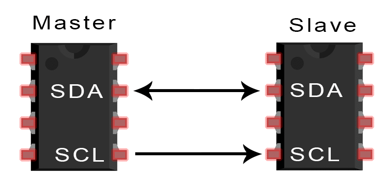
Understanding I2C
I’ve never used I2C before, so I did a little research to understand how it works. I2C uses 2 wires to allow devices to communicate with each other. The SDA line transfers data between the 2 devices Bit by bit. The SCL line provides a clock signal to syncronize the data that is sent between the 2 devices. The master device is what drives the clock line, and initates the data transfer. The slave devices provides data to the master that’s synced to the clock signal. This website helped me understand the I2C protocol
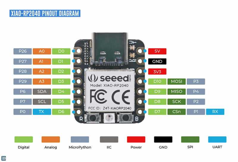
Microcontroller
For the microcontroller, I decided to use the seeed Xiao RP2040. I chose this chip because it’s based on the RP2040 chip, which I’m pretty familiar with this point, and it’s small so I don’t have to use much space on my board. For my final project, I might not be able to use this board though because there’s a very limited amount of I/O pins.
Softwares
This week, I am going to try 2 different softwares. The first software I’m going to use is Kicad. I’ve worked with Kicad before, so I’ll probably use Kicad to make my boards for milling as well as for my final project. I also wanted to try a new software though. I already have access to Fusion 360, so I decided to use the EAGLE pcb software, which is a built-in feature of Fusion 360.
KiCad
Setup
I didn’t have Kicad downloaded on my computer yet, so the first thing that I did was download Kicad from here. I went through the setup wizard and then Kicad was on my laptop. The next thing that I had to do was download a libary with the seeed studio RP2040. I found the library here and downloaded the libary onto my computer. The libary was 2 different files, one file for the schematic symbol, and one libary for the PCB footprint. I first installed the schematic footprint. I did this by going to Prefrences > Mangage Symbol Libraries. I then clicked Add existing library to table, which is a folder button at the bottom of the list. I then went to my downloads and selected open on the Module.Seeduino.Xiao file. Once I did this, I could see the libary in the list. Next, I had to download the symbol libary for the PCB design part of KICAD. First, I tried to do the same process that I did with adding my symbol libary, however, the footprings wouldn’t show up when I tried to add them. So instead, I manually added the libary by creating a new line, pasting the path that the symbols came from, and adding what type of Kicad library it is. This process worked, but I’m still not sure why I had to do this.
Schematic
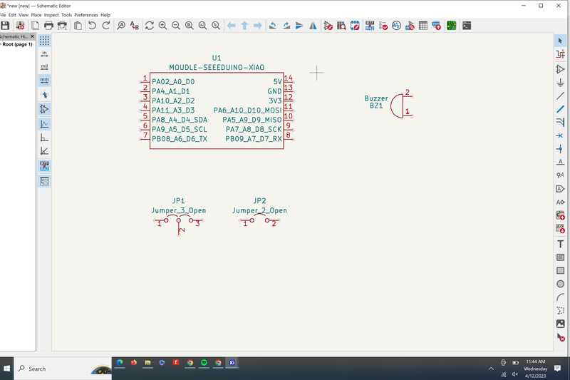
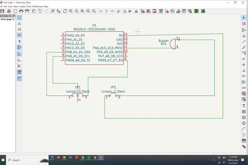
Before creating a PCB, I had to create a Schematic so that I knew what connections are where. The first thing I did was drag all the components that I knew I was going to need into my workspace.
I first added all of my parts into the workspace using the insert footprint tool on the right
I then routed the buzzer tracks and the I2C lines
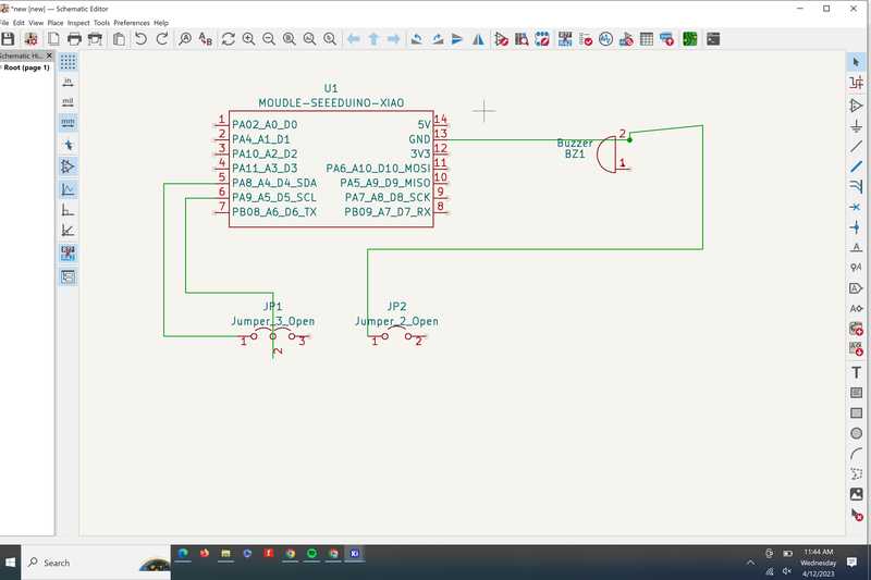
Then I added the Ground and power Lines
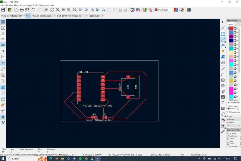
PCB
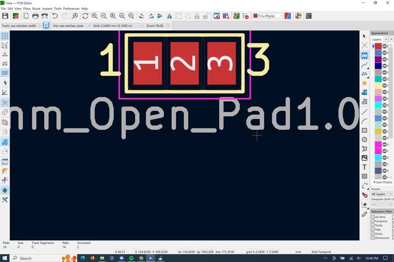
Pad footprints
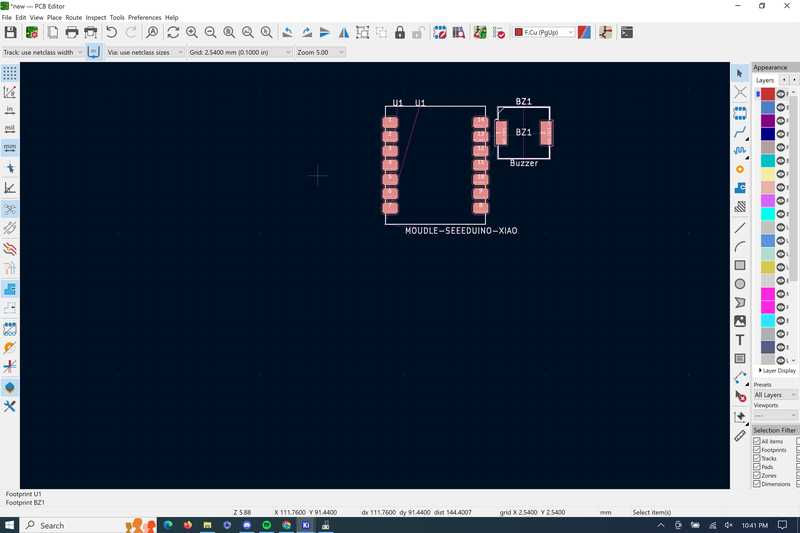
XIAO and buzzer footprints
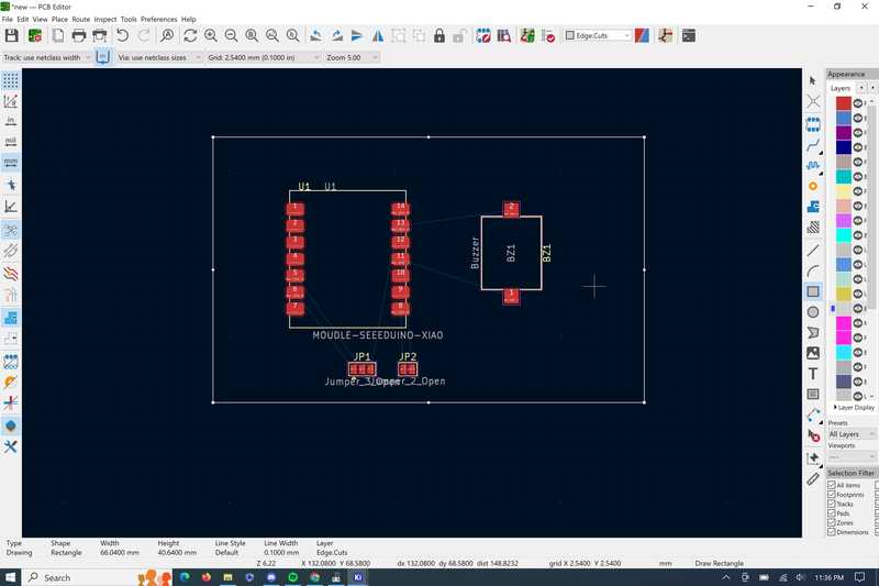
All my pieces on the design with my edge cuts.
Routing: I tried to avoid using sharp corners and using 0 ohm resistors.
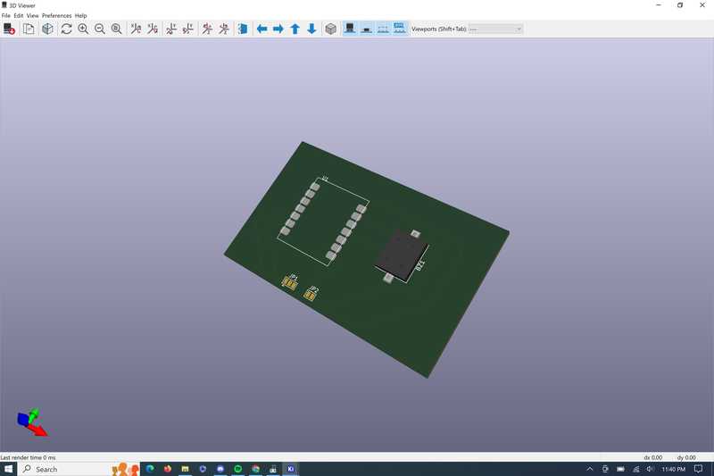
My board in the 3d viewer.
Eagle
Setup
Since the Fusion electronics design software is included with my download, all I had to do was go to File > New electronics design. Once I was in the electronics design homepage, I had to import the library for the Seeed. Fusion 360 electronics design library files include the symbol, footprint, and 3d design all in one file, so inserting the library was really simple. I downloaded the Fusion 360 library file, went to File > New electronics library > Open Library Manager and then went to import libraries and selected the file that I downloaded .
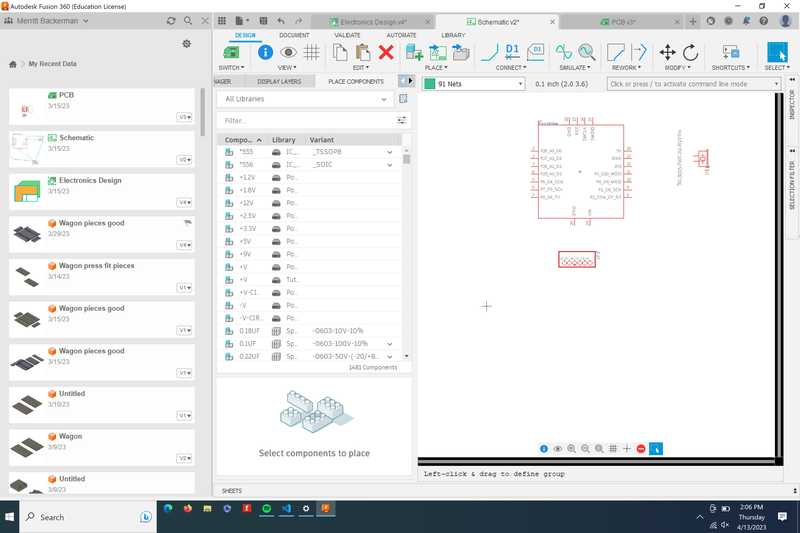
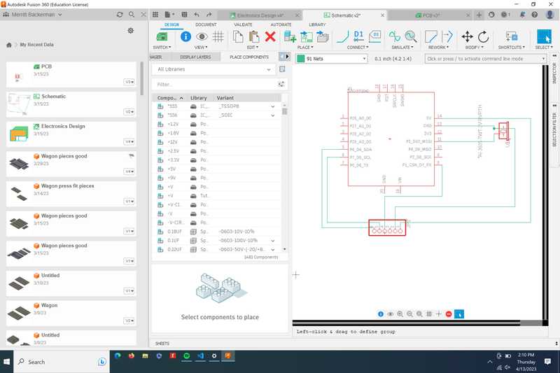
Schematic
First I put all of the pieces onto my workspace using the insert symbol tool
I then switched to the “Wires” Layer and routed the I2C wires to the left 2 headers
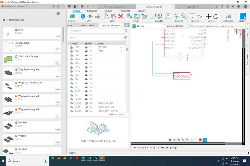
Next I connected the to leads to the buzzers

I then finished routing with the 5v and ground lines
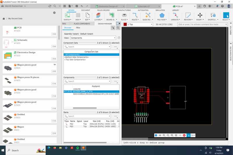
PCB design
Once I opened the PCB editor, all of the components were in my worksspace, so I moved them about the same places that my board was on kicad
Fusion 360 has an automatic routing feature, where all I had to do was click the pads that I wanted to connect, and the Fusion automatically routed the paths. 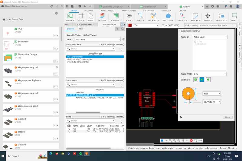
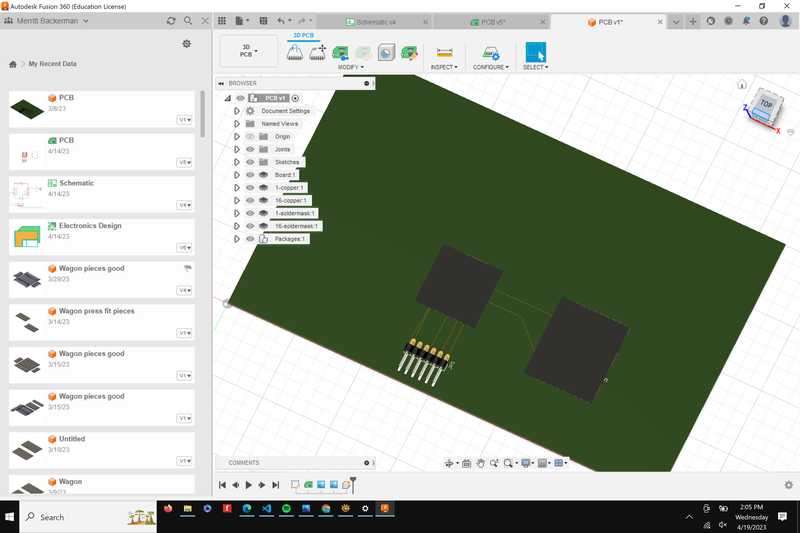
Here’s my board in Fusion’s 3d viewer. Not all of the components had 3d footprints.
Files
kicad project file, which includes my schematic and PCB
Fusion 360 Archive file which includes my schematic and PCB
Conclusion
This week I learned a lot about the electronics design process and how it differs between different softwares. I also learned a lot about proper routing and schematic techniques to make a board that can be milled.