12. Molding and Casting
This week I worked on defining my final project idea and started to getting used to the documentation process.
Group work
This week in our group, we compared the saftey data sheets for different materials,and documented the difference between the materials used in our lab.
Considerations
There were a few considerations that I had to make this week, mainly what materials to use. I also had to think about the limitations of my design with the milling machine.
Design
For the wheels, I wanted to have small bands that wrap around both sides to hold the tire in place, because of this, I won’t be able to mill it because I’d have an undercut, so, I want to 3d print the wheel design and then mold and cast. For the tire, because I’m casting soft, I can do a process called direct mold casting, where I directly cast my material into my milled out mold. To do this, I have to mill a negative of my final product.
Materials
For my final project, i’m planning on molding and casting my own wheel and tire set. This week, I want to make a smaller version of this. For the tires, I’m planning on using some sort of soft silocone material to cast the wheels in. Because we don’t have any soft casting material, I’m planning on using our soft molding material as it’s still silicone. For the wheels, I did a little research and I found that polyurethane resin applies well to the forces of wheels so that’s the material I’m planning on using.
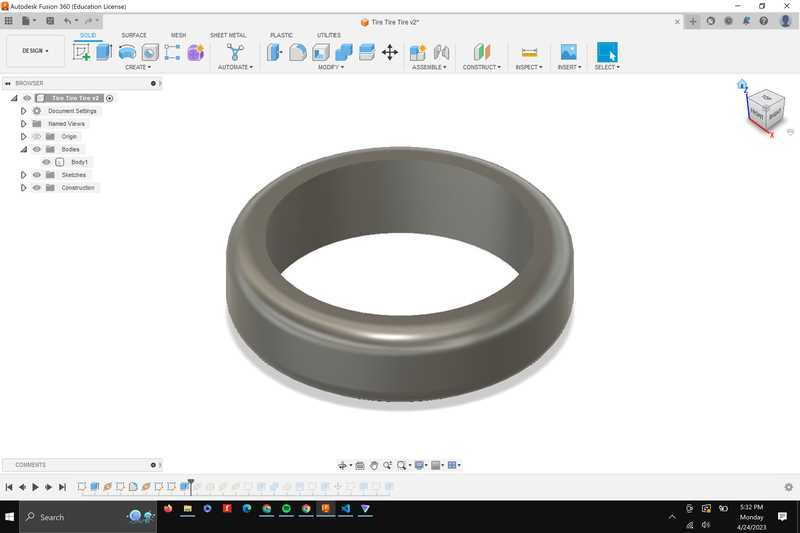
Designing the Mold for the tires
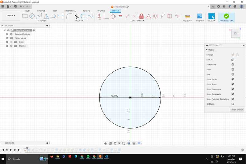
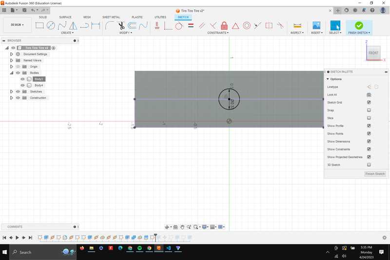
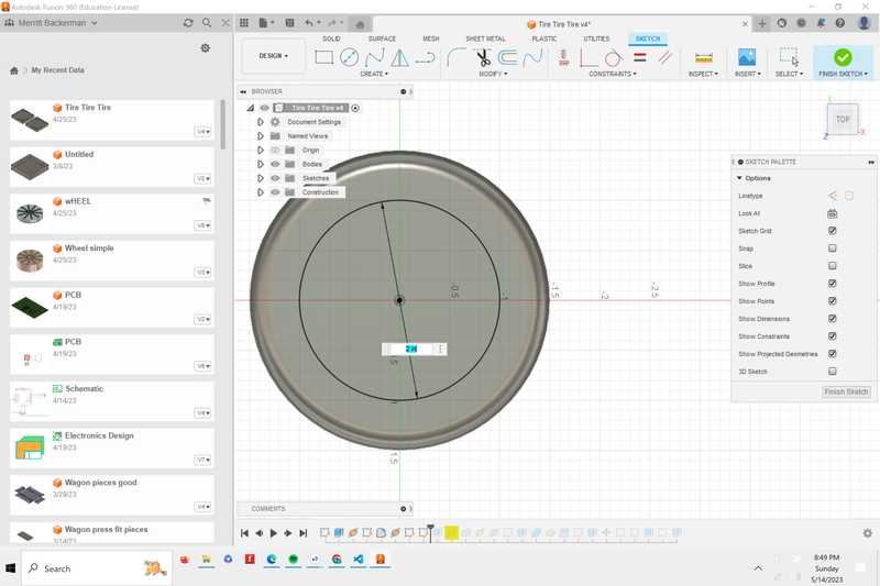
Starting with a circle for the basic shape
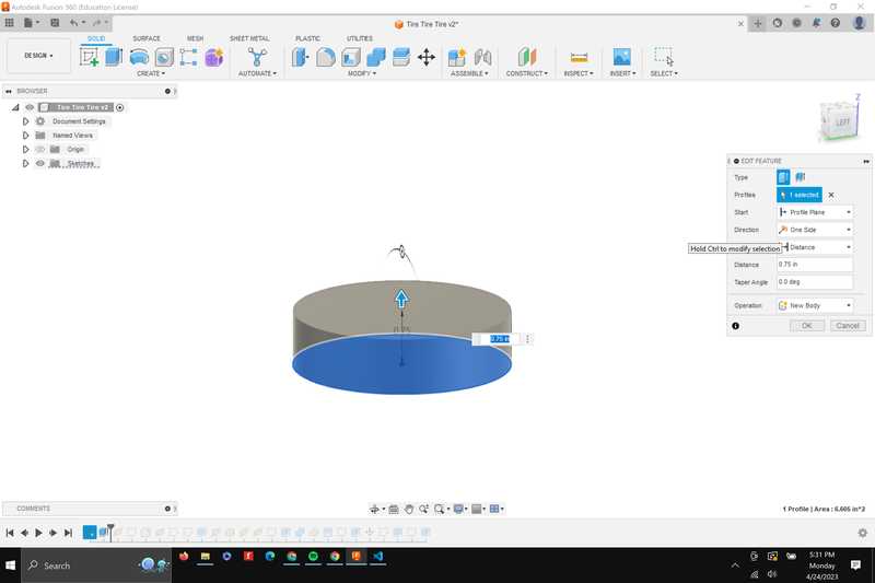
Next, I extruded the sketch to make the 3d shape of the tire
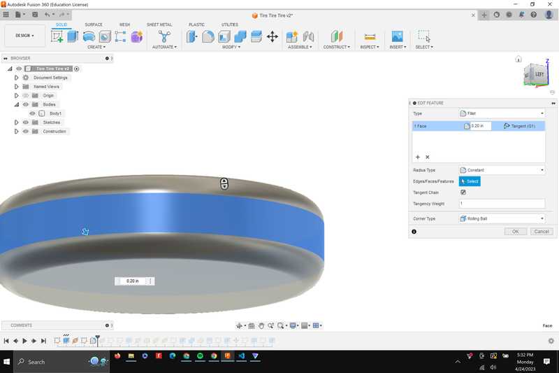
I then added a fillet on each edge to make it closer to the actual shape of a tire
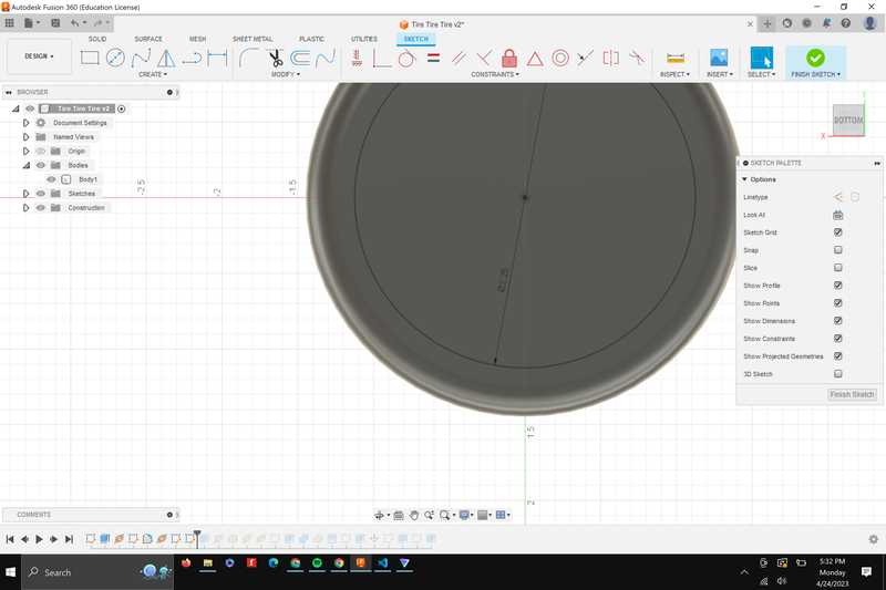
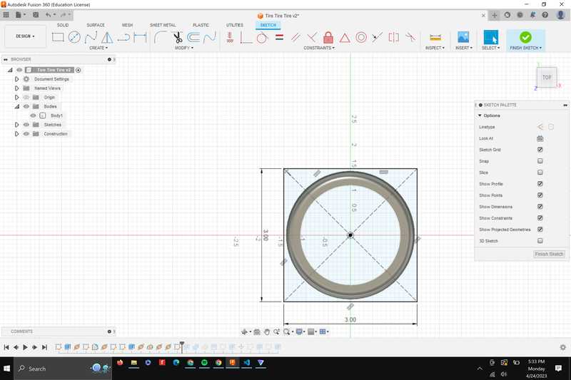
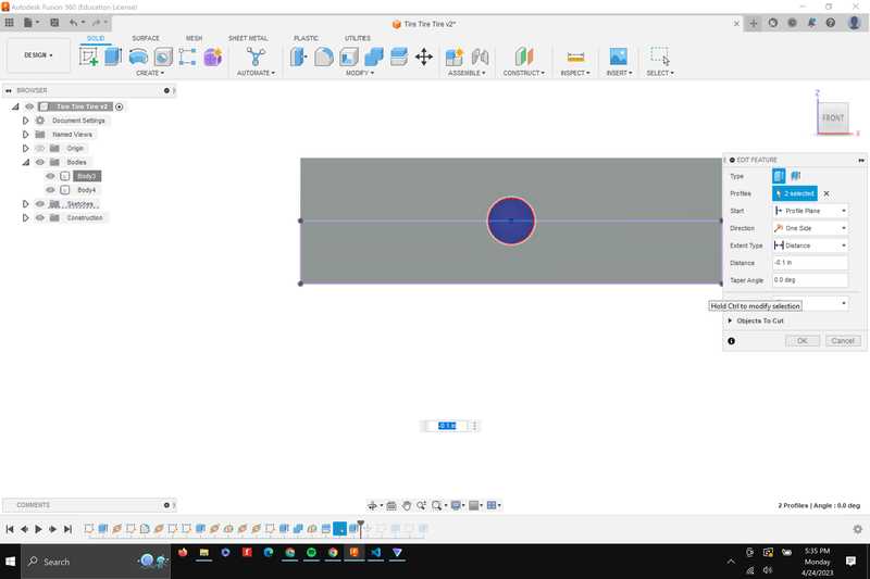
Next, I added a sketch for the central hole for the tire and extruded it to cut through the whole tire
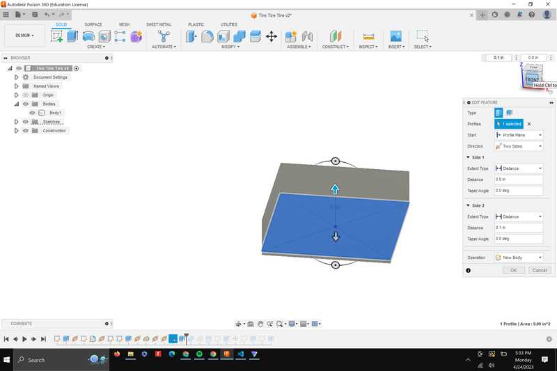
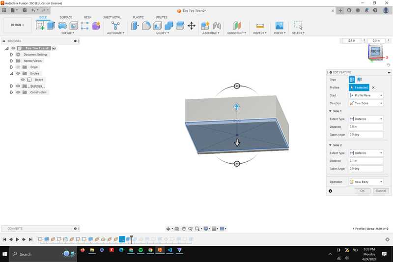
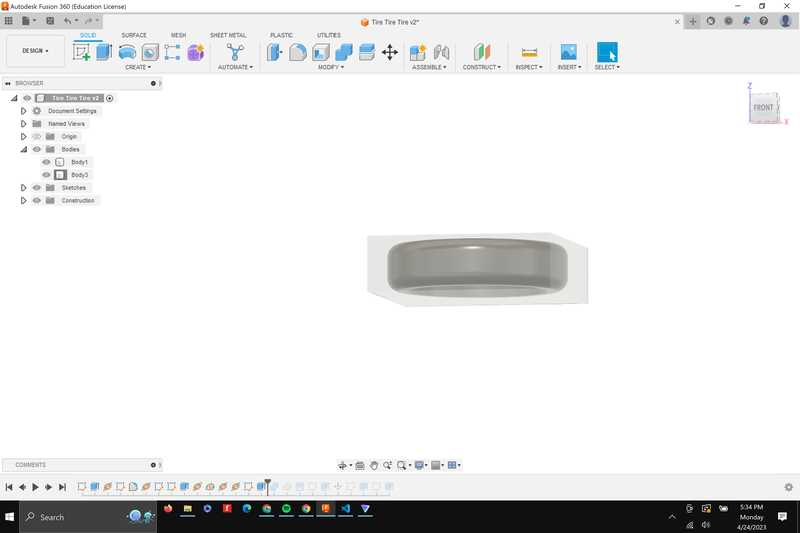
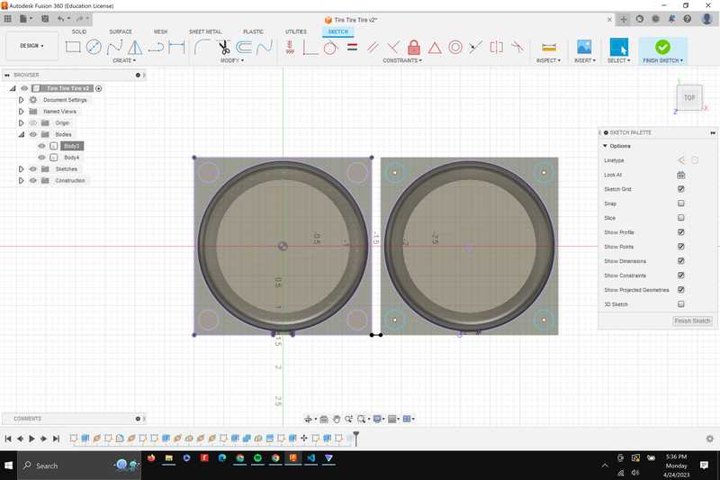
Next, I created a box that was roughly the size of the tire to be turned into the mold
I then extruded the box both ways to encase the whole tire
Here’s what the piece looked like inside of the mold with the opacity turned down
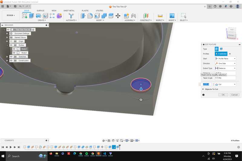
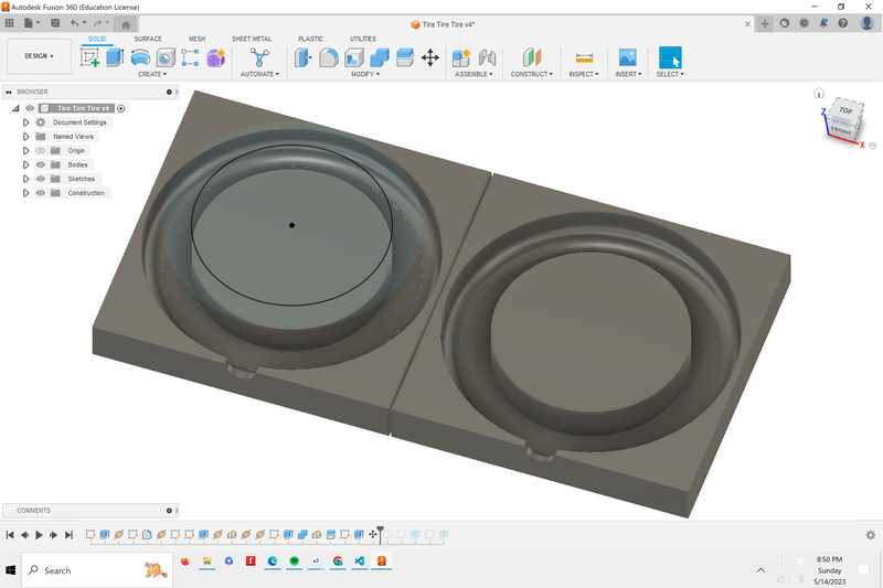
I then used the combine feature to cut the shape of the tire into the mold
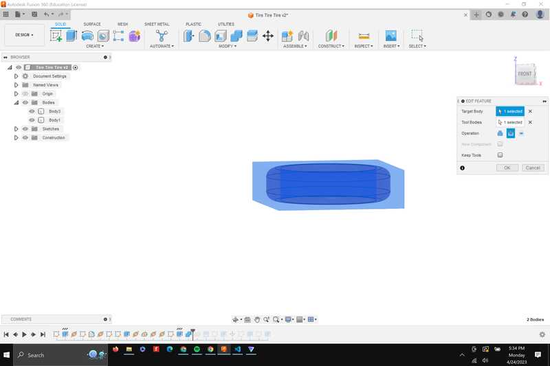
Then, I added a midplane to be used as the tool to cut my mold in 2
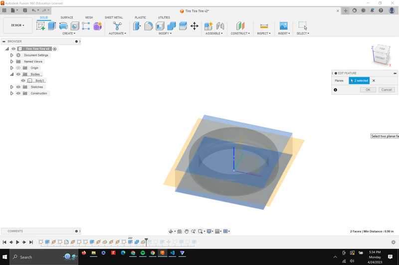
Here’s what half of the mold looks like
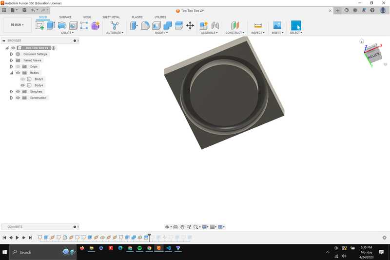
I then added a hole on the side for the material to be poured in
I then added pegs and holes that will fit the 2 pieces together
Milling
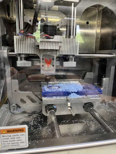
This week, I used the Bantam milling machine again. The only thing different in my workflow is that I had to measure the size of my stock with calipers instead of using the sock probing routine since wax isn’t conductive. A mistake I made was I forgot to zero out the bit the first time so it just started air cutting. However I then re zeroed the bit and cut.
Milling problems
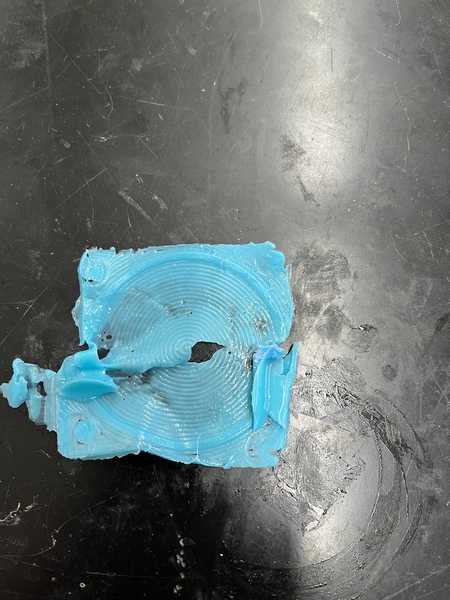
When I was getting down to one of the deeper passes for the tire body. The stock slipped off the bed. I stopped the cut and then took the stock off, retaped it, and resumed milling. When the cut finished, however, It looked nothing like what I had in my design, the cuts for the tire body were incredibly shallow.
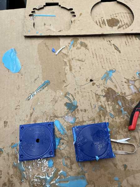
Getting a cast done
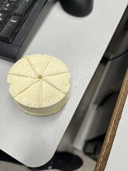
Even though my design is not at all what I expected it to be. I still just decided to cast it to get someting done for the week. The first thing I did was drill a hole in the top of one of the designs, since there was no space for material to get in through the side hole, which you can see in the picture above. Another mistake I made was that I added round holes and pegs for my mold when they should have been spheres because it was milled with a round cutting tool, so the kerf from the bit made it so the holes don’t fit. I took a chissel and scraped off what I could of the pegs, and then filed and sanded the rest down.
Material
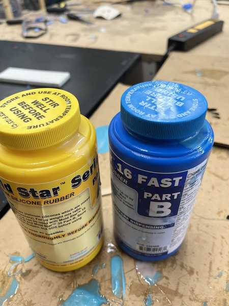
For my material, I decided to use Mold-Star part A with Mold-Star 16 fast. I decided this because of the durable silicone material as well as the fast set time because of the part B. Based on the saftey data sheet I knew that I needed gloves and goggles.
Casting
To cast, I first shook each container thoroughly. I knew that I wouldn’t be able to do a water pour test to estimate the volume needed because the volume was so low. So I just went to the crease line on the cup which is about 10ml. I rubber-banded the 2 sides of the mold together making sure that the pieces were aligned. I then poured part A and B together and mixed for a few Mins until pouring into the mold. It took a little time for the material to settle into the mold, but I was able to get it to fit.
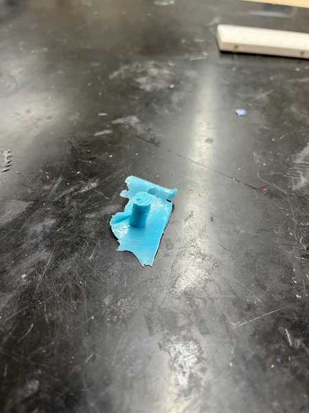
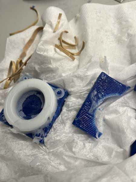
When I took the mold out, I got this stem piece from the hole that I cut away
 !
!
And here’s the “Final” result. I will be coming back and making another cast, but this is what I have for now.
Revisiting
What I did wrong
Looking back at my original toolpath, I realized that there was no problem between my design and milling, as the toolpath’s result was the same as the simulation result, which I didn’t notice the first time. The problem with my toolpath was that the the width of the tires at deeper points were less than the width of the cutting tool, so it only cleared the first holes in my design. Another mistake I made was the pegs and holes in my design. The pegs and holes made did not fit together because they were cylinders. Because of this, the holes were cut inside, making them smaller, while the pegs were cut outside of the line, so they were made larger. The last mistake I made was that I did not follow the directions of using a roughing and finishing toolpath, and instead I just had one detailed toolpath using the ball nose. This time, I’ll have one toolpath using a flat end mill that’s rougher, and one toolpath using a ball end mill that has more detail.
Redesigning- Cad
To fix these problems, I decided to start from scratch to redesign, as my design isn’t very complex. The only things that I changed from my original design are the following:
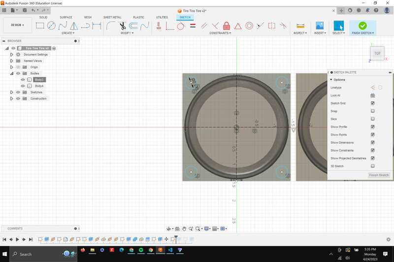
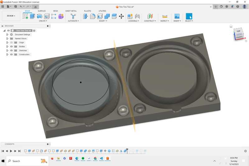
First, I changed the clearence between the inner and outside circle of the tire, so that there will be enough space that can be cut.
New clearence in 3d view
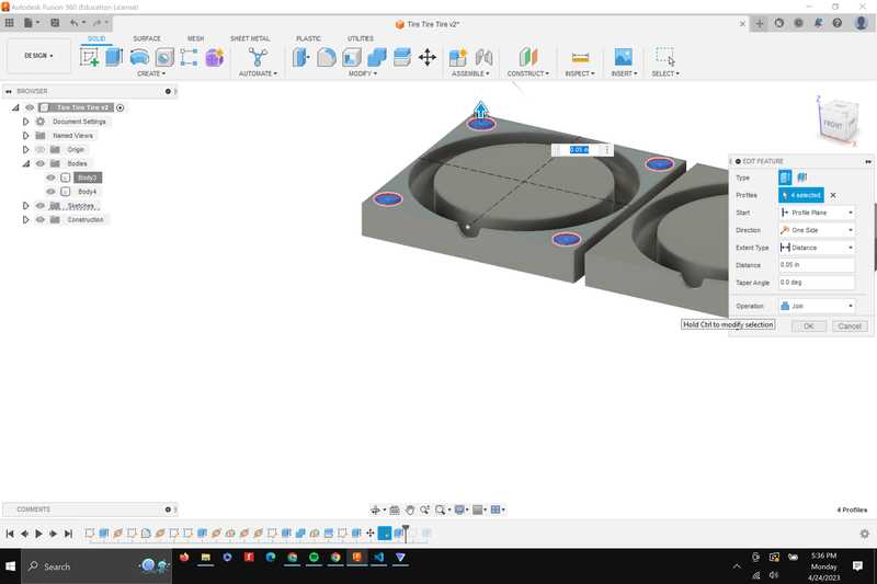
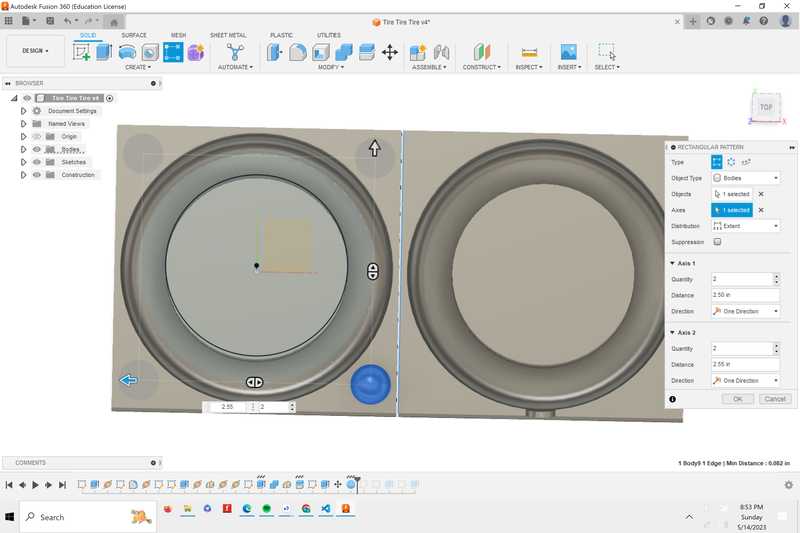
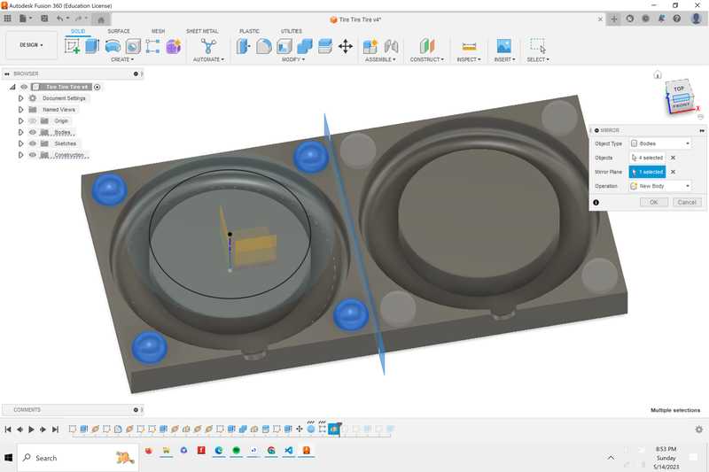
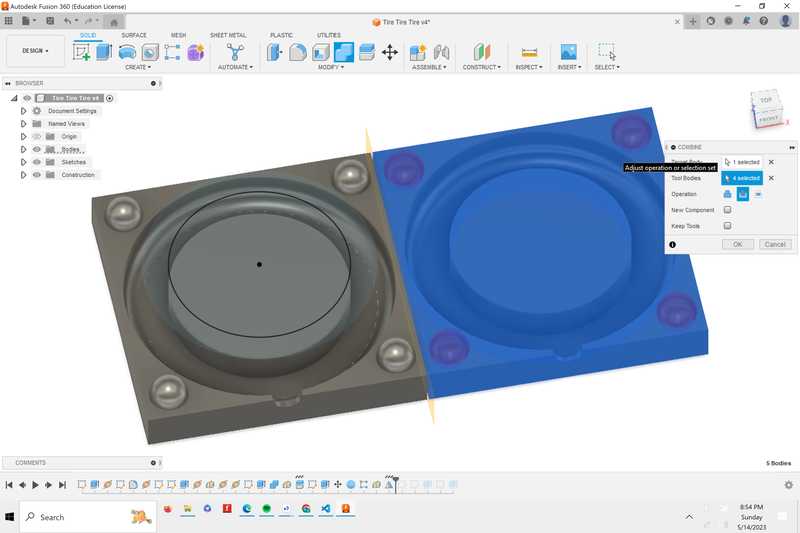
I also changed the pegs to spheres by placing one sphere and using the rectangular pattern to place them on the other corners, and then mirroring the spheres across to the eother side of the design, and then using the combine tool with the cut feature to make one side with holes.
The first sphere
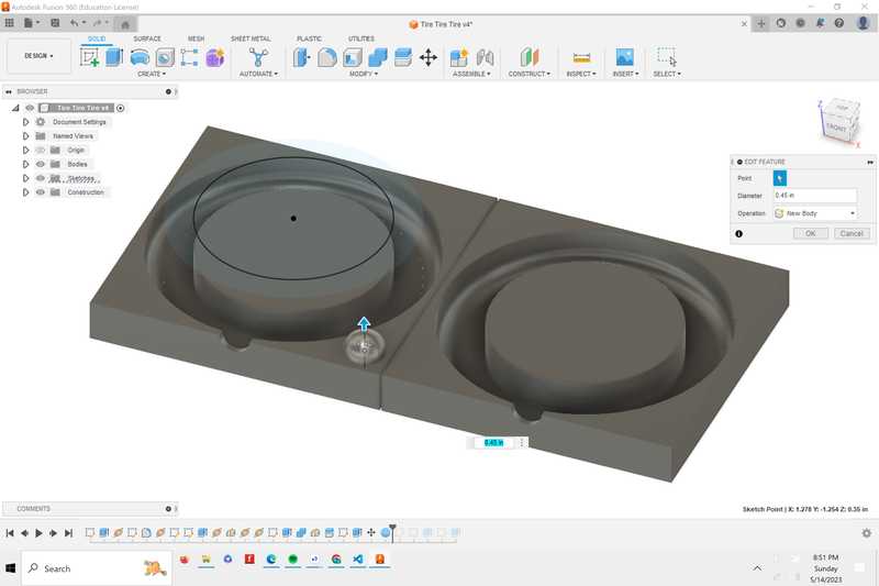
Rectangular Pattern Tool
Mirroring the spheres, I created a midplane to mirror the spheres my selecting rightmost and leftmost faces
Using the combine tool to cut the spheres into the rectangle.
The Sphere Peg and Holes Finished
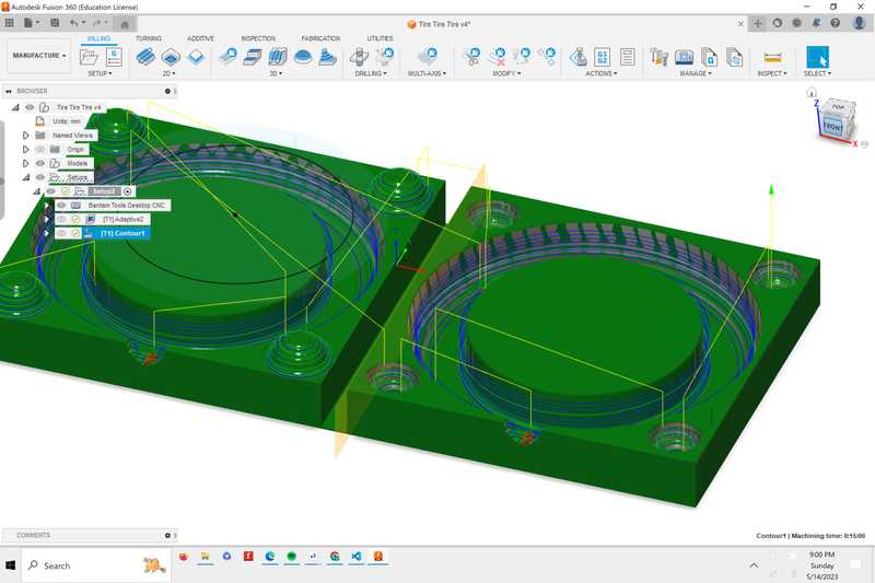
Redesigning- CAM
In my CAM, I changed my strategy by using 2 different toolpaths, a roughing pass to clear out material quickly and a smoothing pass for clearing out the more detailed parts of the piece. For the roughing pass, I’m using a 1/8 inch flat end mill because the whole end of the bit is able to clear out material. For the finishing pass, I’m using a 1/8 inch ball nose end mill because only the tip of the bit clears out material, so it’s able to get the finer details of what I’m cutting
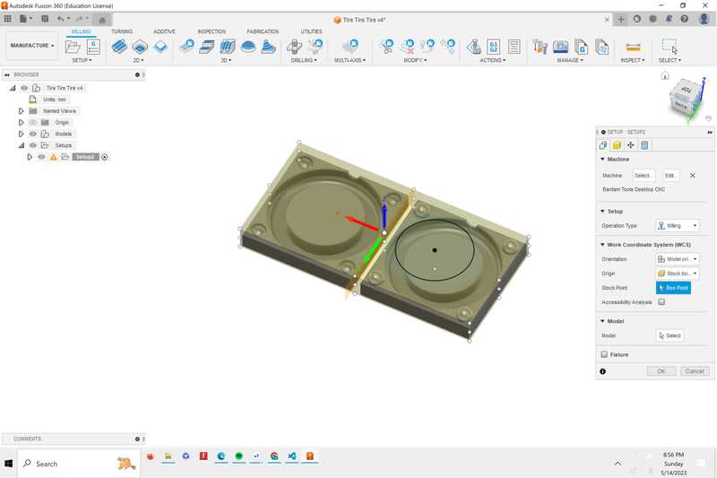
Setup: I decided to use an adaptive stock because I know I’ll be able to cut my design out of the stock pretty easily if the stock is bigger than the adaptive
Roughing Toolpass with adaptive clearing: the adaptive clearing toolpath maximizes the amount of material removed, which I could see when I simulated the toolpath.
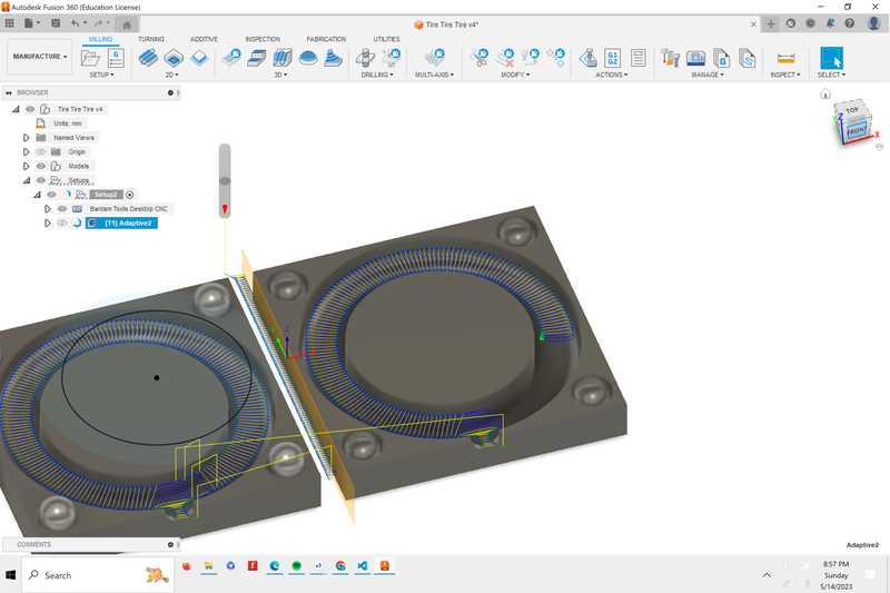
Finishing Toolpath: I chose the countour toolpath because there wasn’t enough clearence in the bottom of the tire to make a finishing path useful, as the roughing pass couldn’t step over between passes much. The countour toolpath cleans up vertical walls of the toolpath, so they’ll be smoother inside. It also will make the sphere’s smoother because it will go up each of the small walls of the incomplete sphere that will be made from the roughing toolpath.
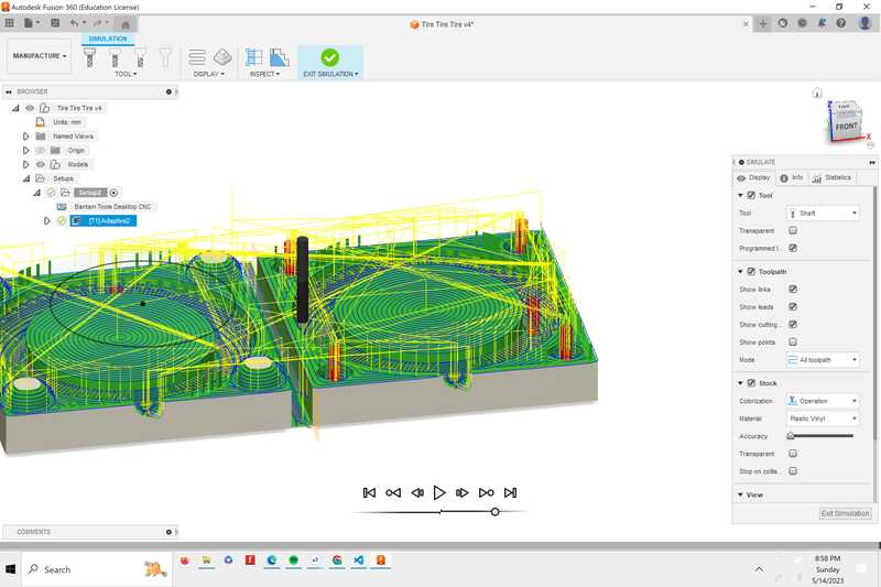
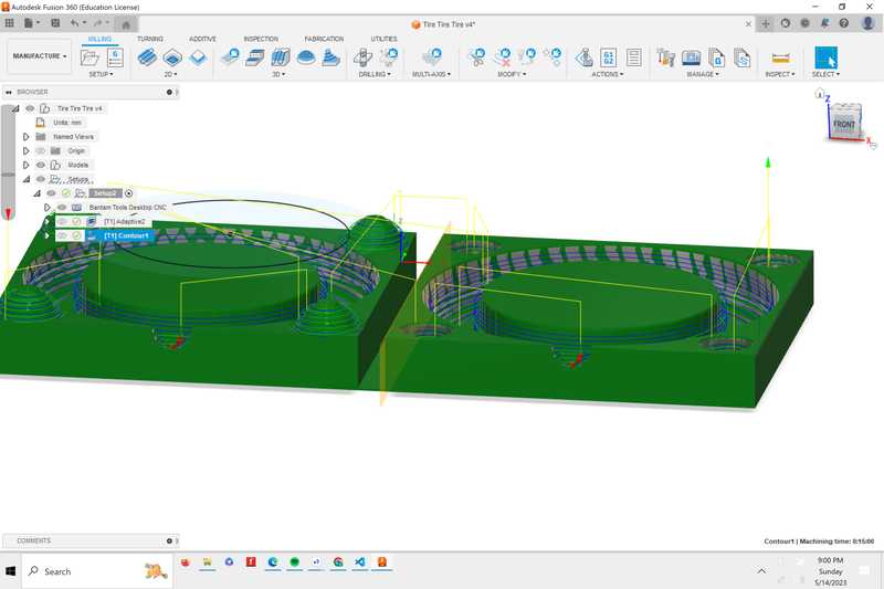
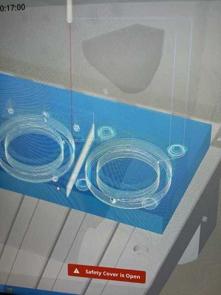
Simulating the toolpath:
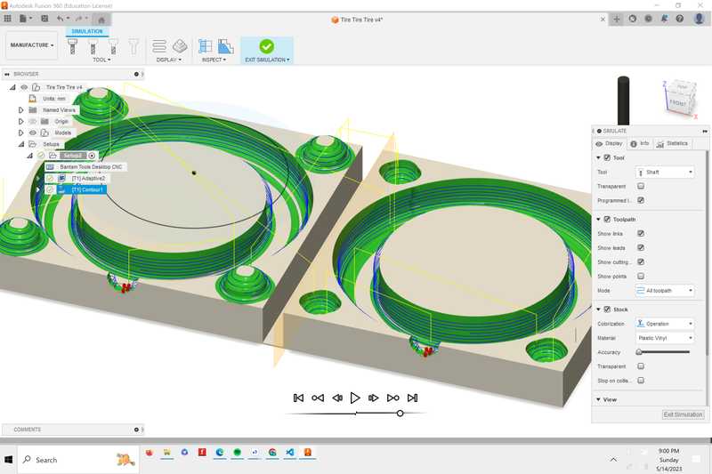
Both of my toolpaths combined:
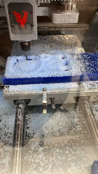
Remilling
There weren’t too many changes between milling for the first and second time, but here are some that I made and demonstrations of the differences between the roughing and finishing passes.
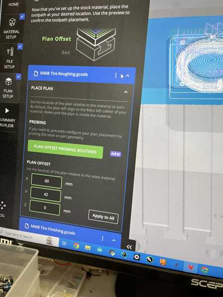
I offset the stock so that it was placed above the bracket, since the bracket was too big for the stock
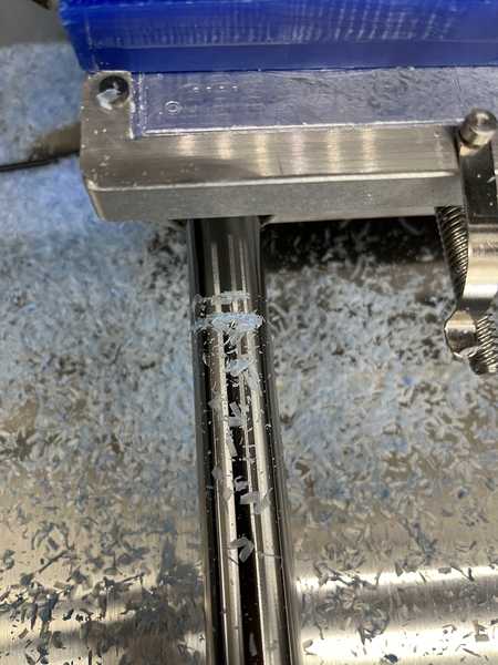
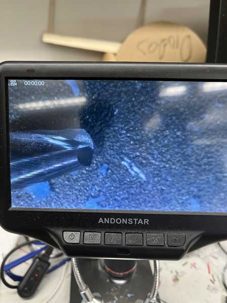
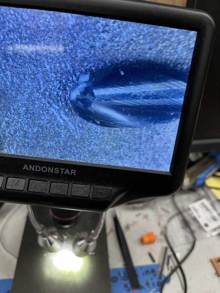
The flat end mill under a microscope, the whole end of the mill cuts the material
The flat end created large chips, and went through layers quickly
After the roughing pass: the inner walls still had some ridges
Finishing pass: the finishing pass ramped up the walls to smooth them
The ball nose end mill which comes to a point as it’s the only part of the tool that removes material.
The finishing toolpath removed finer pieces of material since less is removed from every revolution of the bit.
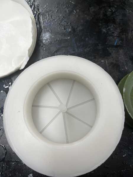
My finished product. When I removed the excess material, a corner broke off of one side of the mold, but I was able to heatgun it back together well enough that I could cast with it
Casting again
For the tires, I used the same materials as I did in my first pour, and I followed the same steps and saftey procedures as I did last time. The piece that came off when I removed the mold from the stock also had a piece on the side that came off, so I hot glued it together.
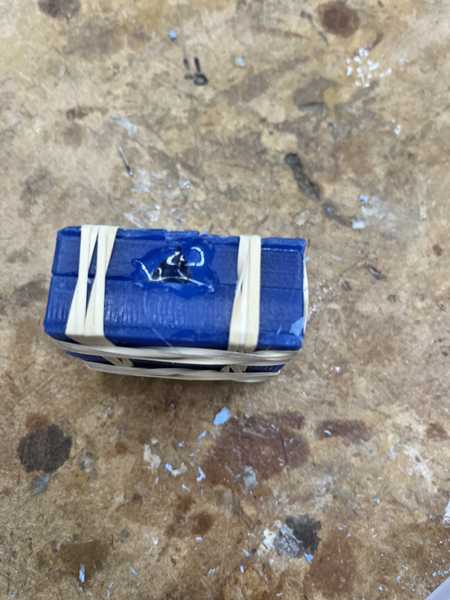
The pieces together after letting them dry, there was some leaking out of the sides but I had a rubber band around the seam to try and provent some of that.
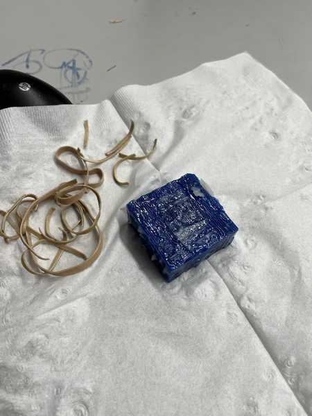
My cast after the 2 halves of the mold being taken apart, a piece of the mold did snap when I took it out, but luckily the cast looked like it went pretty well.
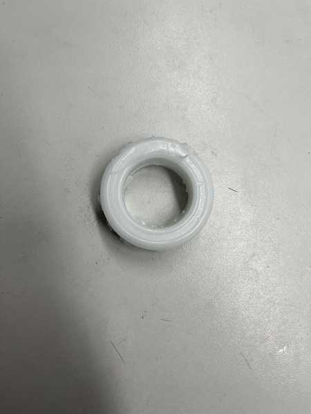
After a little post processing of cutting out excess parts, this is what the tire looked like
Casting the wheel
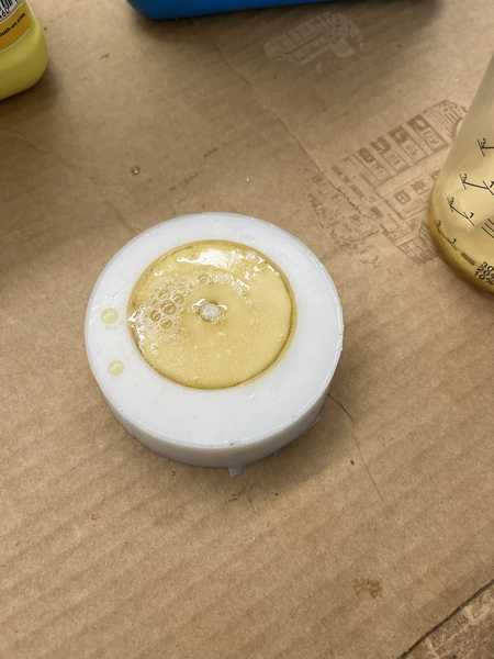
To create the wheel, I first made a mold of the wheel using the same silicone as the tire, and then cast in that mold with task 8 urethane resin. I hot glued the wheel to the bottom of the popcorn bucket.
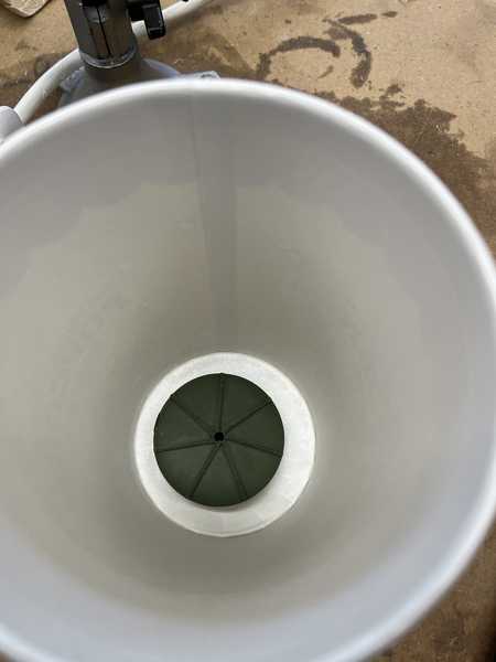
I then filled the popcorn bucket with enough silicone to to fill it up to the top of the wheel.
Here’s what it ended up looking like
I then casted using Task 8 Urethane Resin, by Smooth-On, which follows the same PPE rules as mold star.
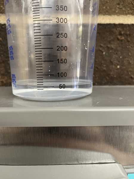
I filled the mold with water first to estimate the amount of resin that I’ll need, which ended up being around 50 ml.
I then combined equal amounts of part A and part B by volume, and stirring.
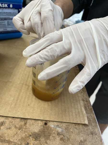
The cast turned from dark brown to light, and hardened within about 15 mins.
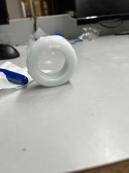
Taking the cast out of the mold, I got this as a final product
Files
My tire as a .3mf file: file
My wheel as a .3mffile
NOTE: these Gcode files are configured for Bantam Tools/Othermill machines only
The roughing pass gcode file
Finishing pass Gcode file
Conclusion
Besides just molding and casting, I learned a lot about CAM tools and the milling process. I learned about using a roughing toolpath and a smoothing toolpath, and what bits to use for each one. For the molding and casting process, I learned about saftey processes when working with different materials, calculating how much material I would need to make a cast, and how to perform the casting process.