7. Computer controlled machining
This week I used CAD and CAM tools with our labs CNC router to create a large design for my final project. I worked with a group to characterize the milling machines at our lab.
Group work
This week I performed a runout test on the desktop shopbot CNC machine, which can be found here
What I’m Making
This week, I’m going to make the bed of the wagon for my final project. I plan on making it press-fit, but if the press-fit design isn’t strong enough, I may use 90 degree brackets to connect pieces together better. I also didn’t want to just use a normal finger joint, so I looked around at some designs and I ended up finding this forum which documented a blind finger joint. This joint can only be seen from the inside, which I think would add a nice touch to the design. Before hopping into CAD, I made a quick sketch of what I wanted my design to look like. I didn’t want to just do a plain open box for the bed, so I sketched out this design.
Designing
Designing- Software Considerations
This week, I am going to use 2 softwares. To make my design, I’m going to continue to use Fusion 360. However, for my CAM software, which is what turns my design into gcode for the router, I’m going to use vetric’s aspire software. I chose this because our lab’s main router is made by shopbot, which is really well supported with aspire.
Designing- CAD
Designing my piece in CAD went pretty smoothly, as the only part on the original design I didn’t know how to do was the dogbone inside corners and the fillited inside corners, which could be done much more easily in my CAM software. Here’s the steps I took to make my design:
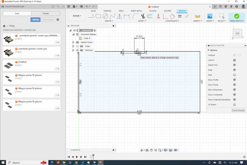
I started off by creating a rectangle with a tab attatched to the middle of the rectangle using the midpoint constraint
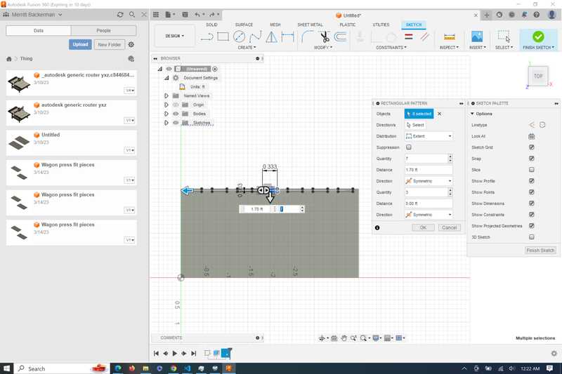
I then used the rectangular pattern tool to repeat the rectangles across this edge. I made sure that the pattern was symetrical, and then used the handle until it was a place I liked.
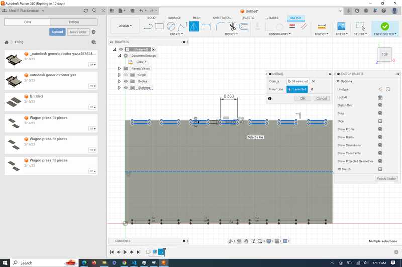
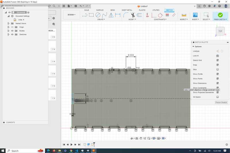
I then created a construction line across the center of the rectangle and reflected the tabs across this line
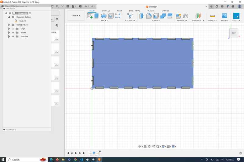
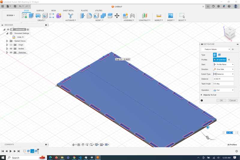
After I finished the sketch, I extruded the rectangles down -.5 inches, which is 2/3 of my material thickness
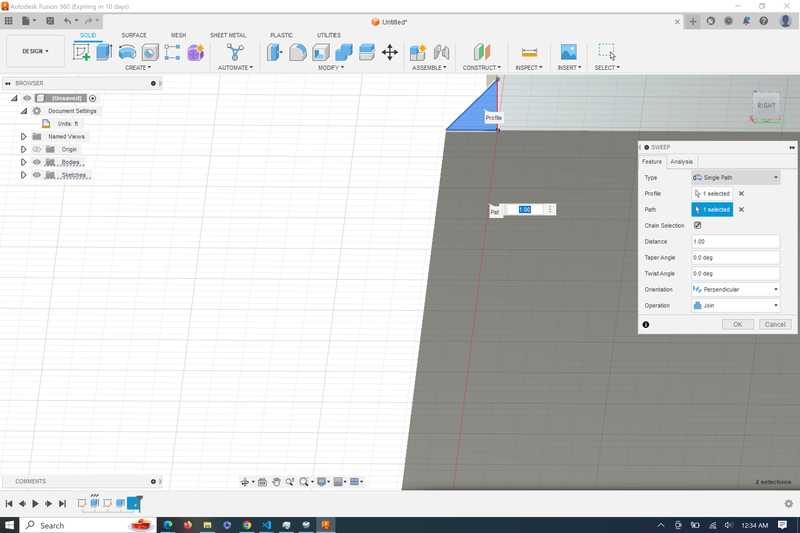
Next, I had to make the miters that run across the edges of the design. I started by creating a sketch attatched to the corner. I only knew the length of the vertical line which was going to be .25in, but I also knew that it was going to be a 45 degree right angle triangle, so I could solve for the lengths of all the lines (thanks, geometry). Once I had created the triangle, I used the ‘sweep’ function. The sweep tool extrudes a closed sketch profile across a path, so I just chose the lines of the rectangle, and the miter looked like this.
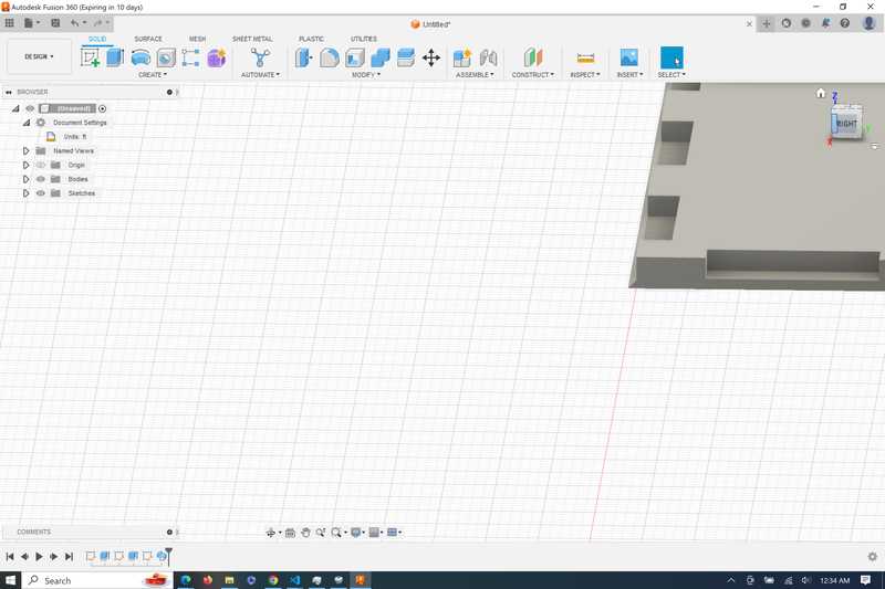
I then repeated these steps for the side pieces, with the tabs being the inverse of the ones on the base piece.
Designing- Redesign for this week
After I finished these pieces, I realized that the pieces were going to take a long time to mill, and will require multiple tool changes. Because I dont have the time to mill out the pieces, I instead decided to mill the simple tabbed box part of the design. To do this, I created a new sketch, projected the faces of the box, and then saved the sketch as a DXF file.
Desigining- CAM
The next thing I did was take my designs into Aspire. I did this by opening aspire, creating a new file, and importing the .DXF file. I then did some pre-toolpath changes.
I used the nesting tool to place all of my pieces correctly onto the cut bed with a clearence that was greater than the diameter of the cutting tool.
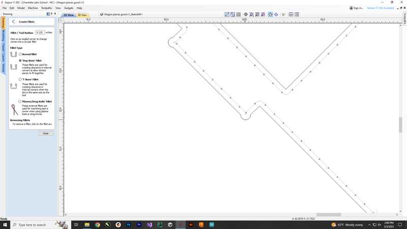
I created dogbone fillets on each of the corners so that the pieces fit together correctly, I needed a dogbone fillet because a round cutting tool can’t create a perfect corner, and the dogbone fillet accounts for that

Toolpath
Now I had to create my toolpath. I selected all of the pieces that on my workspace, and then I selected the create new toolpath action.
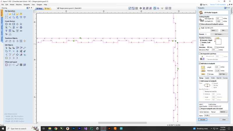
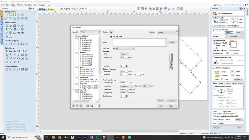
Next I selected the 1/4 inch flat end mill
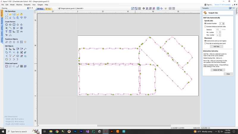
I then added tabs to my toolpath, tabs are small pieces that are not milled all the way through in order to keep the piece securly on the cuting bed.
Next I previewed my toolpath in 3d to make sure that the tabs were placed correctly and that the toolpath cut where I wanted it to.
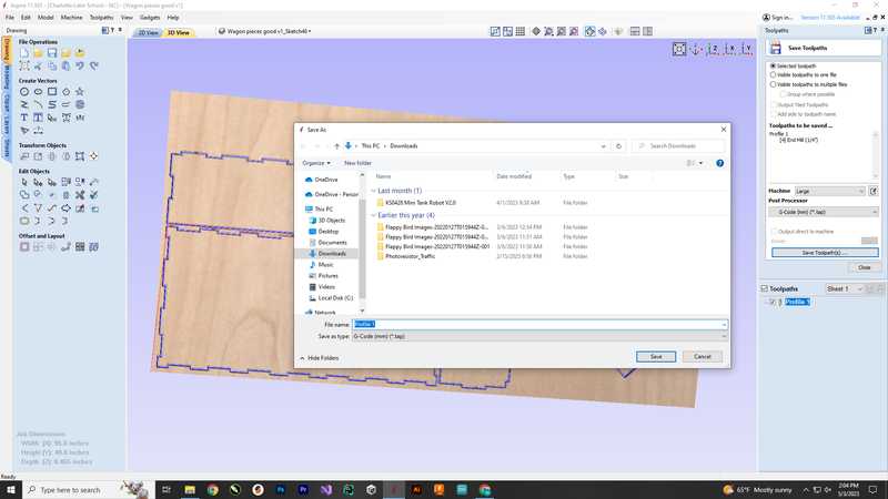
Once I verified the toolpath was correct, I saved it to my files to the export to the shopbot computer.
Shoptbot Software and milling
To mill my piece I followed this workflow made by our lab:
Shopbot Cutting using Aspire/ VCarve Toolpath
Shopbot Machine Put on eye and ear protection Close the doors Check to see that the machine has been warmed up Check to see bit is not loose Measure thickness of material that you plan to cut. Attach material to the table using screws Raise Z AXIS 4 inches using the MZ 4 command Use the proximity switch to set Calibrate. (C3 keyboard command) Calibrate Z AXIS on the table. (C2 keyboard command) Raise Z AXIS 4 inches using the MZ 4 command Set new X and Y Origins for your design Raise the Z-axis so the bit won’t drag on the table Using keyboard move to the appropriate X and Y location. (M2 X,Y) Using keyboard to zero the appropriate X and Y Location. (Z2) You set origin. Select Cut Start up Aspire and VCarve software Open your file Select objects you wish to cut Select Toolpath Pin Toolpath Click on material setup Check Z - zero is on the bed, NOT the board Enter the thickness of the material * Model position material should be the same thickness of the material. Click OK. Go to TOOL PATH OPERATIONS Select 2D Profile Toolpath Under cutting depth, select the cut depth of the material (CLS tools). Select the proper tool -CLS down bit ¼ Click add tabs and add tabs Hit CALCULATE. Preview toolpath Click on CLOSE Select SAVE TOOL PATH and save the file in a shopbot format
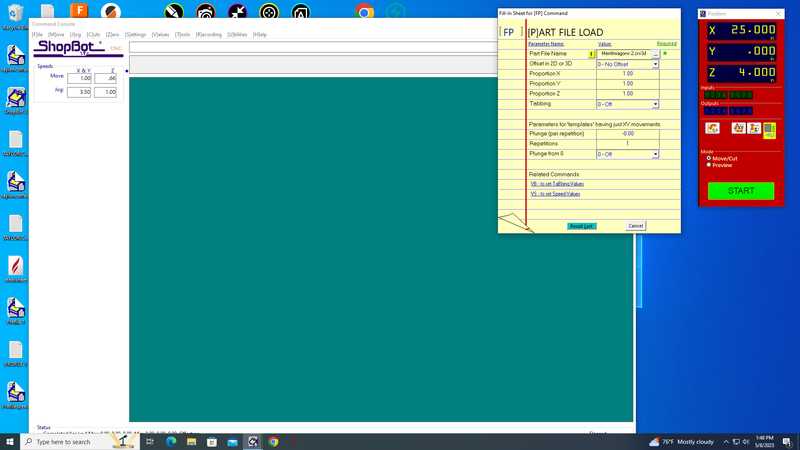
Start ShopBot Command Console Conduct air cut Select FILE-LOAD Load the appropriate file Select 1 3-D offset Press ENTER Turn on the spindle by pressing the big GREEN Button You should hear a “SOUND” of the spindle now turning Press ok After checking that everything is good; press space bar Select quit Return to origin (M2 0,0) Perform cut Select FILE-LOAD Load the appropriate file Select no offset rather than 1 3-D offset Press enter Turn on the spindle by pressing the GREEN Button You should hear a “SOUND” Turn on the vacuum Press enter again to start cut Cut is done Turn off vacuum (which is so loud you shouldn’t forget) Clean up after yourself.
Shopbot Command Console Screenshots
Jogging The Z Axis Up

Jog Commands
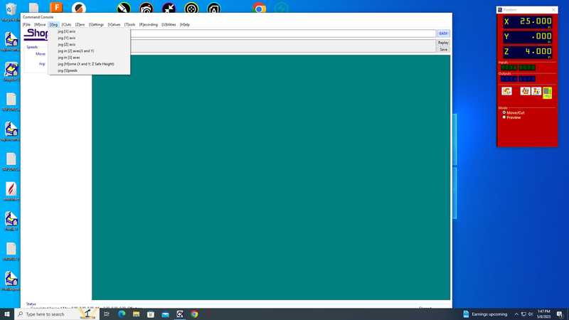
2 Axis Jog Command

Settings For Air Cut, 3d Offset

Actual Cut, No Offset
Milling Screenshots
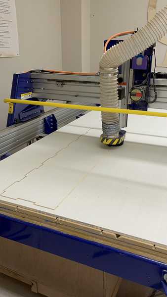
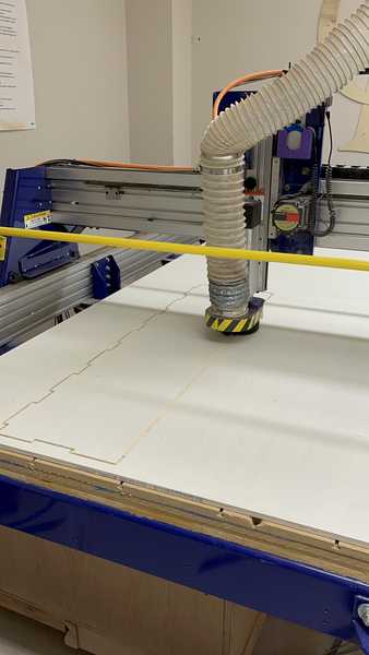
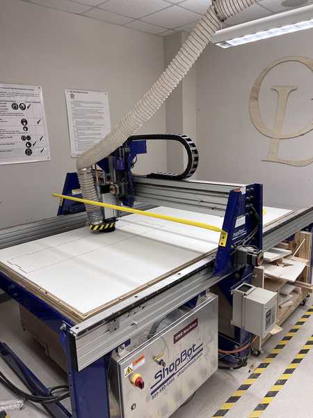
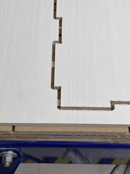
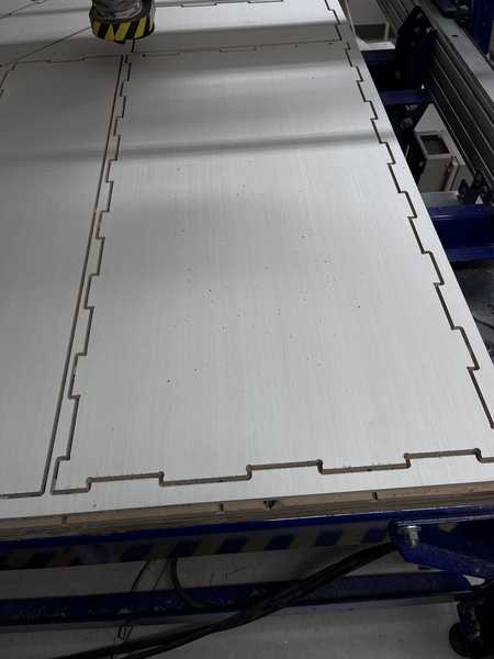
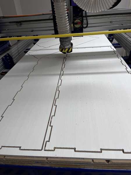
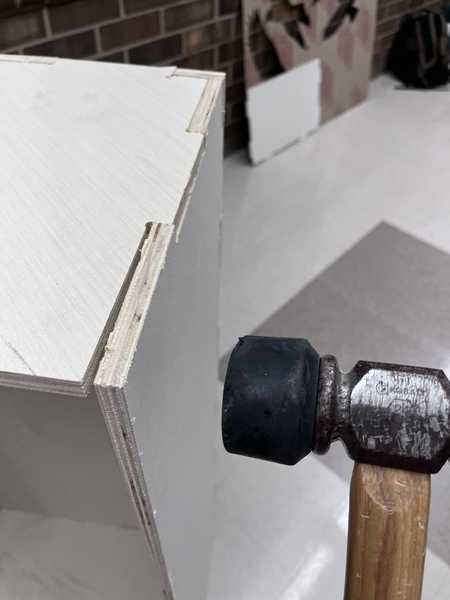
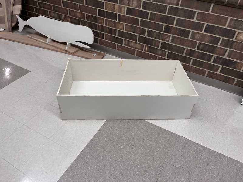
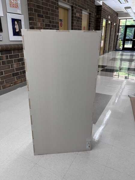
Putting my pieces together
I did a couple of test fits with individual pieces and the tabs seemed to fit really well. To put my pieces together, I started by putting all of the walls of the wagon together, some of the pieces took some gentle taps with a rubber mallet to fit all the way in. Next, I oriented the side pieces with the tabs facing up, and put the base piece on top, and hammered all of the slots in.
Conclusion
This week I learned a lot about using our milling machines, as I had only used them one time before this week. I learned about designing pieces so that they can be milled, such as undercuts and 90 degree corners.
File Download
Cad File: