11. Inputs
This week I explored different inputs and milled a board using a sensor that I plan to use during my final project. I also worked in a group to explore different inputs under an osciloscope.
Group work
In our group, we explored what different sensors looked like under an ocsilloscope. I worked with another student to explore how I2C signals work, and also decoded them under an osciloscope. The work can be found here.
Considerations
This week I only want to focus on one input, I decided that I wanted to try and get more consistent results using the VL53L1X on a milled board. I also want to try and get some kind of basic imaging working with the sensor, where I can detect different shapes. I will continue to use the board that I made in electronics production week, but I remilled it.
New Board And Testing
With my remilled board, the first thing I did was just make sure I could get a simple output working. We didn’t have any active buzzers left in our lab, which I learned that I needed from last week. So instead, I found a vibration motor. I uploaded the Arduino IDE’s built in blink code, and changed the pin to the pin the motor was connected to, and it worked
Using the time of flight sensor
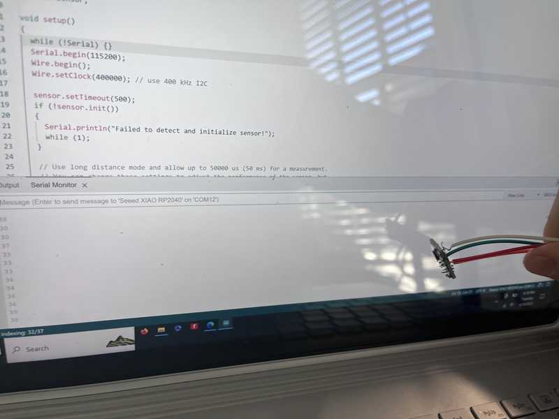
Next, I wanted to start using the Time of Flight sensor to get distance inputs. the first thing I did was install the VL53L1X library from Pololu. Then, I did the wiring. The wiring for the sensor was simple it was SDA->SDA, SCL->SCL, 5v->VIN, and GND->GND. Then, I took the simplest example code which was as follows:
/*
This example shows how to take simple range measurements with the VL53L1X. The
range readings are in units of mm.
*/

#include <Wire.h>
#include <VL53L1X.h>

VL53L1X sensor;

void setup()
{
  while (!Serial) {}
  Serial.begin(115200);
  Wire.begin();
  Wire.setClock(400000); // use 400 kHz I2C

  sensor.setTimeout(500);
  if (!sensor.init())
  {
    Serial.println("Failed to detect and initialize sensor!");
    while (1);
  }

  // Use long distance mode and allow up to 50000 us (50 ms) for a measurement.
  // You can change these settings to adjust the performance of the sensor, but
  // the minimum timing budget is 20 ms for short distance mode and 33 ms for
  // medium and long distance modes. See the VL53L1X datasheet for more
  // information on range and timing limits.
  sensor.setDistanceMode(VL53L1X::Long);
  sensor.setMeasurementTimingBudget(50000);

  // Start continuous readings at a rate of one measurement every 50 ms (the
  // inter-measurement period). This period should be at least as long as the
  // timing budget.
  sensor.startContinuous(50);
}

void loop()
{
  Serial.print(sensor.read());
  if (sensor.timeoutOccurred()) { Serial.print(" TIMEOUT"); }

  Serial.println();
}
The code then worked. The video is hard to see but at first I had the sensor pointed at the ceiling, giving me numbers in the 4000’s. Then, when pointed close to the laptop screen, the numbers drop down to the 30’s.
Next, I wanted to see if it was possible to combine multiple readings together to create some kind of depth map. I found this code online that made a web app and used multiple readings from the VL53l1X to create a 4x4 grid. I uploaded the .Ino sketch and in serial monitor I was able to get the multiple readings. However, when I opened the web app, I was getting a couple of errors. The initial errors I had were because I didn’t set the COM port and baud rate to the correct values. However, even after I set those, I still was getting error messages. I then tried to use ChatGPT to troubleshoot the coding. I was then able to get the response “The chrome.serial API is a deprecated API that was used in older versions of Google Chrome as an extension API for serial communication. However, starting from Chrome version 89, the chrome.serial API has been removed and is no longer supported. Therefore, it is recommended to transition to the standard navigator.serial API for serial communication in modern browsers.
If you still need to use the chrome.serial API for some reason, you would need to use an older version of Chrome that supports the deprecated API (prior to version 89) and also develop a Chrome extension with the appropriate permissions to access the serial ports. However, this approach is not recommended as it relies on outdated technology that is no longer maintained and may have security risks.
It is strongly recommended to update your code to use the standard navigator.serial API, as shown in the updated code in my previous response. This will ensure that your code is compatible with modern browsers and follows current web standards”
Because of this serial version being outdated, it would be difficult to make this bump map to work, which has made me rethink the use of sensors in this project.
For my final project, I’m realizing that I have 2 options for using the time of flight sensors. The first option is using multiple of the vl53l1x to create an array of sensors, which would be able to read from multiple “zones”. The 2nd option that I have is using the VL53L1, which is an advanced version of the VL53L1X, which is able to read distances in an 8x8 array.
Using the orientation sensor
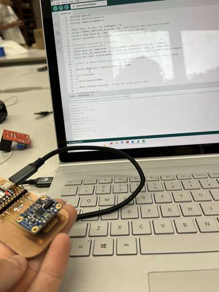
The second sensor that will be important to my project is an orientation sensor. For this, I decided to use the Adafruit BNO055. This sensor combines accelerometer, gyroscope, and magnetometer data to create a 3d orientation. This will be helpful for my project because I will be able to calculate the exact position of the wagon in terms of orientation and acceleration. I can also use the accelerometer to find the distance traveled. To start using the orientation sensor I installed the Adafruit BNO055, and then first ran the example code:
#include <Wire.h>
#include <Adafruit_Sensor.h>
#include <Adafruit_BNO055.h>

double xPos = 0, yPos = 0, headingVel = 0;
uint16_t BNO055_SAMPLERATE_DELAY_MS = 10; //how often to read data from the board
uint16_t PRINT_DELAY_MS = 500; // how often to print the data
uint16_t printCount = 0; //counter to avoid printing every 10MS sample

//velocity = accel*dt (dt in seconds)
//position = 0.5*accel*dt^2
double ACCEL_VEL_TRANSITION =  (double)(BNO055_SAMPLERATE_DELAY_MS) / 1000.0;
double ACCEL_POS_TRANSITION = 0.5 * ACCEL_VEL_TRANSITION * ACCEL_VEL_TRANSITION;
double DEG_2_RAD = 0.01745329251; //trig functions require radians, BNO055 outputs degrees

// Check I2C device address and correct line below (by default address is 0x29 or 0x28)
//                                   id, address
Adafruit_BNO055 bno = Adafruit_BNO055(55, 0x28);

void setup(void)
{
  Serial.begin(115200);

  while (!Serial) delay(10);  // wait for serial port to open!

  if (!bno.begin())
  {
    Serial.print("No BNO055 detected");
    while (1);
  }


  delay(1000);
}

void loop(void)
{
  //
  unsigned long tStart = micros();
  sensors_event_t orientationData , linearAccelData;
  bno.getEvent(&orientationData, Adafruit_BNO055::VECTOR_EULER);
  //  bno.getEvent(&angVelData, Adafruit_BNO055::VECTOR_GYROSCOPE);
  bno.getEvent(&linearAccelData, Adafruit_BNO055::VECTOR_LINEARACCEL);

  xPos = xPos + ACCEL_POS_TRANSITION * linearAccelData.acceleration.x;
  yPos = yPos + ACCEL_POS_TRANSITION * linearAccelData.acceleration.y;

  // velocity of sensor in the direction it's facing
  headingVel = ACCEL_VEL_TRANSITION * linearAccelData.acceleration.x / cos(DEG_2_RAD * orientationData.orientation.x);

  if (printCount * BNO055_SAMPLERATE_DELAY_MS >= PRINT_DELAY_MS) {
    //enough iterations have passed that we can print the latest data
    Serial.print("Heading: ");
    Serial.println(orientationData.orientation.x);
    Serial.print("Position: ");
    Serial.print(xPos);
    Serial.print(" , ");
    Serial.println(yPos);
    Serial.print("Speed: ");
    Serial.println(headingVel);
    Serial.println("-------");

    printCount = 0;
  }
  else {
    printCount = printCount + 1;
  }


  while ((micros() - tStart) < (BNO055_SAMPLERATE_DELAY_MS * 1000))
  {
    //poll until the next sample is ready
  }
}

void printEvent(sensors_event_t* event) {
  Serial.println();
  Serial.print(event->type);
  double x = -1000000, y = -1000000 , z = -1000000; //dumb values, easy to spot problem
  if (event->type == SENSOR_TYPE_ACCELEROMETER) {
    x = event->acceleration.x;
    y = event->acceleration.y;
    z = event->acceleration.z;
  }
  else if (event->type == SENSOR_TYPE_ORIENTATION) {
    x = event->orientation.x;
    y = event->orientation.y;
    z = event->orientation.z;
  }
  else if (event->type == SENSOR_TYPE_MAGNETIC_FIELD) {
    x = event->magnetic.x;
    y = event->magnetic.y;
    z = event->magnetic.z;
  }
  else if ((event->type == SENSOR_TYPE_GYROSCOPE) || (event->type == SENSOR_TYPE_ROTATION_VECTOR)) {
    x = event->gyro.x;
    y = event->gyro.y;
    z = event->gyro.z;
  }

  Serial.print(": x= ");
  Serial.print(x);
  Serial.print(" | y= ");
  Serial.print(y);
  Serial.print(" | z= ");
  Serial.println(z);
}
What I learned
I learned a lot this week about the input devices I chose to work with: the VL53L1X time of flight sensor and the BNO05 sensor. Both of these devices use the same system of I2C, which I learned about in my group project using the osciloscope. I also learned a lot about using Arduino sketches across multiple platforms, as serial data can be read by many other systems, such as the bump map app that I tried to make work. I also learned a lot about how I want to use the VL53L1X going forward in my project, and has made me reconsider the most effective way to create my following system. For now, I think I still will impliment it but in a much different way than I originally considered. I now plan to use the sensor as a “Emergency stop” system, so if the wagon gets too close to an object or person, it will either slow down or shut of. The vl53l1x will be most effective because of the way it works, which I learned about. The ToF system will allow the sensor to work in a wide range of conditions and will be the most reliable for the environment it will be in.