2. Computer Aided design
This week I used different softwares to design parts for my final project. I learned about the differences between Raster based, vector based, and 3d modeling softwares
Cuttle
Cuttle is a simple 2d design vector software for laser cutting and vinyl cutting. To get used to cuttle I started by using These tutorials by cuttle. I followed the tutorial to make a dodecahedron candle holder. I liked the drag and drop feature with the shapes and how it was easy to manipulate objects. I thought the object grouping system was a bit confusing though. I learned how to use the rotational symetry tools, create shapes, manage my different shapes and groups, and some other basic features of cuttle. Overall, I like cuttle and will probably use it in the future for simple designs. However, I think I won’t use cuttle for some more advanced laser cuts.
Pictures and steps
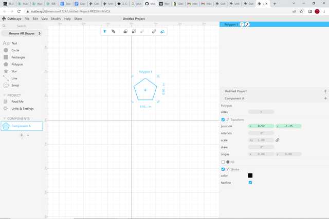
The first thing I did was drag a rectangle onto the design plane and dimension it.
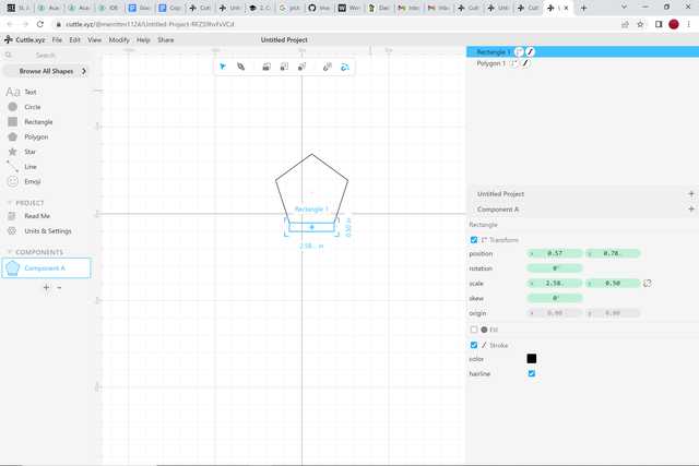
I then dragged in a rectangle and snapped it to fit the edges of the pentagon and dimensioned again.
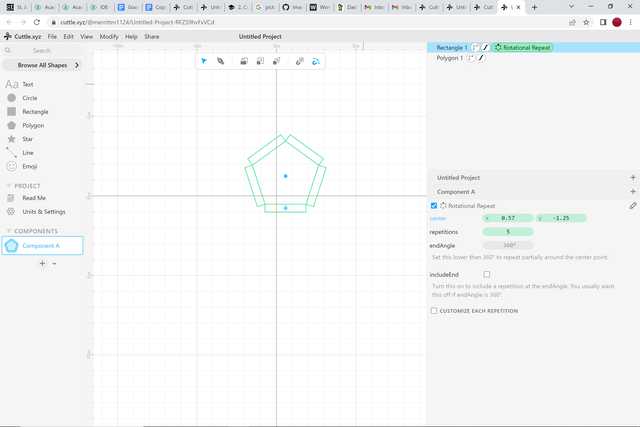
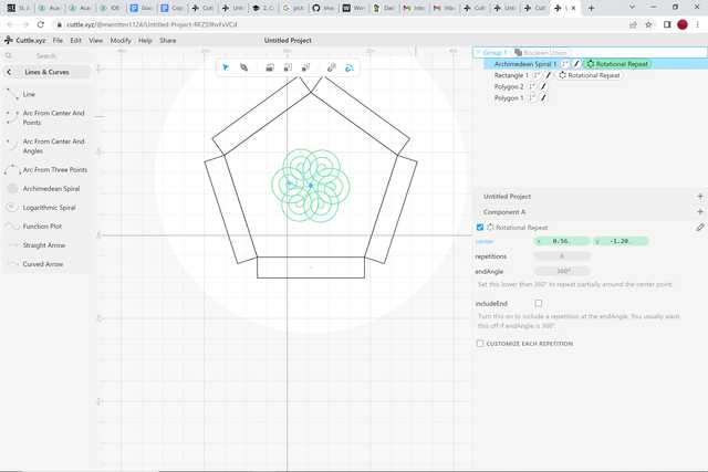
I used the rotational repeat tool then to put the rectangular tab on each side of the pentagon.
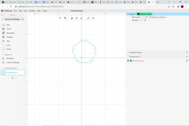
I then used the boolean union tool to connect the tabs to the pentagon shape
I then added designs and copied them using the rotational symmetry tool to finish the designs.
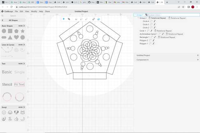
Here’s what my final design looked like with a downloadable svg below.

Gimp
Gimp is a raster design software, mainly meant for image manipulations. In gimp, I made a floating design of my initals. I learned a lot about GIMP’s layer tools, manipulation and creation tools, and general settings. For me, GIMP was very hard for me to navigate at first, but I was pretty quickly able to get used to it’s system of menus. I like gimp’s layer system, because it’s something I’ve seen before in many other softwares, like Corel Draw and procreate. I’ll probably use GIMP again if I need to manipulate or create raster designs, however I’d like to find an alternative to GIMP if i’m making small, simple changes. Here are some pictures from the design process of making my logo:
Pictures and steps.
The first thing I did was change my background color to black, I did this by going into the left color menu and selecting the background color.
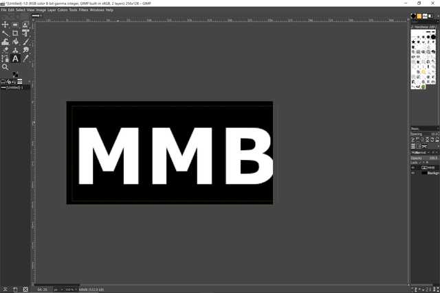
After that, I added some text into my background, I chose a thicker font so that it would be easier to work with later.
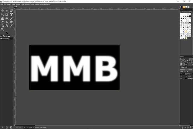 Next, I added a Gausion blur to my text by going to edit>blur>gausion blur
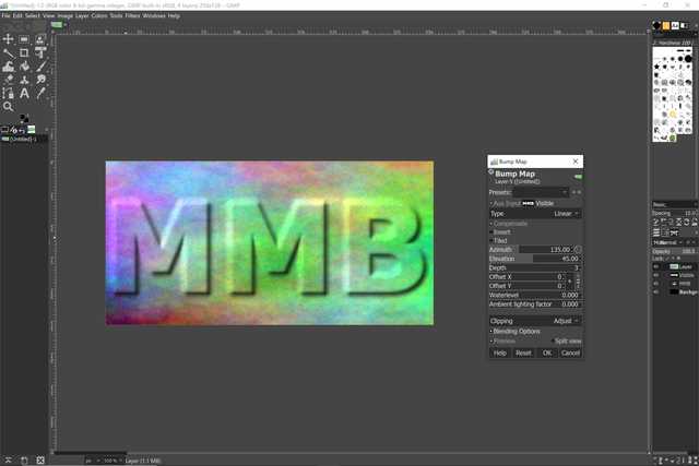 After that, I used the plasma plugin for GIMP to add the color that my text was going to be on I did this by going to Filters → Render → Noise → Plasma. In order for the text to show, I used the bump map feature to make an extruded effect on the text
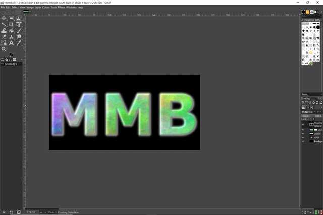 Next, I needed to make only the bump mapped text show, I did this by first creating a layer mask through Layer → Mask → Add Layer Mask. Then, I added a copy of the layer with what text I have into the layer mask, and anchored it to the same layer as the plasma effect.
 I then changed my background color by selecting the background in the left color menu, and then changing with the sliders until I was happy with it.
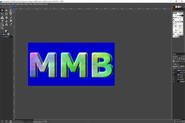 Finally, I did some final touches, I adjusted the color settings to make the text more clear by using the Gamma and whitepoint settings. I also created a drop shaddow by making an inverse of my text and then slightly offsetting it from the text above. Here is the final, downloadable product below.

FreeCad
FreeCad is an open-source, 3d design software. I’ve had previously 3d design experience with fusion 360, however, the FreeCad UI was much more daunting than what I was used to. To start, I used these tutorials. The first tutorial was just settings and general setup, where I got rid of a lot of the system dialouge from FreeCad. The 2nd tutorial was to create a small part that helped me learn using the part design and sketch tabs. The tools that I learned how to use were the shape tools, almost all of the constraint tools, the pad tool, the pocket tool, fillet, and projection. While freecad was confusing at first, I eventually realized that it’s not all that different from Fusion 360. All I was doing was creating designs, fully constraining them, and then turning them into a 3d output. While I still prefer fusion 360, as I have more experience with it, I can see how FreeCad could be just as powerful of a design tool. Here are some pictures and descriptions from the process of making my part.
Pictures and steps
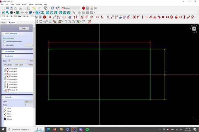 The first thing I did was enter the sketch panel and create a rectangle I dimensioned the rectangle using the vertical and horizontal distance constraints.
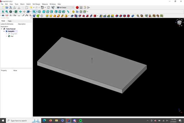 Next, I extruded the rectangle, in FreeCAD, this is called the pad tool, I extruded to a height of 5 mm.
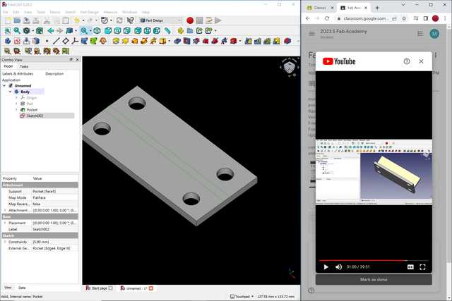
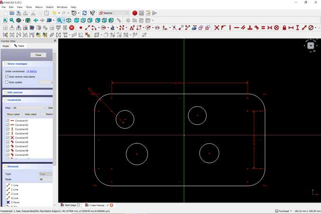 I then created 4 circles for the holes. I did this by going back to the rectangle sketch I created, and then used the circle tool to sketch out 4 circles. I also tried to add fillets in this sketch, but I realized that I was better off doing those at the end.
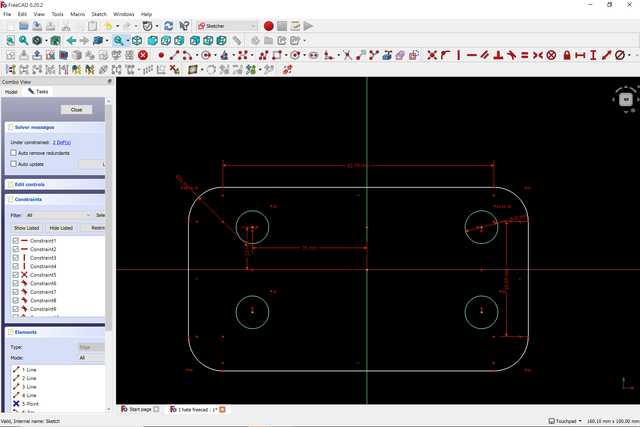 I then fully constrained the circles using a few different tools, I used the diameter tool first to define the size of one circle. After that, I used the equal tool to make all of the circles the same size. To make sure the circles were all in the same position, I then used the vertical and horizontal distance tools to set 2 of the circles a certain distance from the origin. I then used the paralell tools to make all of the circles in the same place.
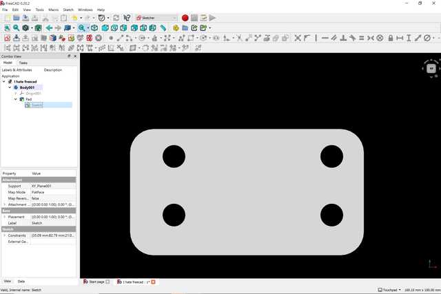 I didn’t need to use the hole tool to make it into holes, since it was on the same plane as my sketch.
 I got rid of my filleted edges, and then I added the rectangle for the extruded part on top of the piece. You can see on the right what it should look like after padded. I had to project geometry in order to snap the lines to the edge of the rectangle, which was a tool I’ve used a lot before in fusion 360.
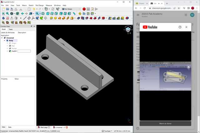 Finally, I filleted the top edges of the part in order to add the curvature. I also filleted some of the sharper corners in order to make my part look smoother.
Here is a download for this file
Designing a part of my final project: Fusion 360
Fusion 360 is a design tool that I am very familiar with. The part of my final project that I decided to design was the basket for the cart as well as the legs. Eventually, I’m going to add a joint to the middle of the legs so that I can simulate the legs folding. I’m also going to add wheels to the base. The tools that I used to make this design were sketch, extrude, projected geometry, constraints, move and copy, and plane from 2 edges. This didn’t take me long to create, and I’m definitely going to add the joints soon. I don’t have much experience with simulating moving parts in fusion, so I hope it’s something I’ll be able to learn in time from 3d scanning and printing week, so I can print a small version of the scisor lift system that the beach cart will use. Here’s some pictures and steps that I used to make the cart.
Pictures and steps
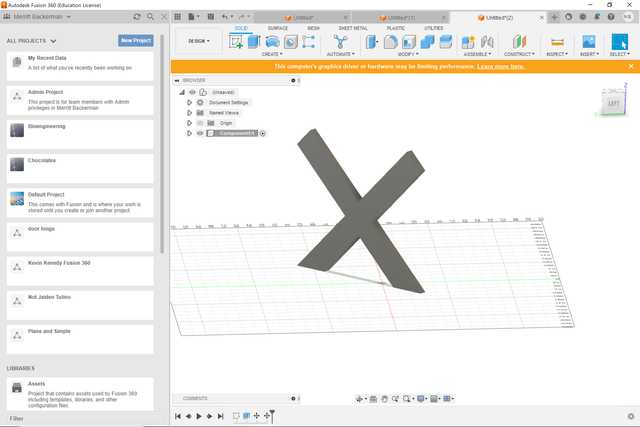
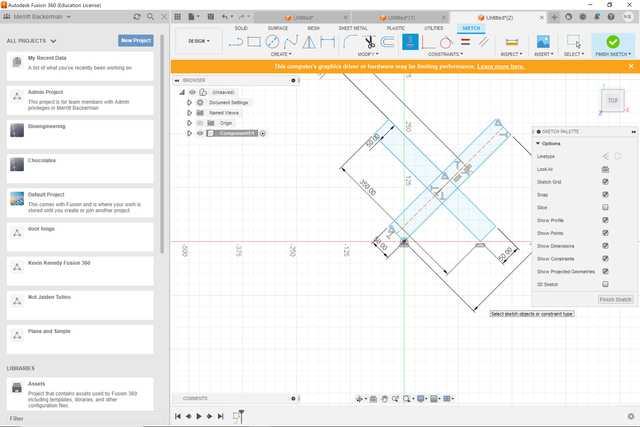 The first thing I did was create the 2 crossed rails that will eventually be held by a joint, so that the cart can fold. I used a lot of constraints and dimensions so that they crossed evenly with each other.
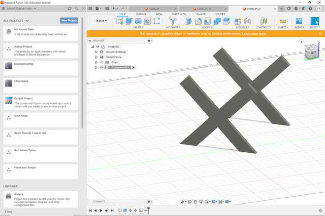
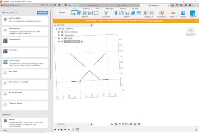 I made the crossed rectangles flat at the bottom and extruded.
 I had designed the piece on the wrong face, so then I rotated the piece and snapped it onto the right plane.
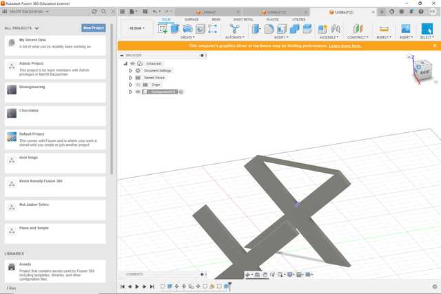
 I then created a copy of the rails, so that the basket can rest on top of the rail.
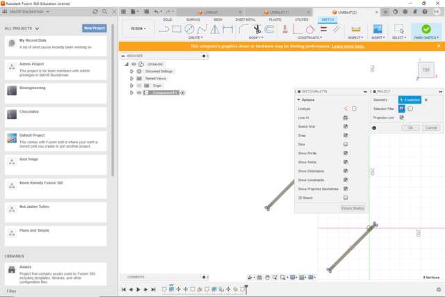
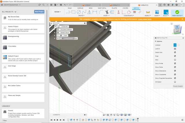
 I then created a bar across the top of the X for the basket to rest on. I used the plane across 2 edges feature, and then connected the edges together using the line tool. I extruded the bar down, and moved it to join into the crossed bars.
 Instead of just making the basket completly filled in, I wanted to create a barred bucket. I did this by first projecting the edges from the base, and then creating small extruded pieces that wrap around the rectangle.
 At this point, the bars I made were floating, so I made pillars at each corner to support the bars. I made small rectangles in the base of the basket, and then extruded it and joined it to be in between the bars
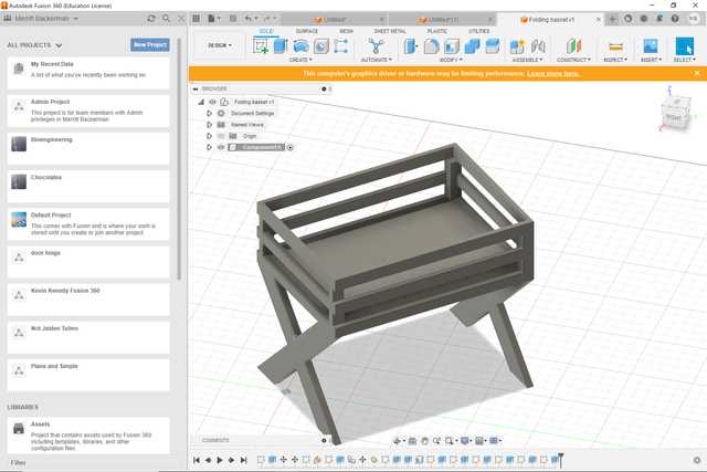 Here’s the complete version of my basket.
Other tools I’ve used in the past
Corel Draw
Corel draw is a 2d vector design software. For more complicated designs, I will probably using Corel Draw instead of cuttle. Corel draw has more accesible advanced features, a more common layer systems, and other features that make it easier for more complex designs. For next week, which is computer controlled cutting, I will be using Corel Draw for all of my laser cuts.
Tinker CAD
Tinker cad is a simple, browser-based design software. If I need to design a small, 3d part that I know will only need basic shapes, I’ll probably use tinkerCAD. TinkerCAD doesn’t use a 2d to 3d system, instead you just drag and drop 3d shapes onto a plane, and then dimension it. An example of a design I’ve made in tinkerCad previously is a small bracket to hold a solenoid on a wall.
Inkscape
Inkscape is a open-source vector software, that I find similar to Corel Draw. Because I might not always have access to Corel Draw, as it’s a paid software, I might be using Inkscape occasionally if I don’t have access to Corel Draw.