3. Computer controlled cutting
This week I characterized aspects of the lab’s laser cutters in a group, as well as designed and cut my own parametric press fit construction kit in Fusion 360, and designed a multi-layered sticker in silhouette studio and then cut it.
Group project
This week we had our first group project, where we characterized different factors of our laser cutter you can find that work here
Individual Work-Press fit toy
The first thing that I did for this week was designing a parametric, press-fit toy. I decided to just make shapes that would fit together to build different designs. I used the slot joint with no chamfer to join the pieces together, because it fits pieces well and is easy to make parametric. For my CAD software, I decided to do Fusion 360 because i’m familiar with using it’s parameters and constraints.
Design steps
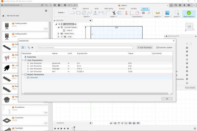
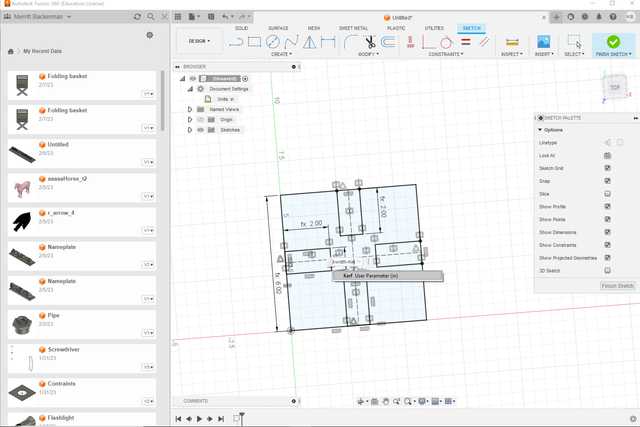
To start, I created a few parameters that I knew I would need.
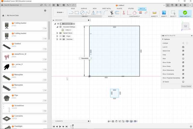
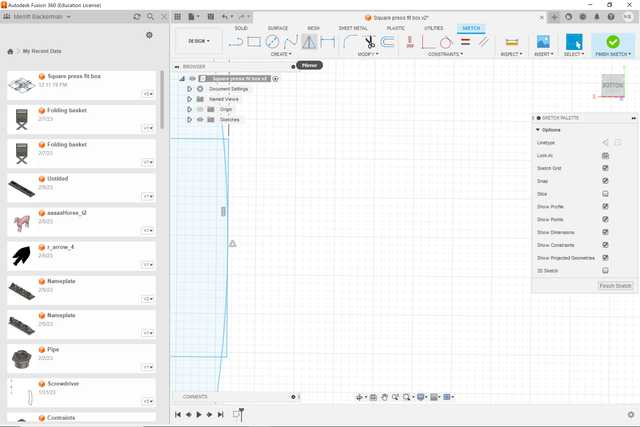
Next, I created a square using the parameters I just created
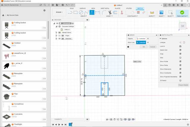
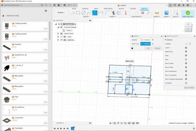
Then, I created a tab with parameters named tablength and tabwidth, which I later changed to materialthickness. I used the midpoint constraint to attatch the tab to the square, and mirrored it so that the tab is on all sides of the square. I also changed the materialthickness to the thickness of the material and dimensioned the tab as materialthickness-kerf to account for the kerf.
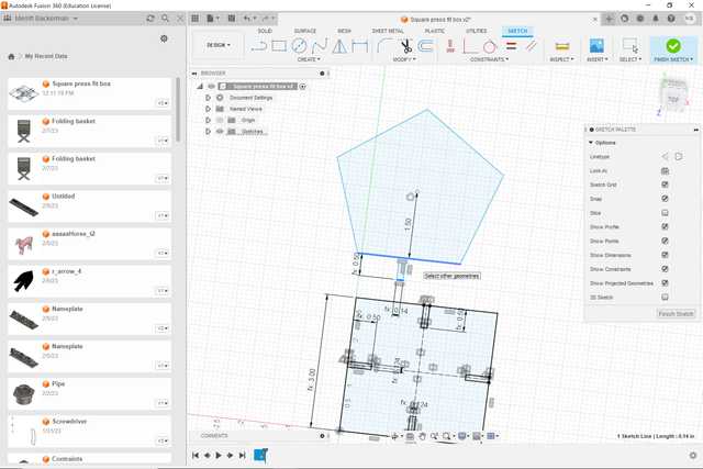
Next, I created a pentagon piece, I did this by first creating a pentagon and making a new dimension pentagon radius to define it. I also made a single tab with the same dimensions I’ve been using
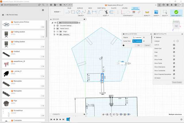
I then used the midpoint constraint to attatch an edge of the tab to the middle of my pentagon, and used the circular pattern tool to repeat the tab on every side.
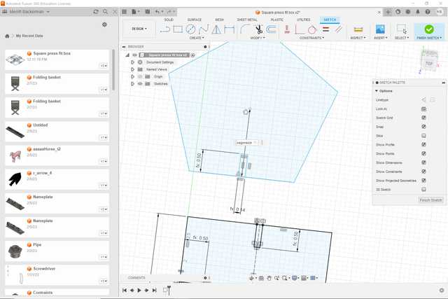
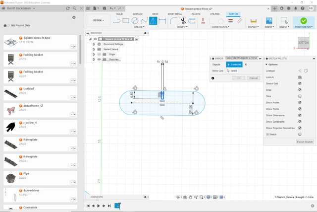
Next, I decided to make a slot shape, I made a slot and made a new parameter with it’s size. I also made a tab and attatched it again using the midpoint constraint
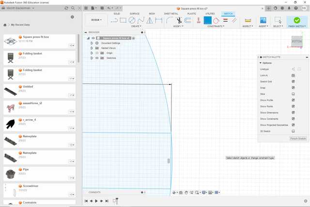
On the curved section, I tried to do the same thing but ran into a problem
The tab extended over the midpoint of the curve, so it wouldn’t be the same size of a hole as the other tabs. To fix this, I made a coincident constraint between the tab and a point on the midpoint of the curve. This placed that tab inside the curve so it looked like this.
Cutting my design
To cut my design, I used an epilog fusion m2 and cut with a power of 100 and speed of 40. I used the same material thickness value as my value from the fusion 360 parameter, and then cut.
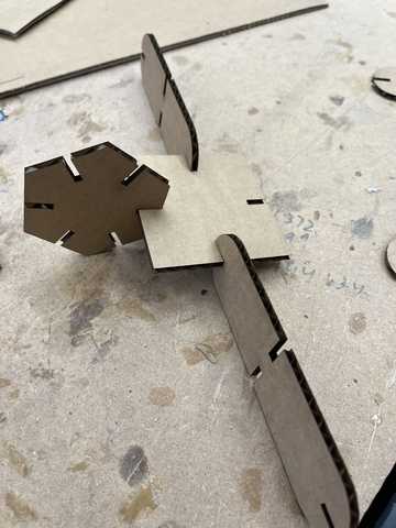
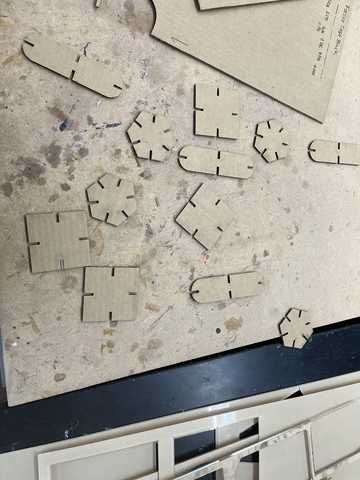 My pieces
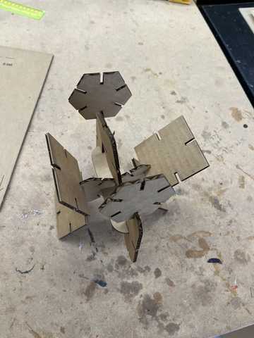
Building with them
File
Click here to download the lasercut file file as a .dxf.
Final Thoughts
This unit helped me learn a lot about Fusion 360’s sketch constraints and parametric features. The designing process felt very intutive for me. Since I am experienced with all of the laser cutters in our lab, the cutting process was also very easy, our group project helped me find the best settings for cardboard to minimize our laser cutters kerf, which we measured. This made my slotted joints fit together very well.
Vinyl Sticker
The next thing I did for this week was use our vinyl cutters to create a multi-layered sticker. I cut my design on a silouhette cameo cutter, so I used silhouhette’s own software, silhouette studio.
Making my design
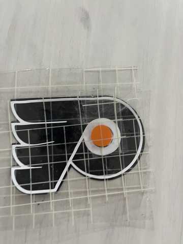
The design what I decided to do was the logo of the philidelphia flyers, my favorite hockey teams. Before even opening the software, I came up with a plan. On what the layers of my sticker would be. I planned to start with a black background layer to create the black trim on the very outside of the logo. Then, I would do a white layer to create the inside trim and circle around the orange dot. After that, I would create another black layer for the inside, and finally an orange dot in the middle.
Cutting and putting together.
To Cut my sticker, I followed this workflow created by our lab:
-
Get cutting mat, making sure that one side is still sticky
-
Cut a piece of vinyl from roll, or use scrap vinyl. DO NOT T OR L CUT
-
Place piece of vinyl onto cut mat aligned with the upper left corner
-
Place the cut mat on to the edge of the machine so that the left and right edges of the cut mat are lined up with the blue arrows
-
Click “Load” on the machine’s screen
-
Open silhouette studio software, select your design, and then select “Cut”
-
Select your cut options, either outline, whole shape, or selected shape. This will either cut an outline of your design, the whole design, or selected parts. Most stickers will use the outline settings
-
Select settings, the settings should default to “Vinyl, glossy”, this is what most vinyl in the lab is, and has the appropriate cut depths and speeds pre loaded. If using another material, select that material from the preset options.
-
Once ready, hit “send to machine”, the machine should start cutting automatically
-
When design is finished, select the “Unload” button, and take the vinyl off of the cut mat and put it away
-
Grab weeding tools (Dentists hooks, utility knife), scraper, and transfer paper big enough to fit your sticker.
-
Use weeding tool to carefully lift up the excess vinyl around your design until you are left with just your design with the rest of the vinyl peeled off
-
place transfer tape on top of the sticker, and use the scraper to press the transfer tape onto the sticker until you can lift it up off the paper
-
Put back tools used for weeding.
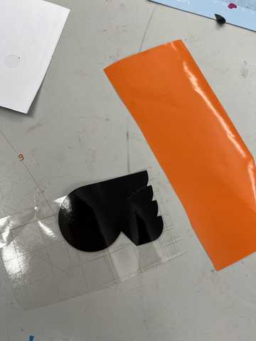 The first bottom layer
 The top layer overlay
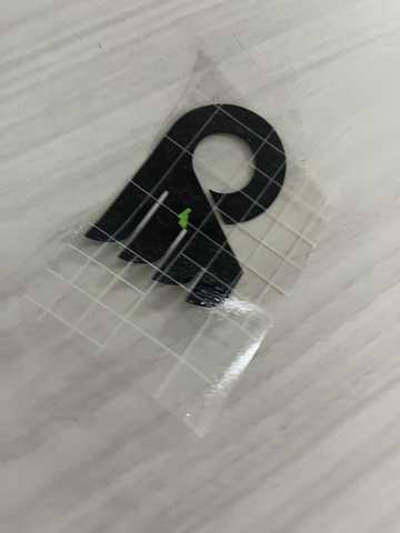
 White trim and circle
Once my layers were all put together, I peeled off the transfer tape to get my final sticker.
Final thoughts
I was familar with using silouhette studio and using the vinyl cutters, but before this I had never made a multi-layered sticker. The layering process was pretty simple though once I broke things down into each layer, and then put them together into my final sticker.
File
Click here to download the sticker as a silouhette studio file.