Final project
Slide and Video- The Fab Wagon

What does it do?
The Fab Wagon is a carrying wagon designed for Griffin Orsinger’s Seeed Box. It is controlled by a bluetooth gamepad, turning the wagon via a differential drive system to two motors driven with an l298n motor driver. It also has object detection using the vl53l1x time of flight sensor, and an onboard orientation sensor.
Who’s done what beforehand?
My project was originally inspired by Hackster Shack’s follow me cooler, which used an arduino uno, bluetooth module, and gps board to follow a user’s phone using GPS coordinates. While at first I planned to also use a GPS following system, as well as the HC-05 bluetooth module, my project changed so that the only idea I used from them was part of the physical design- a differential drive system with a caster wheel in the back. I couldn’t have done my project without a few key libraries, which streamlined my coding process. The bluepad32 and VL53L0X Libraries simplified the coding processes for bluetooth control and object detection, and parts of their example codes are included in my main code.
What materials and components were used, Where did they come from, How much did they cost?
Here is my BOM of all materials and components used, where they were sourced from, and how much they cost.
What parts and systems were made?
My project can be broken down into the following systems
Steering system: Includes motors, motor driver, bluetooth gamepad, wheels, electronics board.
Object detection: Includes ToF sensor, motor driver, motors, electronics board.
Mechanical system: Includes wagon body, wheels, motor mounts, wheel axels.
Project management: Includes electronics box, wiring.
Creating my final project board
For my final project, I needed to create a board to connect to the following components, which can be found in my BOM:
- A seeed Xiao ESP32S3- my microcontroller to control my project, I chose this because it has built in bluetooth
- An l298N motor driver to control the speed and direction of the motors
- An Adafruit VL53L0X to automatically stop before obejects
- An Adafruit BNO055 to detect orientation
Creating my final project board- part 1: schematic
I used kicad to create my board and followed the workflow that I documented during electronics design week, here is my schematic:
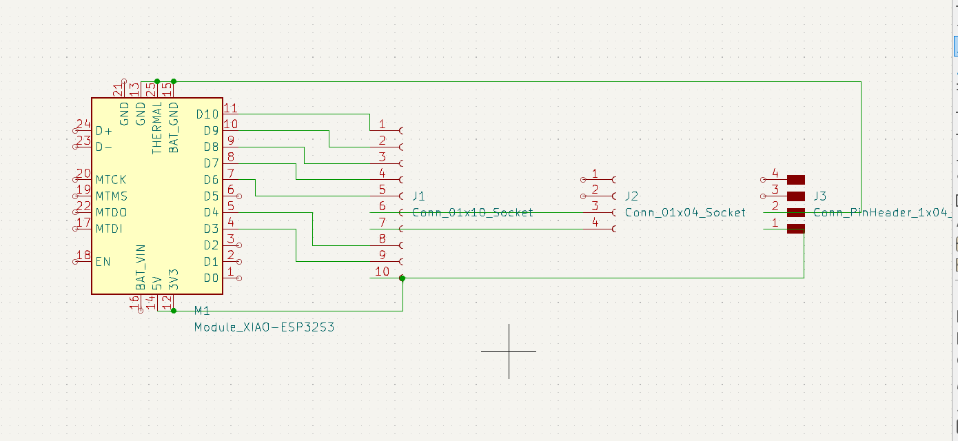
Instead of using some of the actual components, I used headers, since the components would be either soldered onto the board via headers or wired from sets of headers.
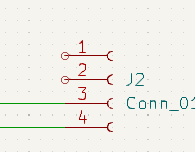 This side of the headers is the orientation sensor, and where the two I2C Pins will go
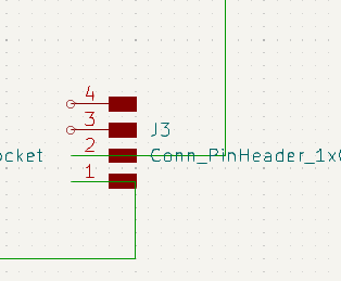 This side of the headers is also part of the orientation sensor, where the power and ground will be
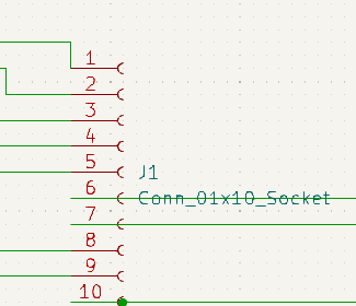
The header here will include pins for the motor driver, power, ground, and I2C for the Time of flight sensor
Creating my final project board part 2- PCB.
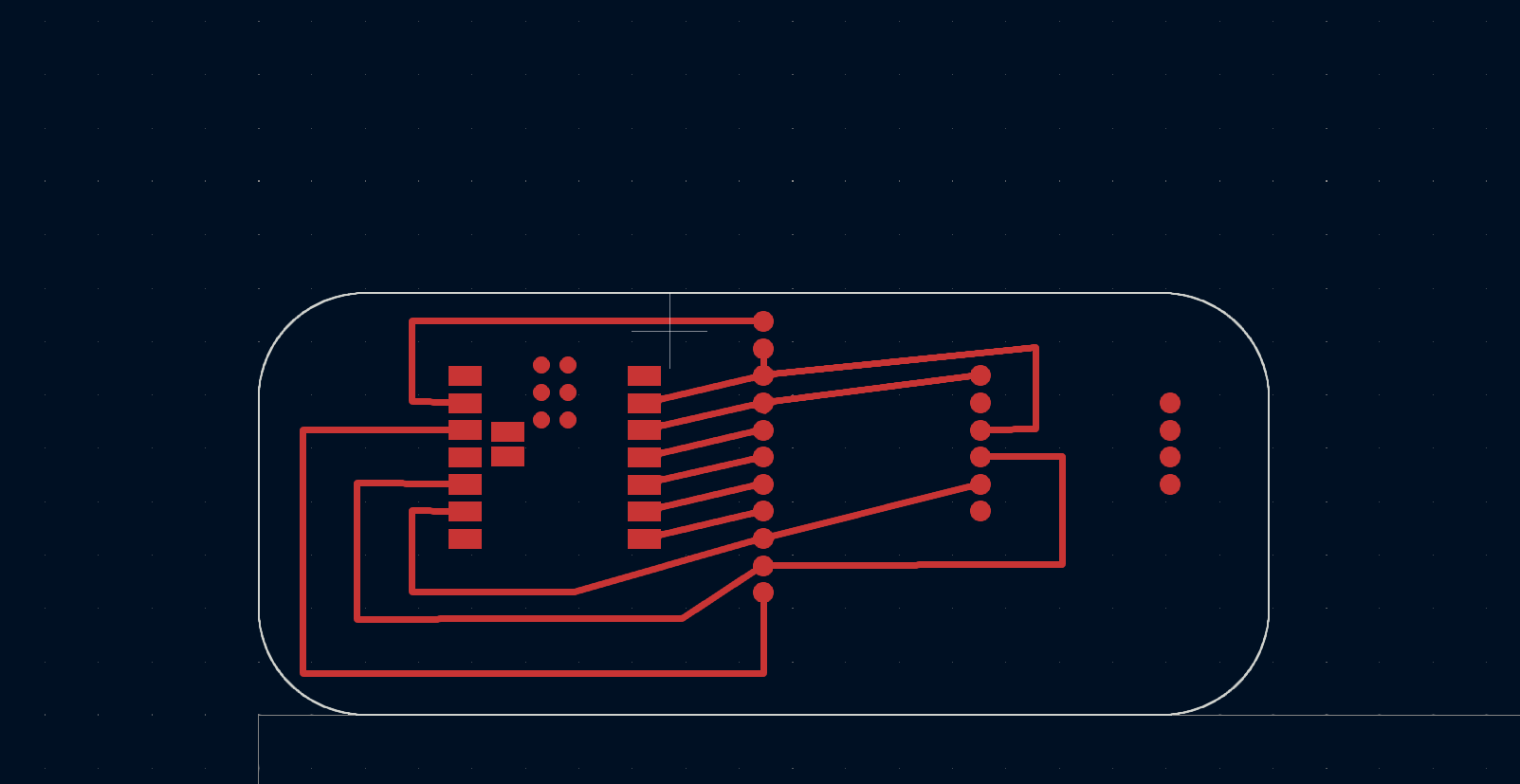
To create my PCB, I assigned the PCB components to the footprints, and then routed my design. I used calipers to make sure I had the spacing between the 2 sets of headers right, and then did my wiring. I was able to avoid using 0 ohm resistors in my design.
Creating my final project board part 3- milling
I documented milling my final project board for my week 4 documentation, which you can find here
Changing plans from PID to bluetooth control
Since I struggled with PID, I made a new decision with how to control my wagon: Via Bluetooth control. I documented here.
Object Detection-
In order to detect objects, I have a time of flight sensor included in my project, I’ve documented using this sensor during input week, So I was already familiar with using it. I added the following parts into the bluetooth control code that I documented during week 14. I wired the sensor the following way SDA>SDA, SCL>SCL, GND>GND 3v3>VIN
Before setup: Sets variable for stop distance
const int stopDistance = 100; // Distance threshold to stop the motors (in mm)
In my setup code: Initializes sensor
  // Initialize the VL53L0X sensor
    if (!lox.begin()) {
        Serial.println(F("Failed to boot VL53L0X"));
        while (1);
    }
    lox.startRangeContinuous();
}
In my loop: Function to print stop distance to the serial monitor for debugging, and check if distance is less than stop distance. If the distance is within range, then the function to stop the motors is called.
bool checkDistance() {
    uint16_t distance = lox.readRange();
    Serial.print("Distance in mm: ");
    Serial.println(distance);

    if (distance < stopDistance) {
        stopMotors();
        Serial.println("Object detected! Motors stopped.");
        return false;
    }
    return true;
}
After adding these parts of code to my final project code, I was able to get the following results:
Later on in the project, I changed the distance parameter to be a little further from the wagon by changing the stopDistance value.
Mechanical System
The mechanical system includes the physical body of the wagon, the motor mounts, the wheels and wheel mounts.
Creating the Wagon body- CAD
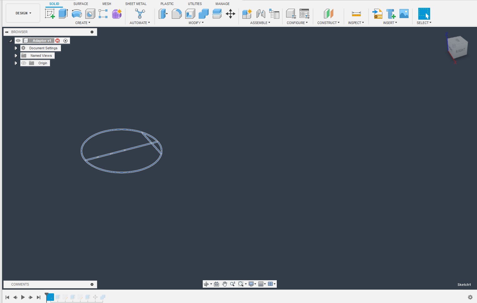
For my CAD design I decided to use Fusion 360.
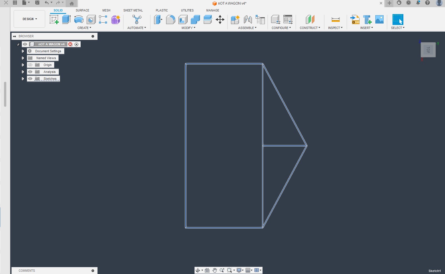
I started with a rough outline of the wagon, using dimensions from Giffins project for the design of the bed
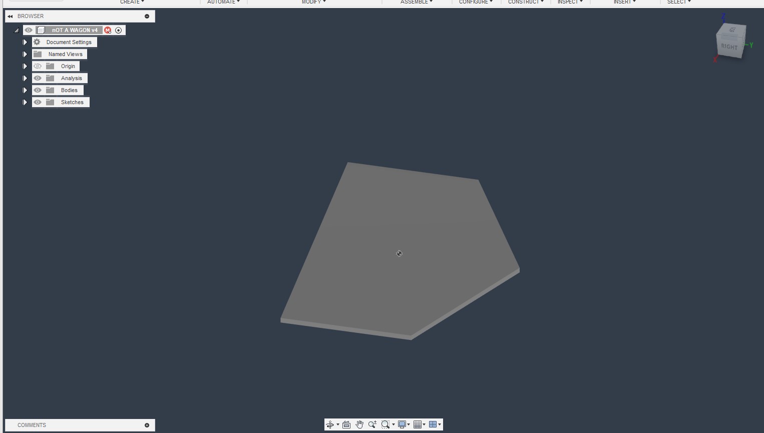
I then extruded the shape to the height of the material I was using
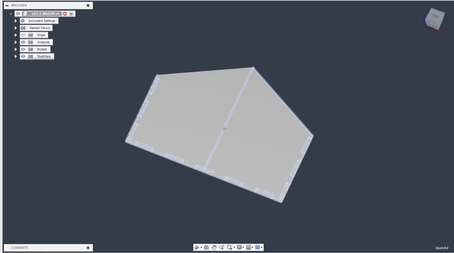
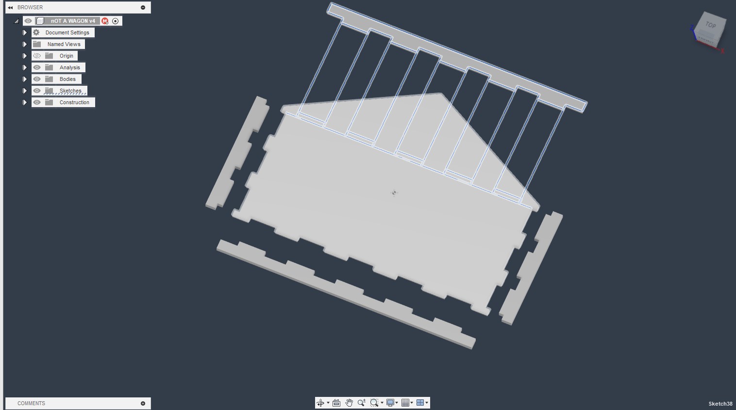
I then created a sketch of rectangular tabs on the front
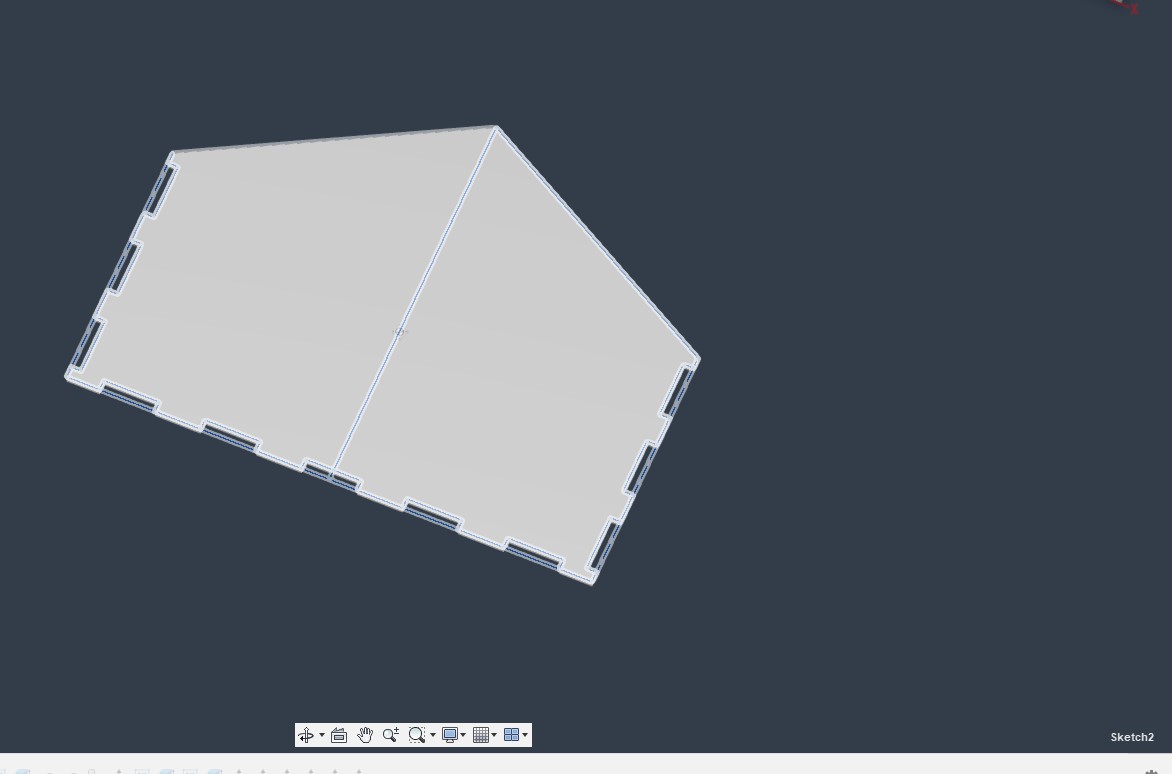
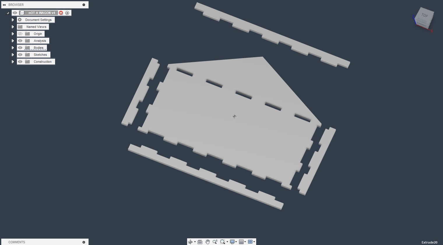
I extruded the tabs through the bottom of the wagon to make them into holes
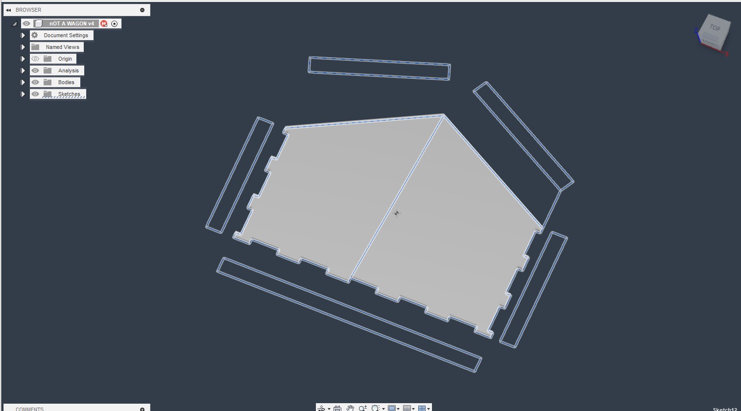
I then created rectangles for the side pieces
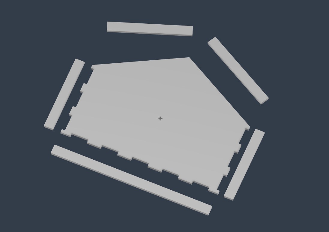
I then extruded these pieces
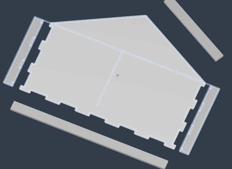
I added tabs again
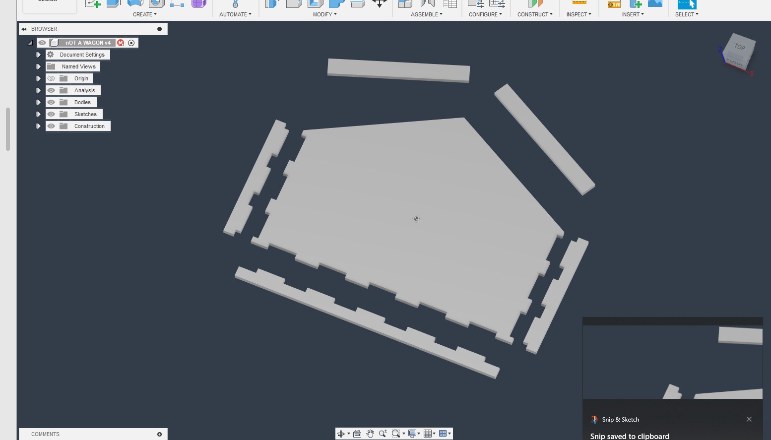
And extruded down again to make holes.
I got rid of the top 2 pieces, as I realized I needed a rail on the top edge of the rectangle to keep the seeed box in place. I created tabs and extruded them below the wagon
I then created tabs on the wagon’s main body
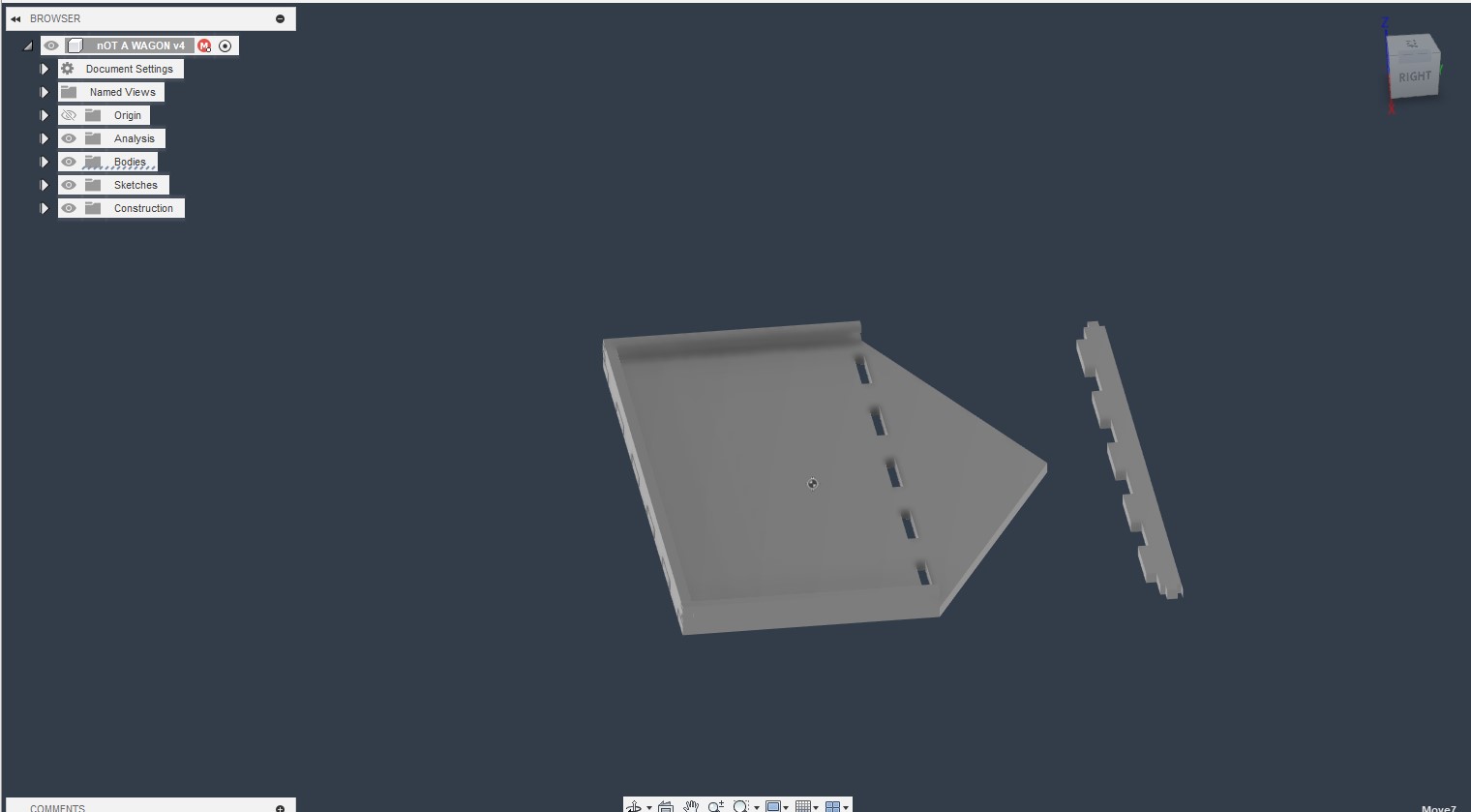
Here’s what the pieces looked like when fit together.
Creating the wagon body- CAM
For CAM I am using Vectrics aspire, and am following roughly the same workflow that I used in week 7- Computer Controlled Machining.
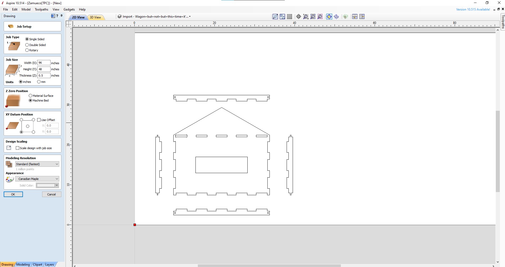
Setting up according to the machine bed size and material size, I am using .5 inch plywood.
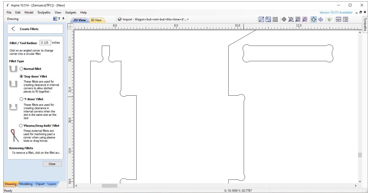
Like my last project, I also used dogbone fillets for the press fit pieces so that the machine can cut a sharper corner.
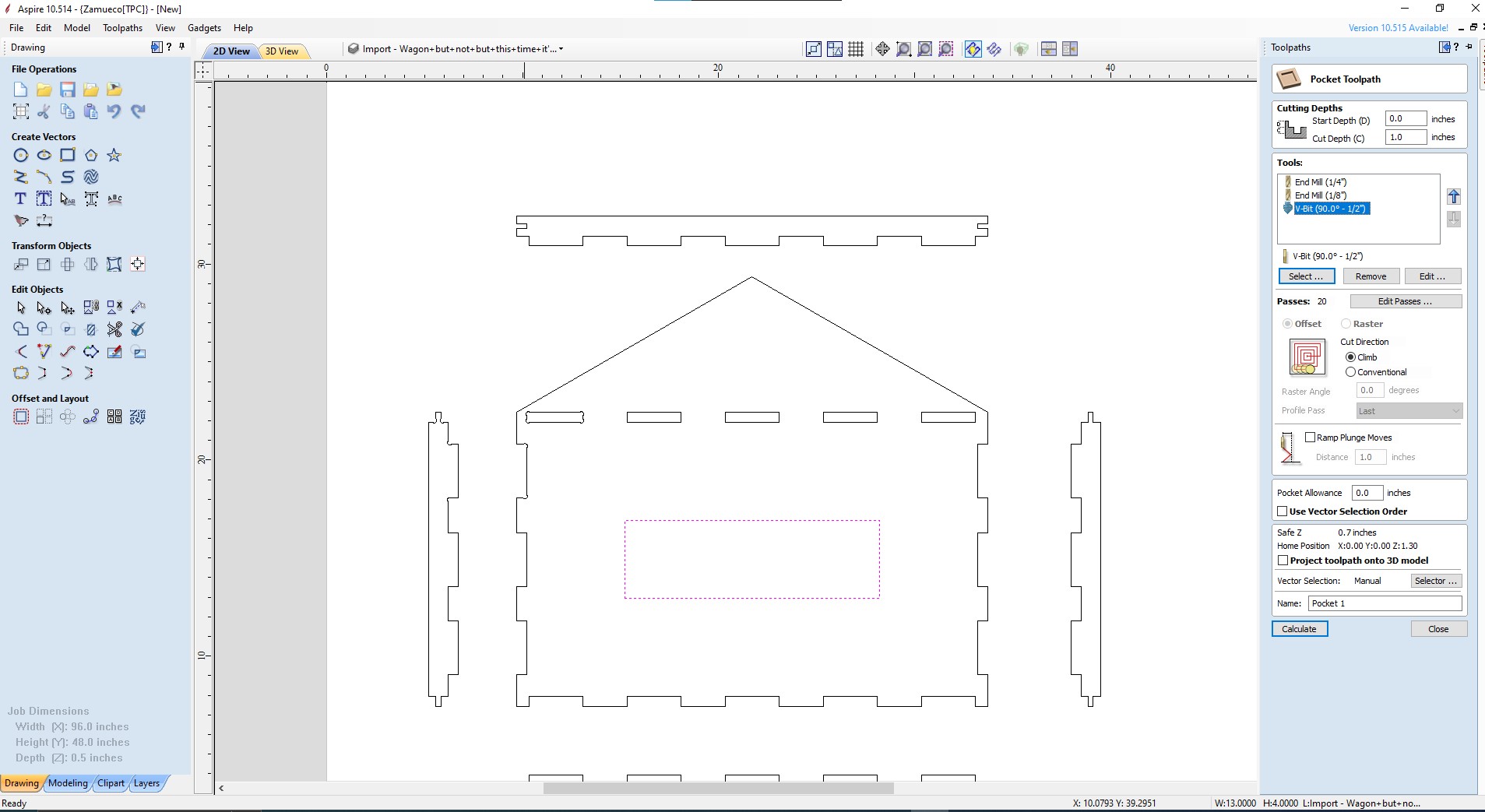
I then created a pocket toolpath for the middle hole in the wagon, I’m using a 1/2 inch bit since the cut doesn’t need to be precise.
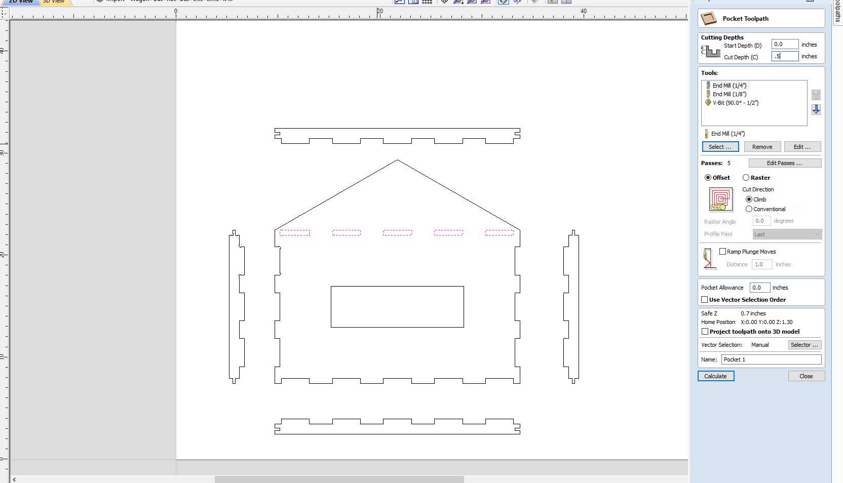
I then created a 2nd pocket toolpath for the holes in the middle of the wagon, I used a 1/4 inch bit for this though because it is for press fit pieces, and needs to be more precise.
I then added a profile toolpath for the pieces of the body of the wagon. I had to make a few changes to this toolpath. I inserted ramping to make sure the tool is gently inserted into the material, and also decreased the amount of passes that the tool went through in order so save time.
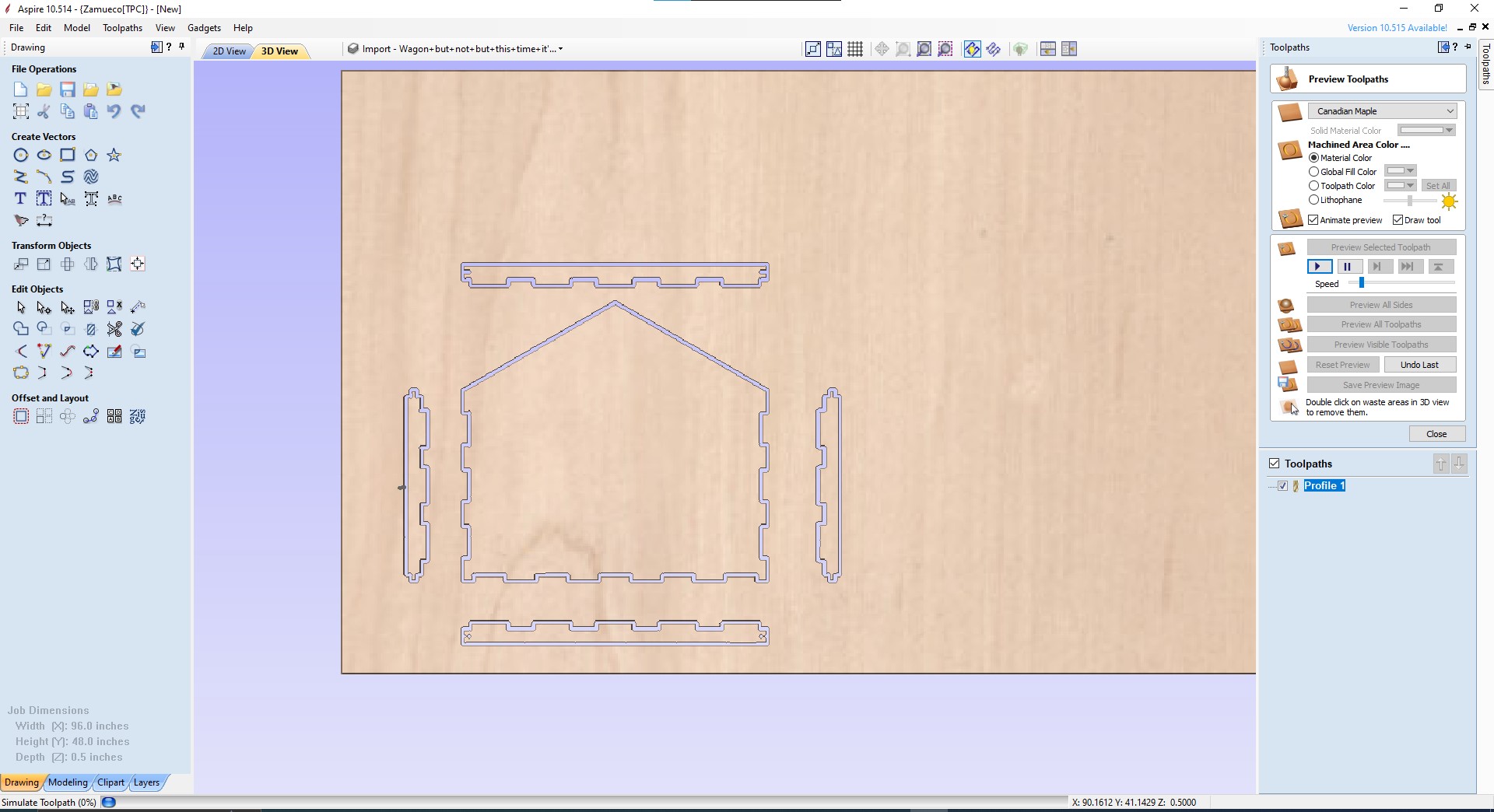
Finally, I previewed my toolpaths to make sure everything looked right.
Creating the wagon body- milling.
To mill, I followed the same workflow that I did cutting my other project with the only change being that I had to perform a tool change. In order to do this, after the first cut, I took the bit out, and reset the zero on the machine again after putting the next bit out.
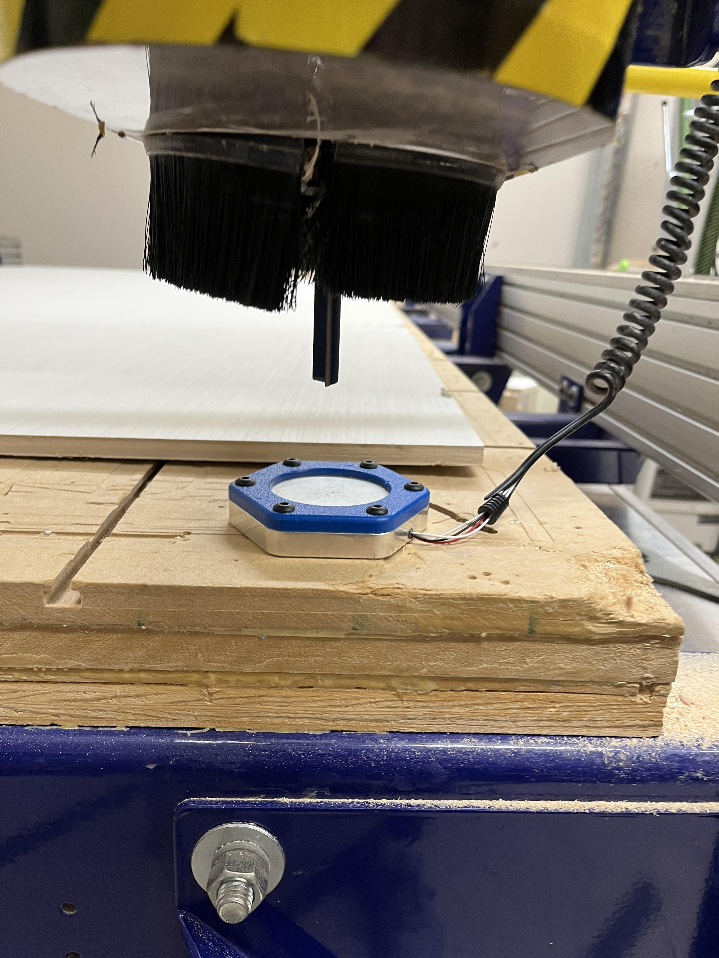
Zeroing the bit
Cutting out a tab
Creating the wagon body- assembly
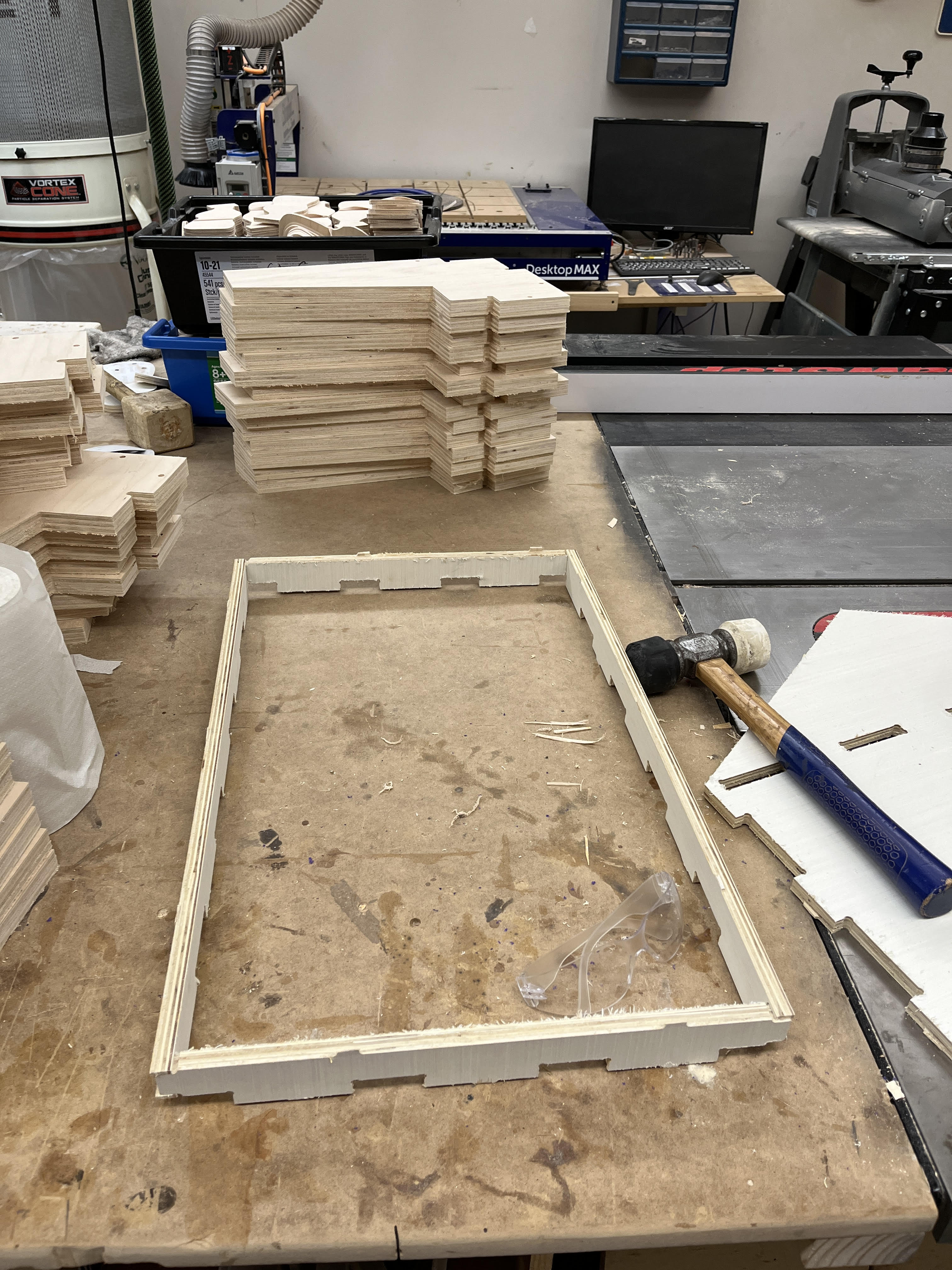
To start, I assembled the frame of the wagon by using a mallet to secure the press fit pieces together
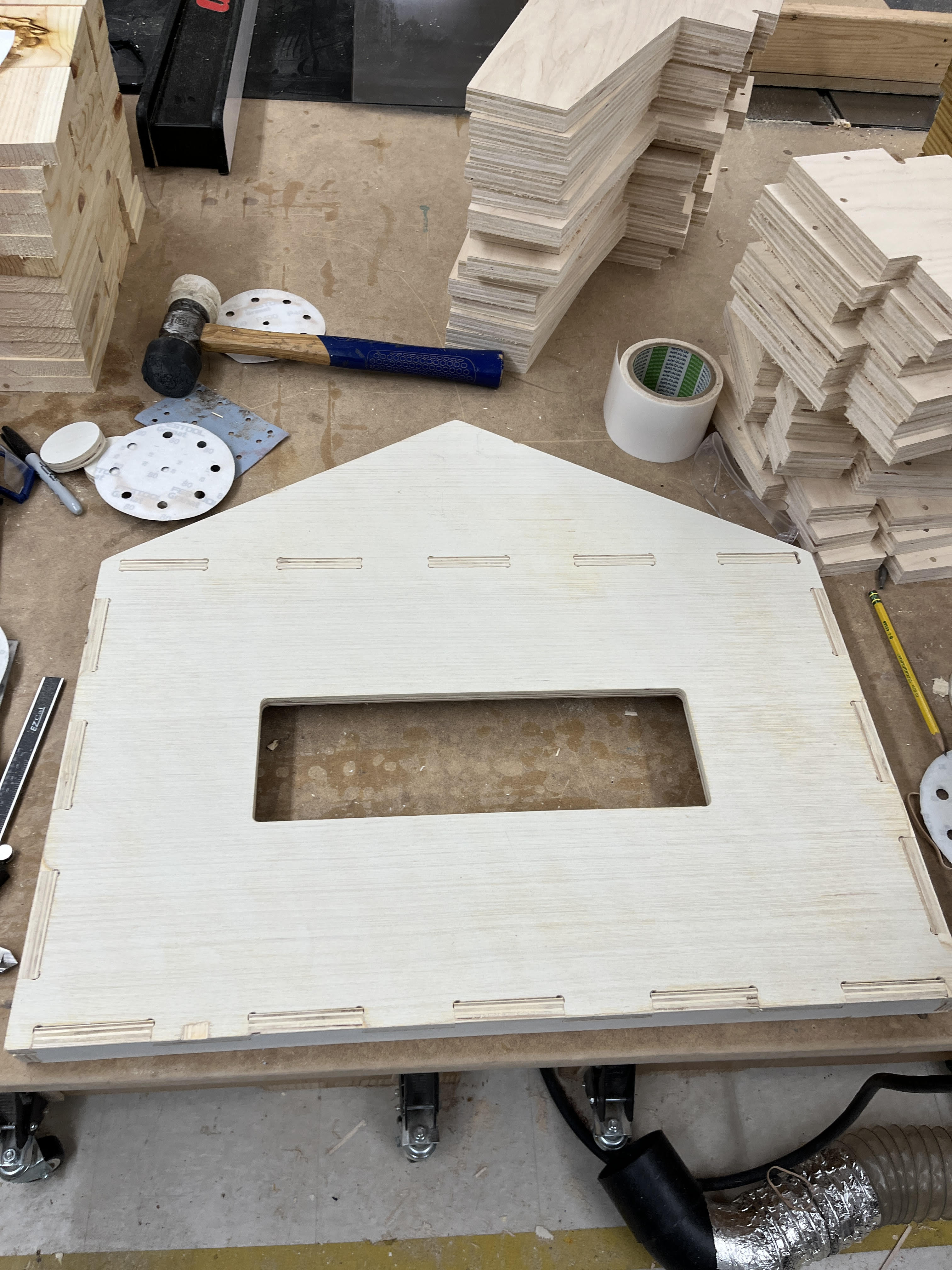
I then took the bottom piece of the body and hammered all of the tabs in. I also took my motors mounts and placed them roughly where I wanted them to be on the wagon. I marked these spots and then drilled holes using a 5/18 inch drill bit for M3 bolts to go through.
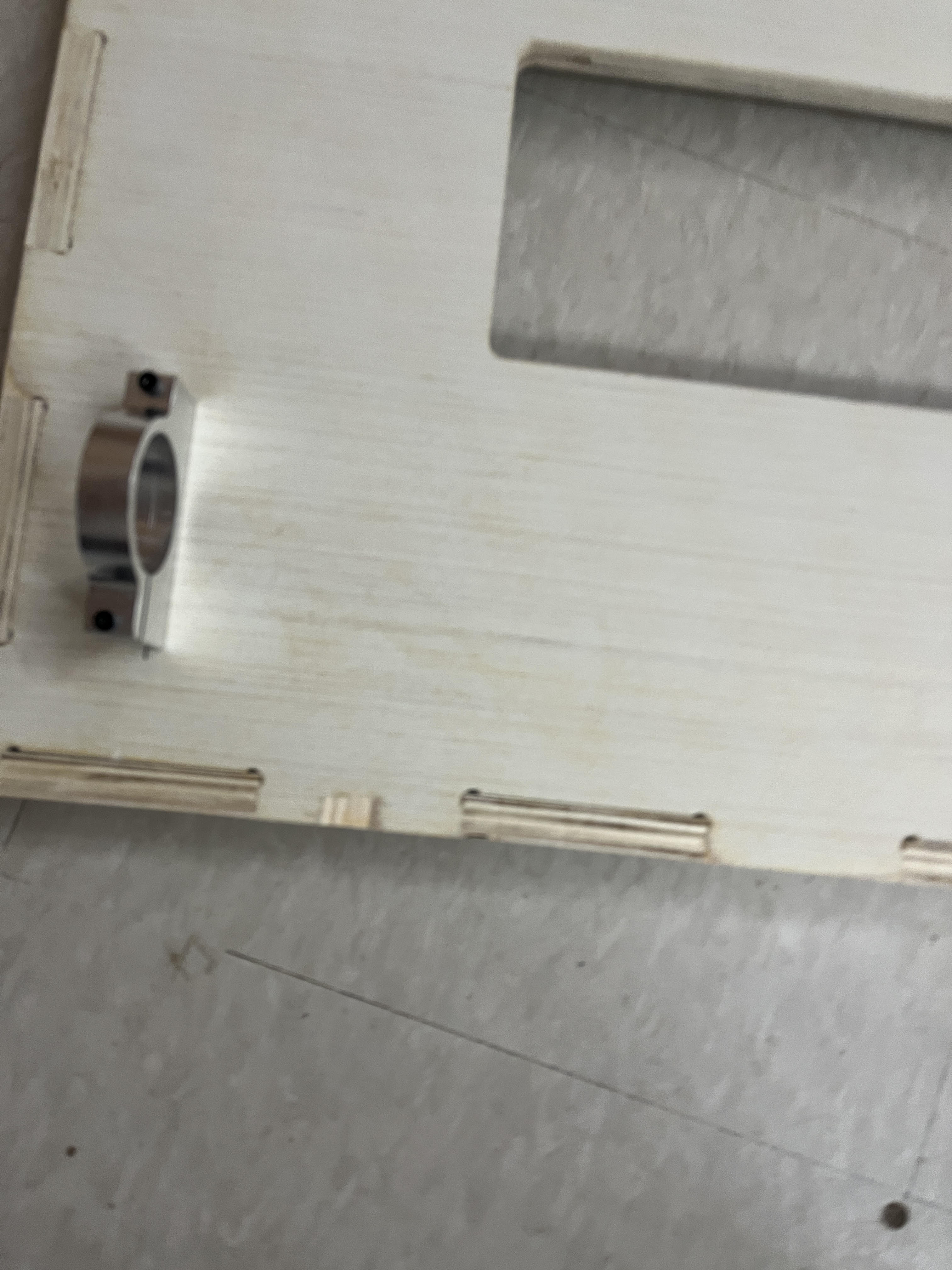
The motor mounts on the bottom of my design, I placed 2 M3x40mm screws through the holes, and put a lock nut on the other side.
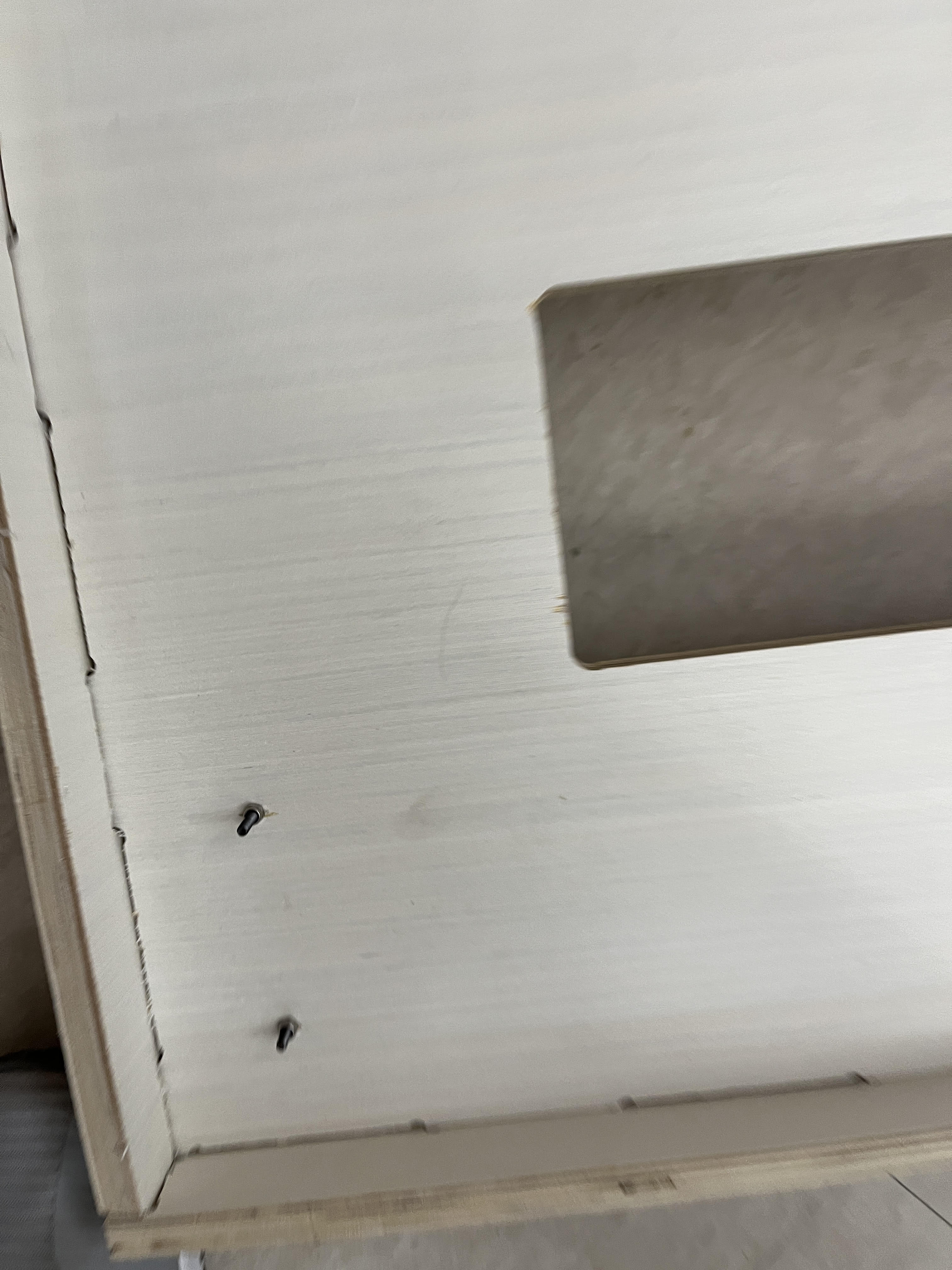
The motor mounts from the top
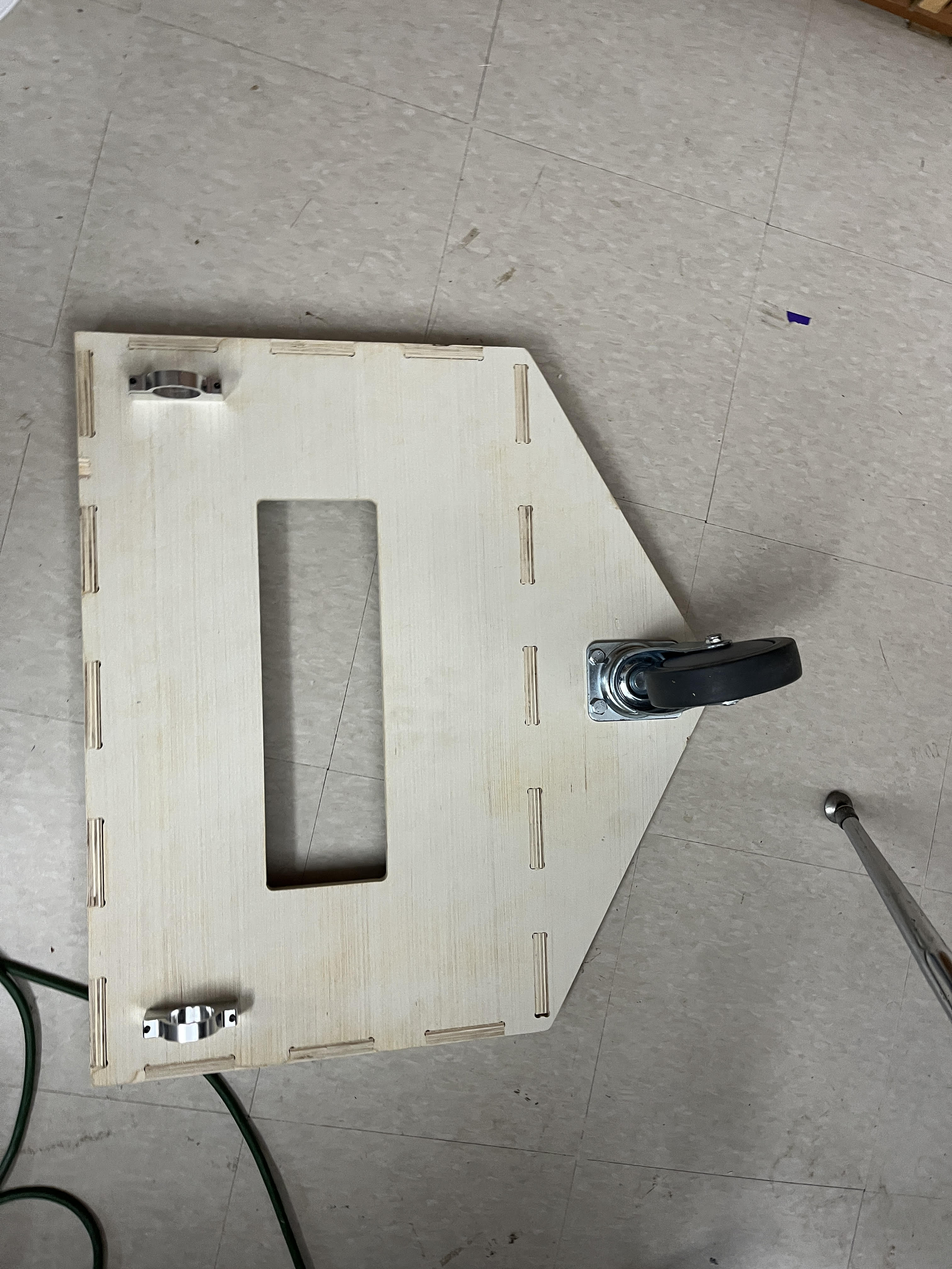
I then took my caster wheel and did roughly the same process. I drilled 4 holes where I wanted the caster wheel to be, inserted larger bolts through each hole, and then screwed nuts to the top.
Creating the wagon body- wheel mounts.
To attatch the wheels to the motors, I’m creating 3d printed parts to go into the wheels with very tight clearences to fit the motor D shafts. If the fit is right, with some epoxy, the motors should be able to hold the load of the seed box.
I referenced the Tetrix Motor Data Sheet In order to find the specifications for the length and height of the d shaft of the motor, I then created a sketch of it an extruded it.
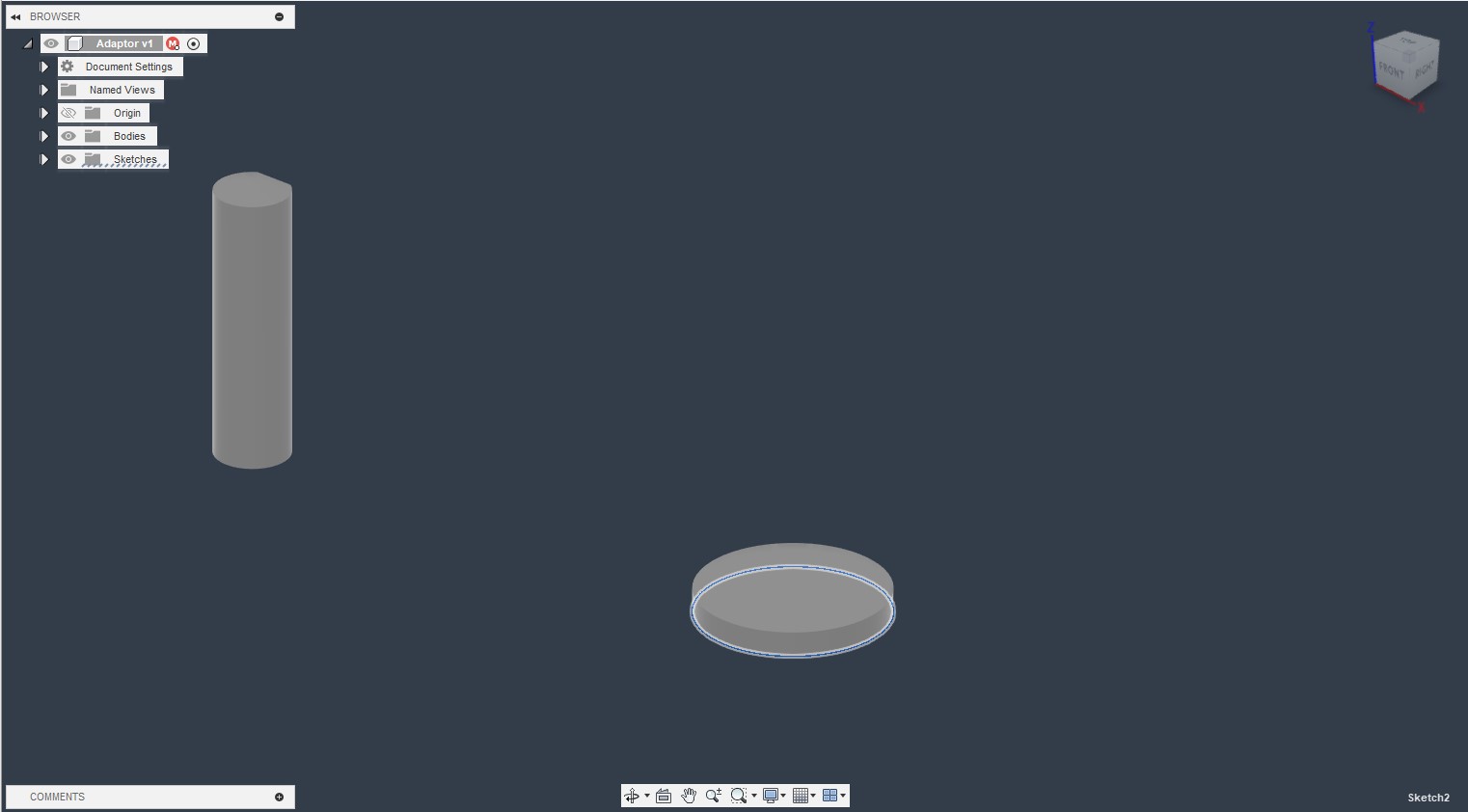
After creating the D shaft, I created the part of the mount to go inside the wheel. Using calipers, I measured that the wheel has a short outer hole, and a skinnier, longer inner hole. I created and extrueded a part for the outer hole first.
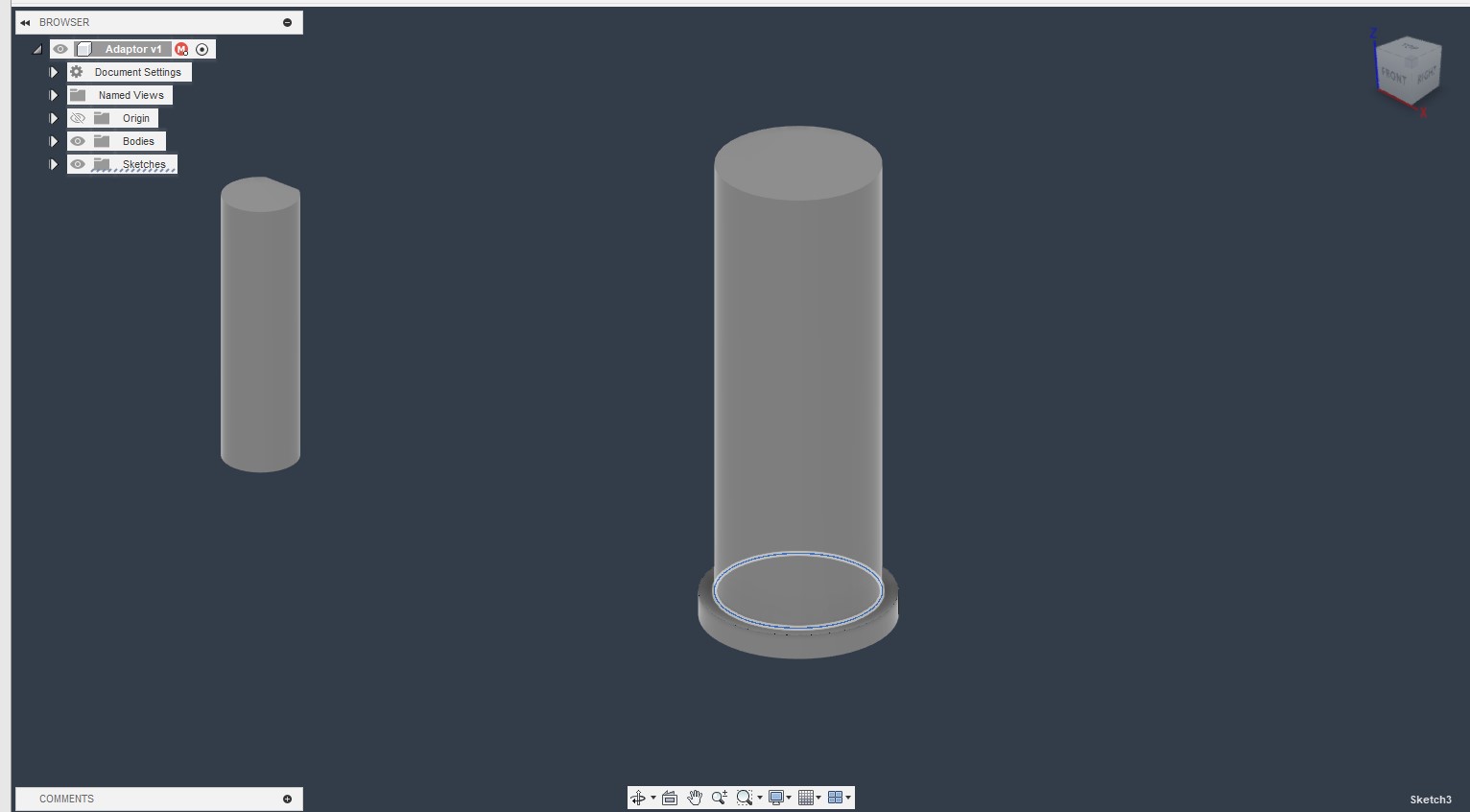
I then added a smaller circle sketch and extruded it for the inner hole.
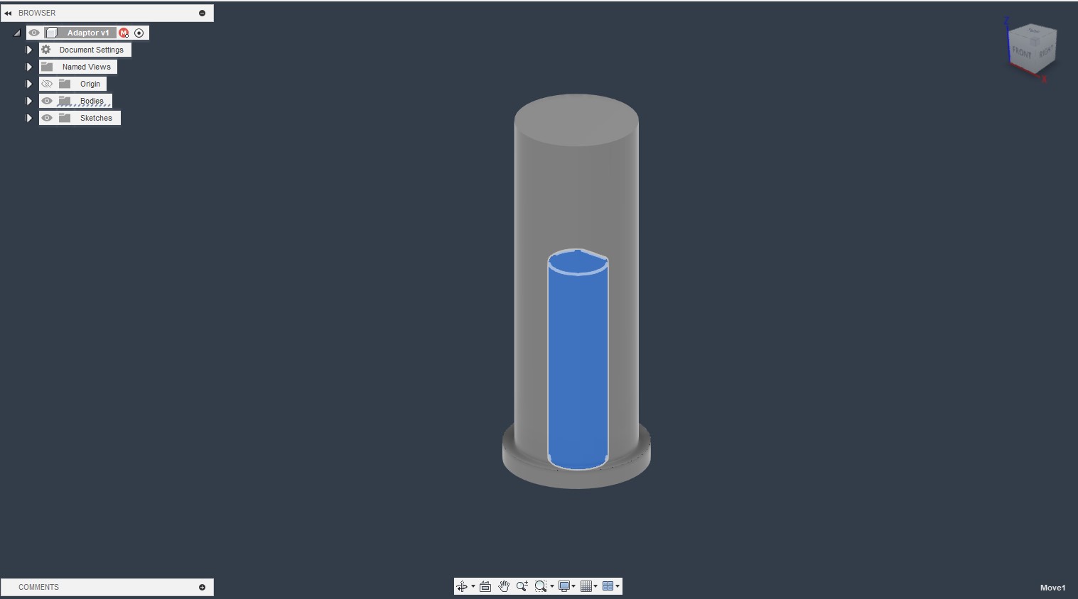
I then used the move tool to place the D shaft inside of the motor mount
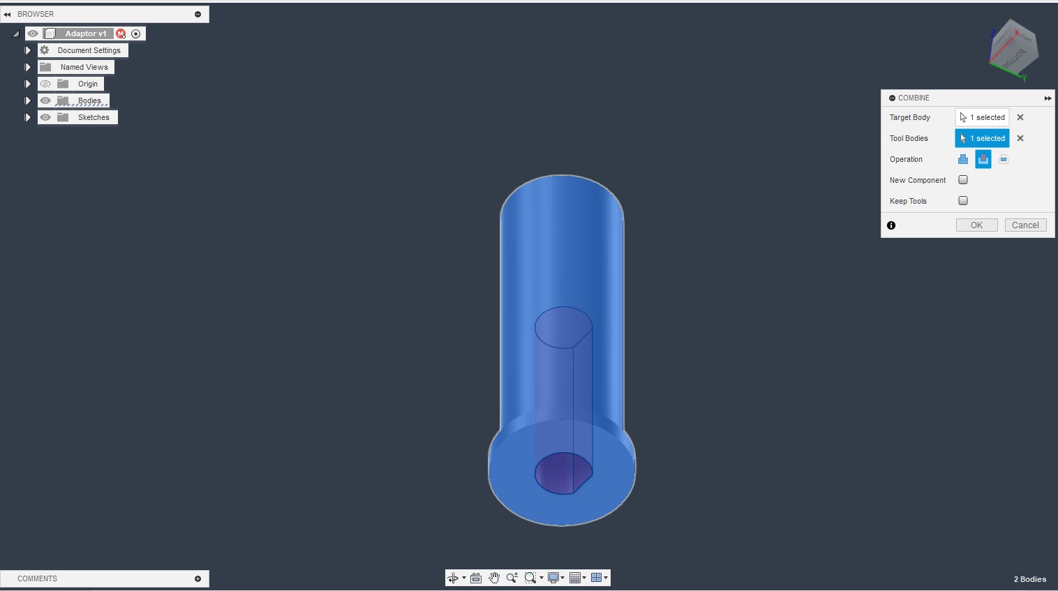
Finally, I used the combine tool to cut the D shaft into the motor body.
Wheel mounts- Printing
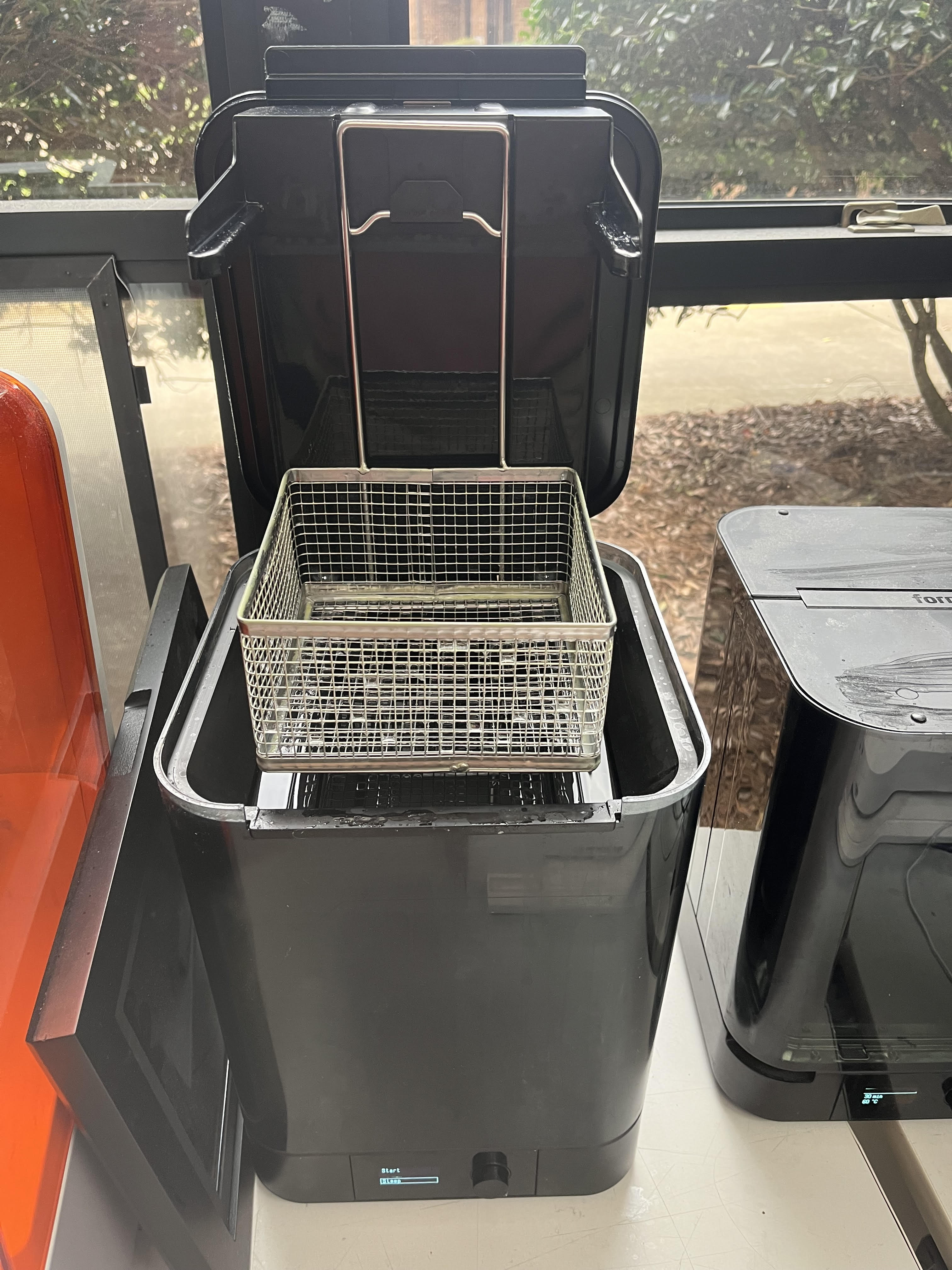
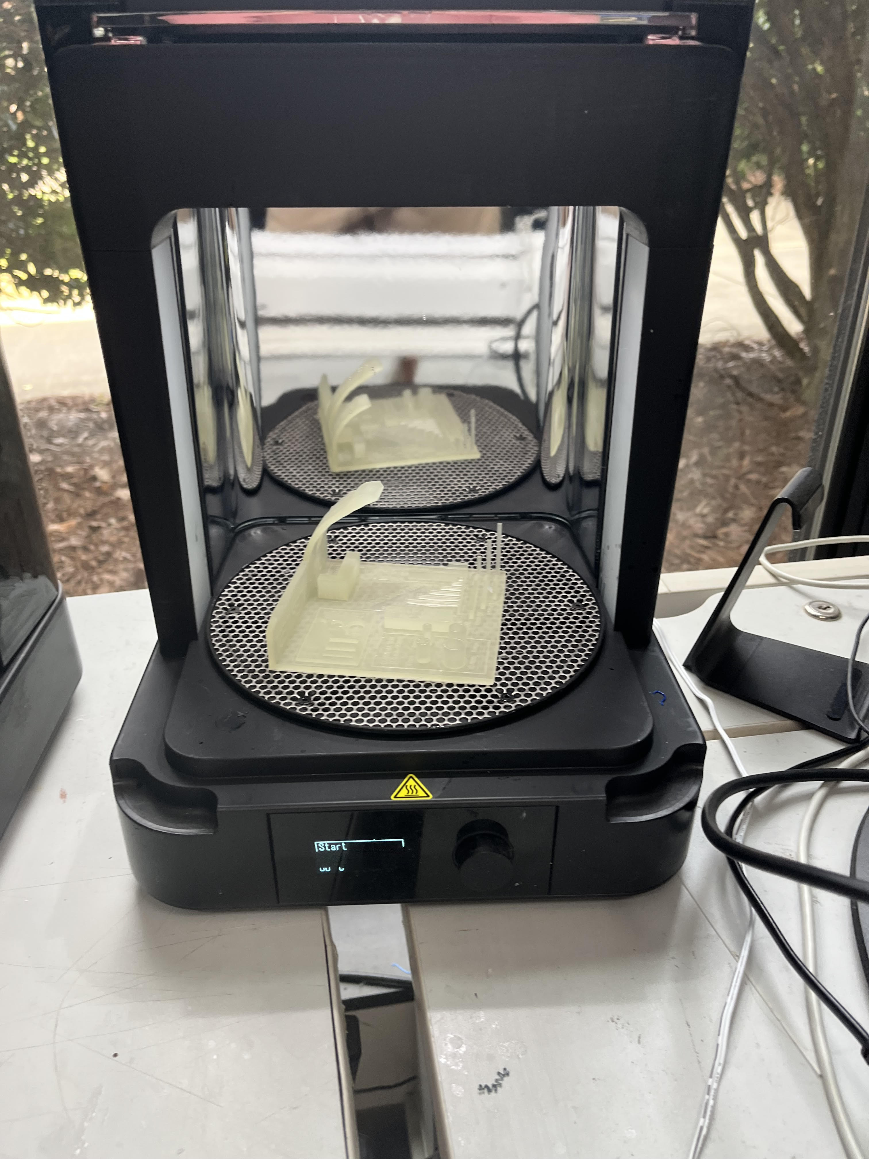
To print the wheel mounts I used a Formlabs 3 SLA printer, since a high compression strain will be resting on the mounts, and I need the tolerances to be percise. SLA printers use layers of resin hardened by a UV light, which allows areas to be targeted, and there’s no “Ironing effect”, like from a traditional printer.
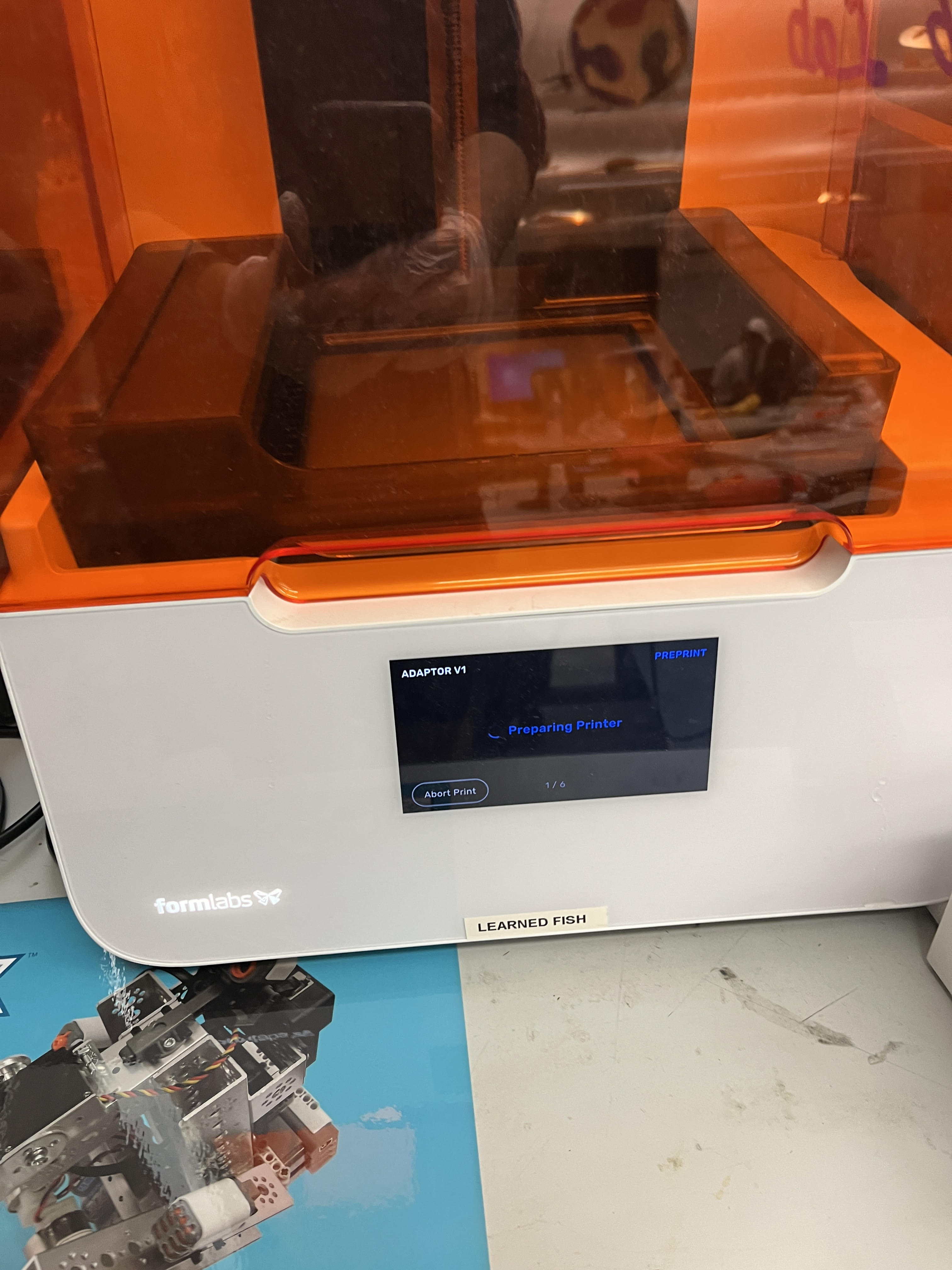
A little more preperation has to go into setting the printer up, I had to go to the printer and make sure the cartridge of resin was full, and then use the touchscreen to prepare the printer.
To slice the wheel mounts, I’m using Formlab’s preform software. First, I imported my file using the import button, and added my 3mf file.
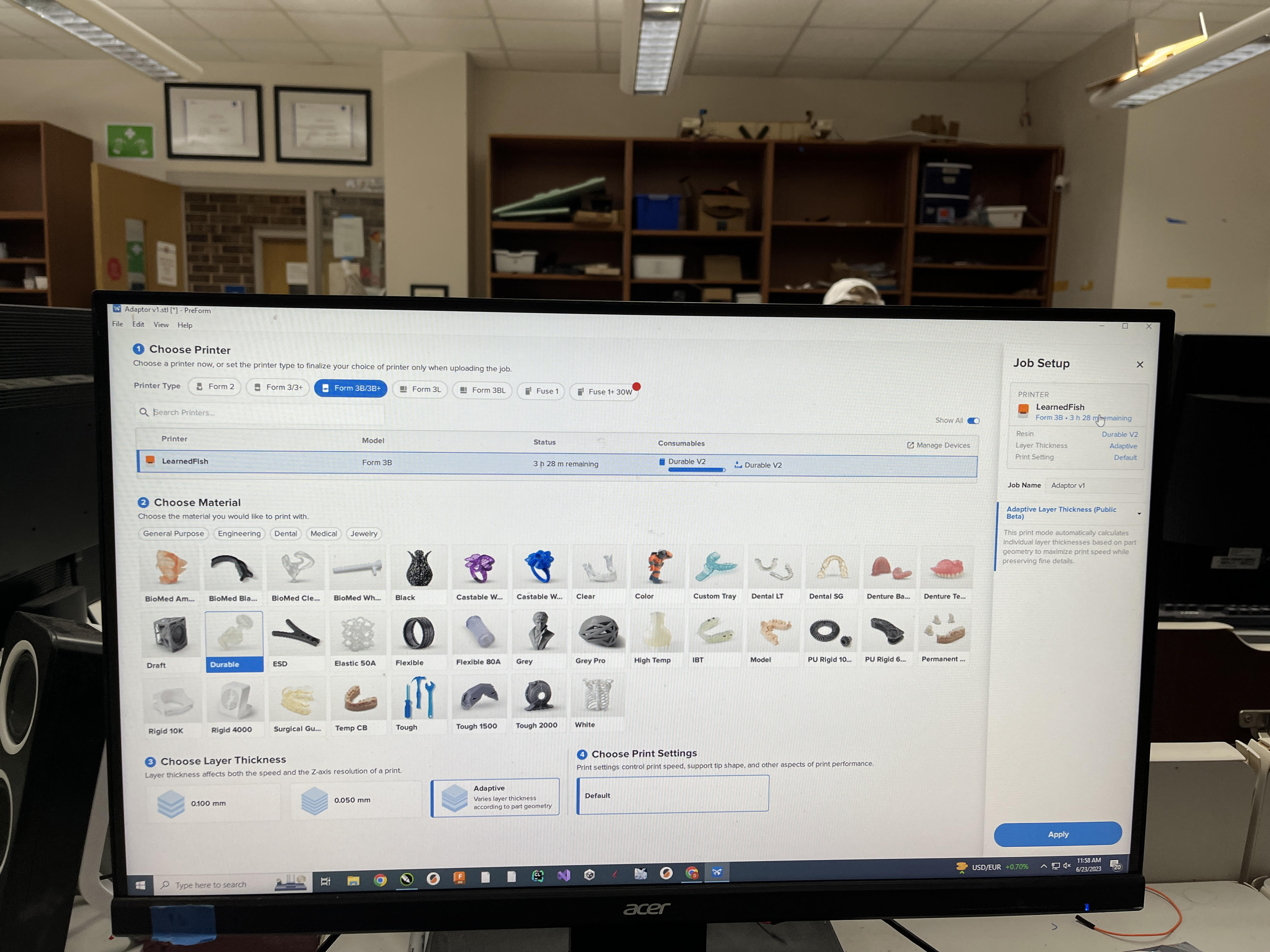
The first thing I did was select what printer and what material I was using on this page.
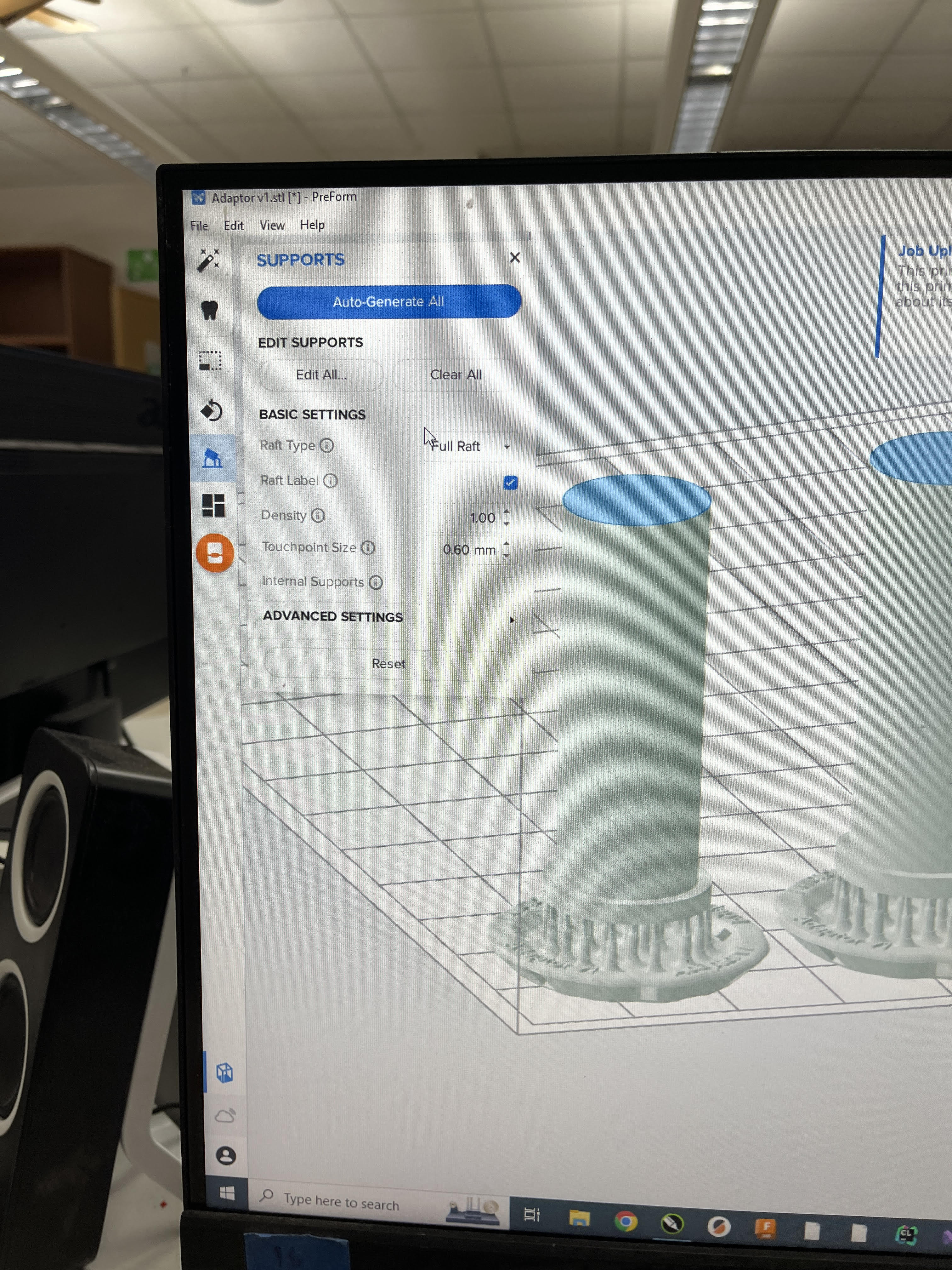
Then, it was similar to a normal slicer. I first created a raft to make it easier to remover the parts.
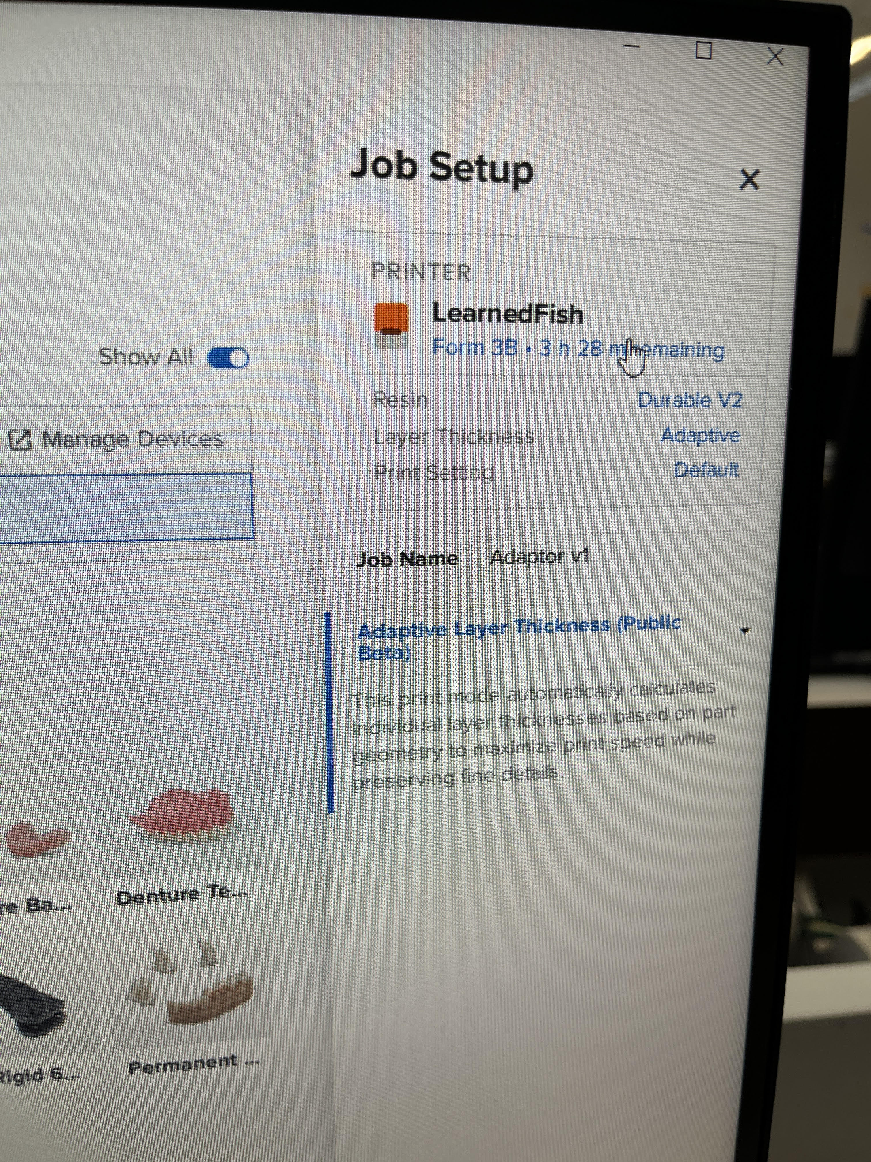
Then, I selected the thickness I wanted to use, I chose to use the variable layer thickness setting as it saved the most time.
After printing, I had to wash and dry my part. The washer removes any excess resin from the outside of the print. The drier cures the resin and solidifies it, I didn’t get a picture of my part in the drier, but here is an example part.
Wheel Mounts
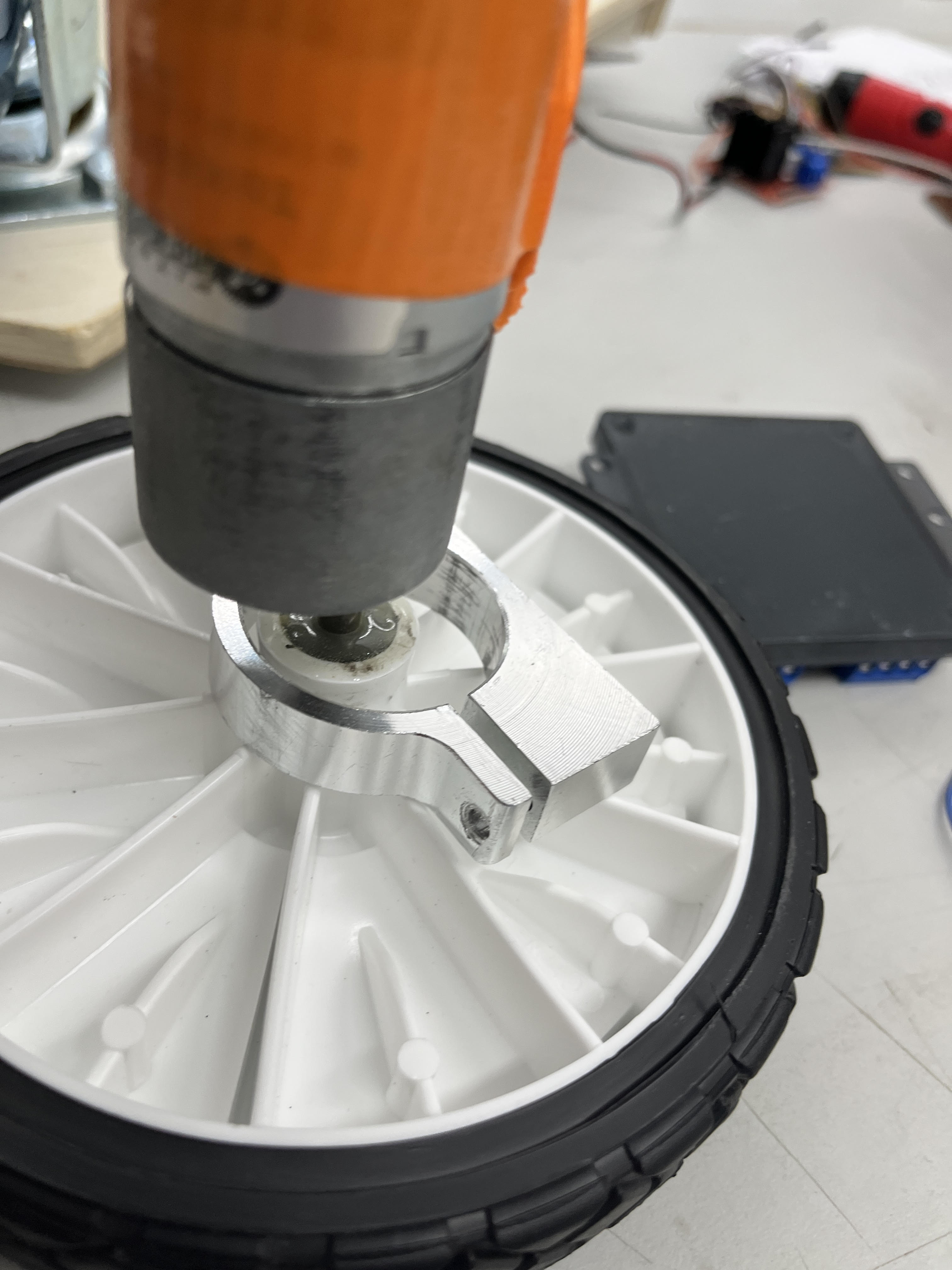
To assemble the wheel mount to the wheel, I inserted some epoxy into the D mount hole as well as on the edge of the wheel to keep it in place
First test and changes made
For my first test I used my laptop as a power bank, as I forgot a portable charger to use as power for the seeed. The caster wheel was also way too large, so I bought a smaller one.
Second Motor Mounts
I noticed that when I placed the wagon on the ground it had some give at the wheels. To fix this I made another set of motor mounts. Tetrix includes Cad Files on their website, so I printed a set and installed them on the back end of the motors, using the same drilling process I did before.
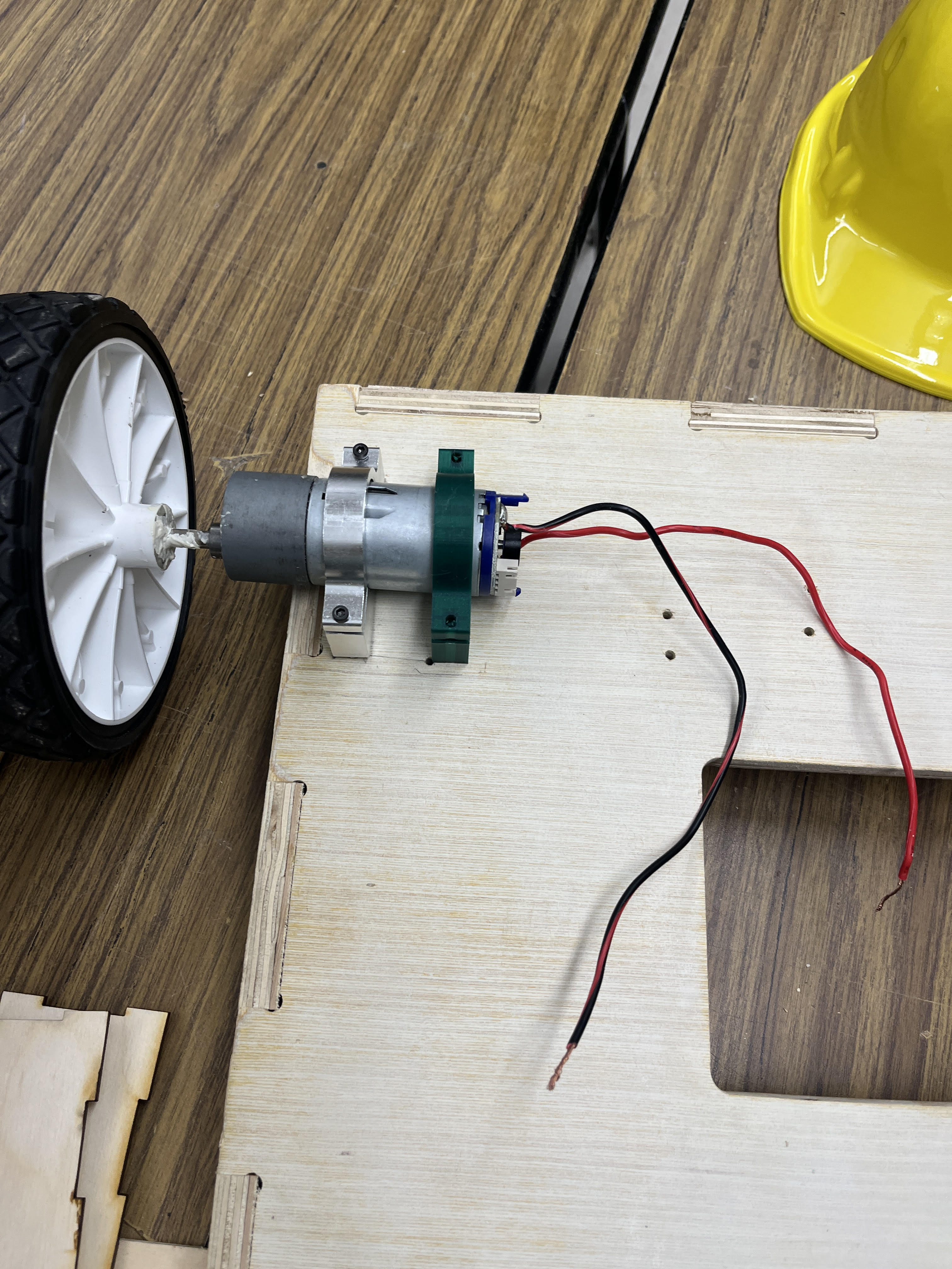
My 2nd set of motor mounts.
2nd Test
After this, the wagon drove much straigher because of the 2nd set of mounts, and it wasn’t tilted in any direction. I also had a portable charger to supply power to the seeed.
System Integration
Now that I have the wagon working, I need to integrate and package the product.
Laser Cut box
I used makercase to create plans for a tab cut box the length of the wagon to store my electronics. After assembling the box with hot glue, I put velcro tape on the bottom of the box and the bottom of the wagon body to hold it in place.
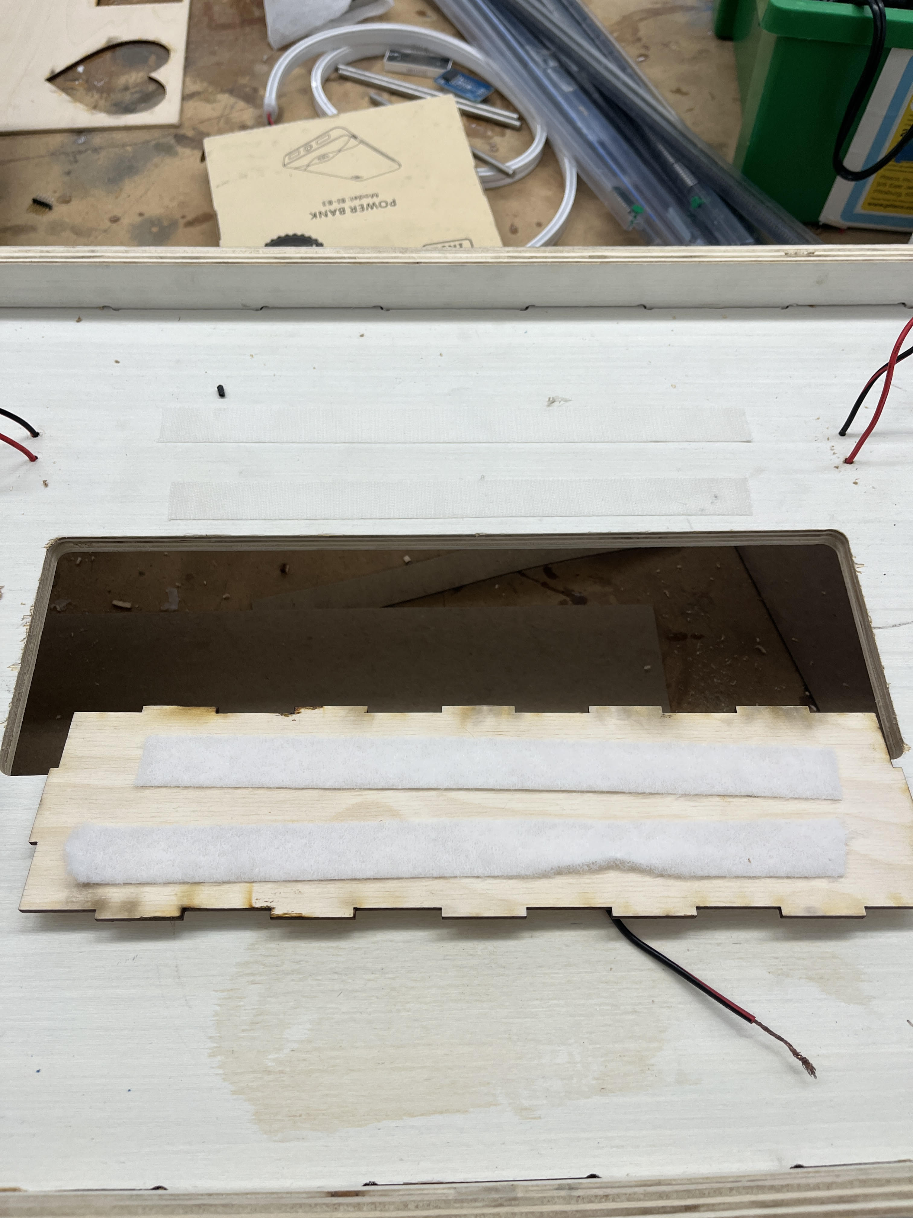
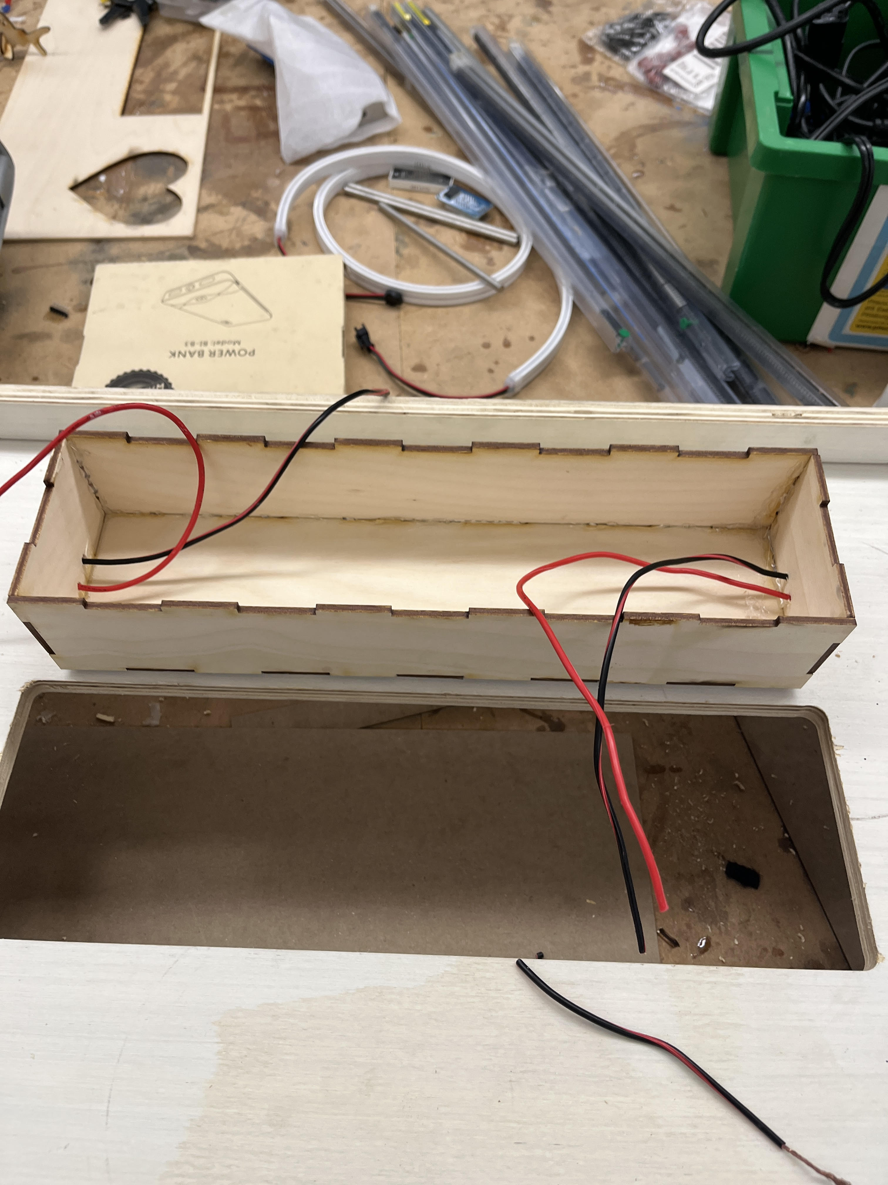
I then drilled holes through the bottom of the wagon body and the sides of the box for the motor wires.
Wiring
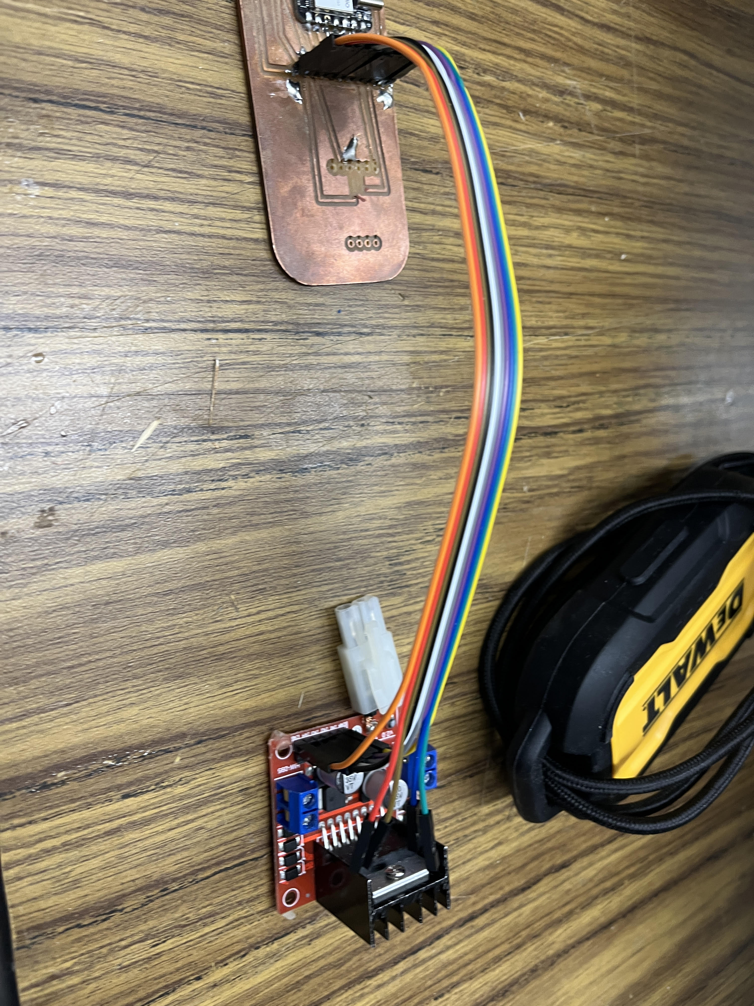
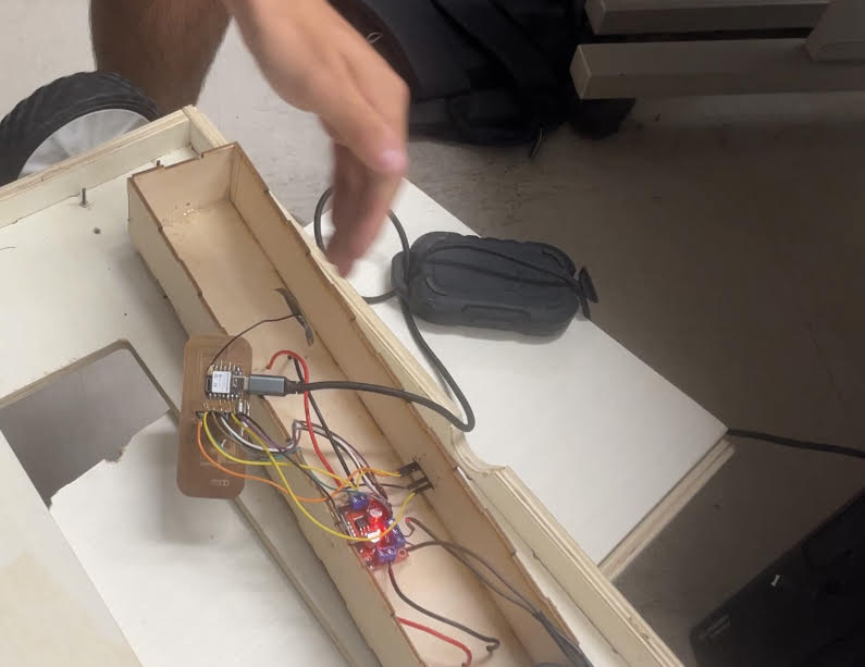
I then took a ribboned jumper cable to add a connection between the motor driver and my board, and split off the wires for the Time of flight sensor. I also soldered a Tamiya connector to my board, as it is the native connector for the 12v tetrix battery.
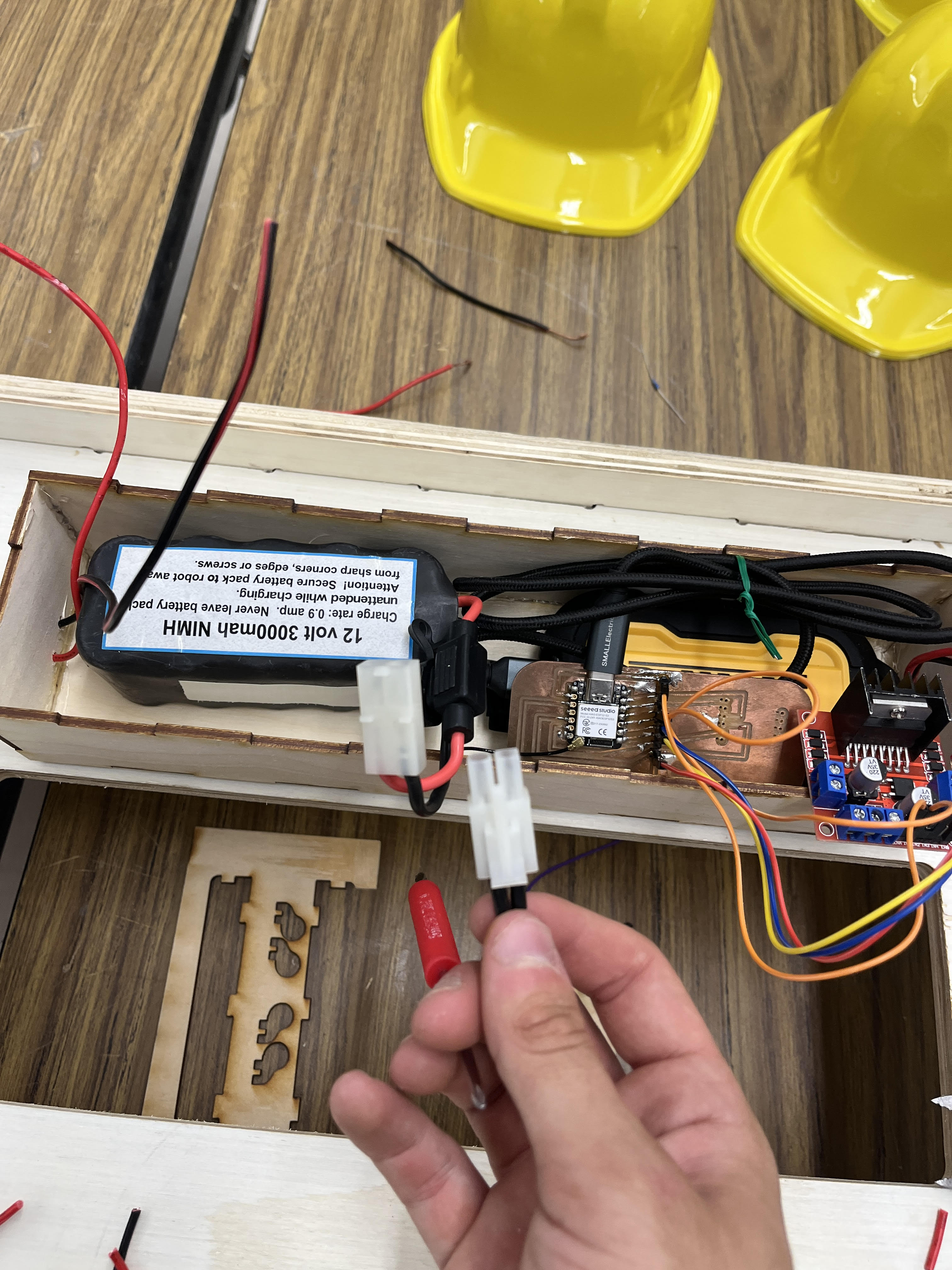
Another view of the Tamiya connector + my electronics before the ribbon cable. !
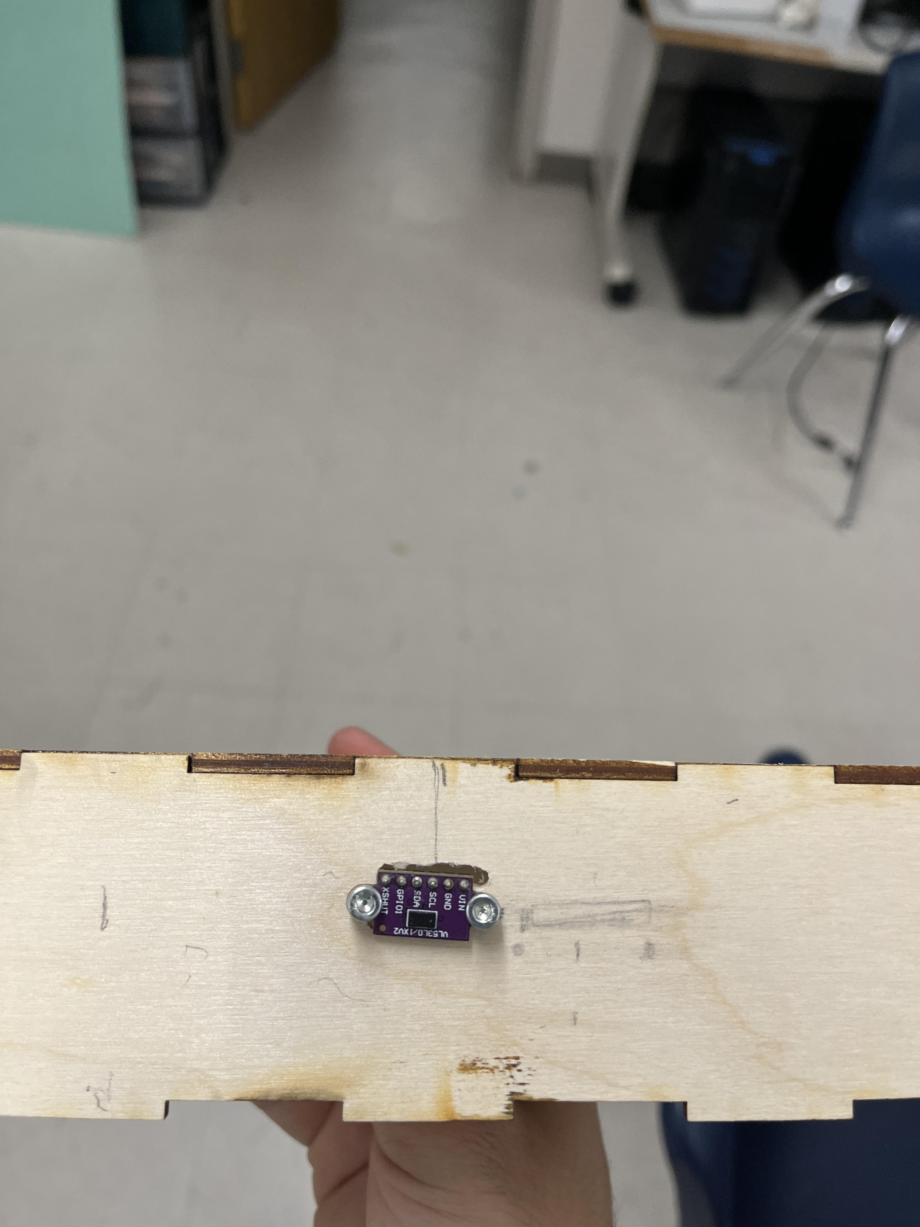
Then, I mounted the time of flight sensor. The PCB I was using had built in M2 Mount points, so all I had to do was drill holes, and then use M2 bolts and nuts to attatch the sensor.
First drive with integrated packaging.
Integrating The seeed Box.
The only problem I encoutered before integrating with the seeed box was the Time of flight sensor hitting the front wall of the wagon. In order to fix this, I first used a spade bit to cut down a hole, and then sanded the edges to create a notch in the front of the wagon.
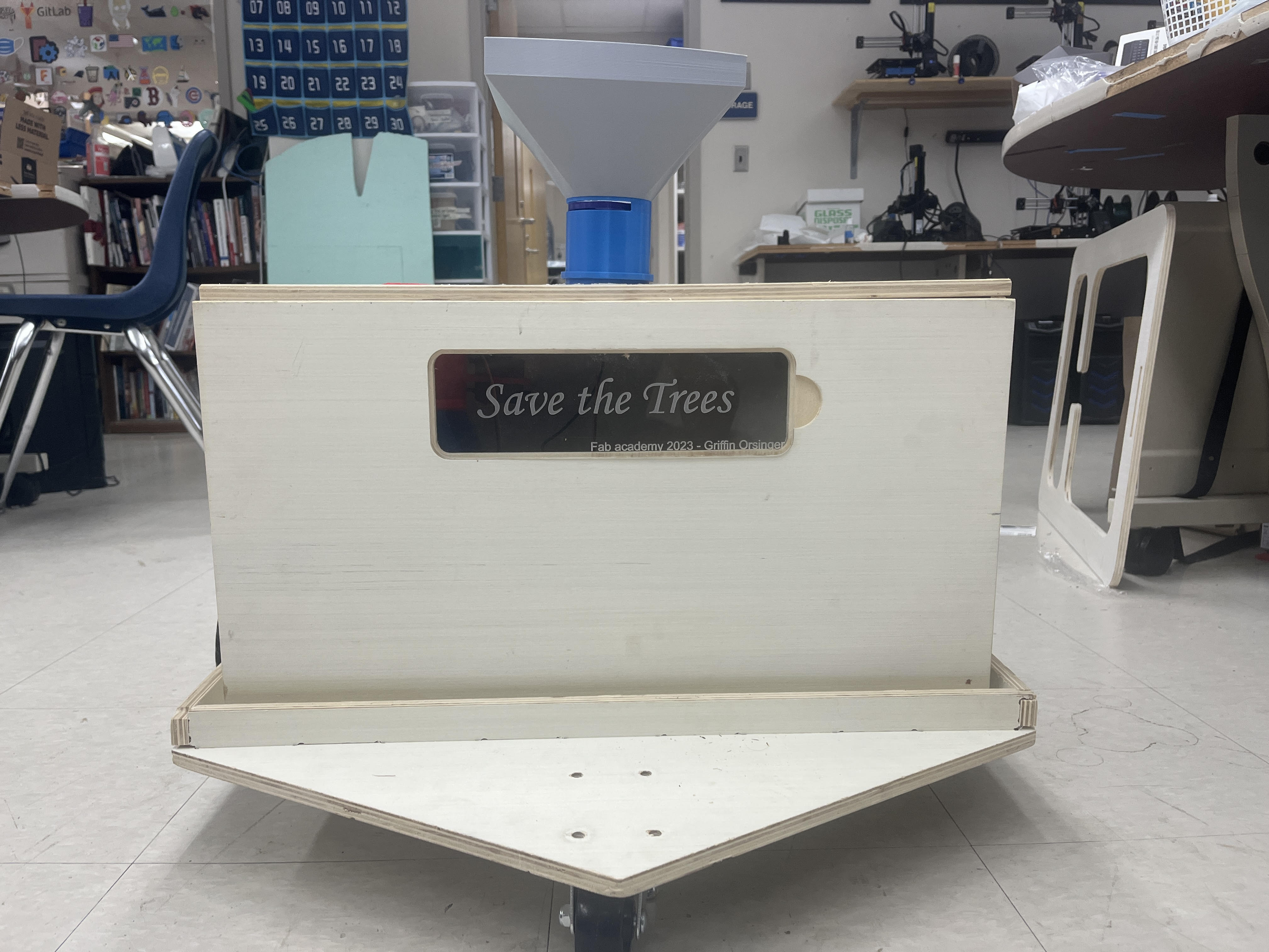
After that, I placed the seed box on top of the wagon, which fit snug into the bed.
The final product
File Downloads, Creative Commons License, Final Slide and Video website links
Click Here to download a zip folder of all my files: including CAD/CAM files for my boards and the wagon, CAD files for 3d printed pieces, SVG file of my box, and the file for my code.
The Fab Wagon by Merritt Backerman is licensed under CC BY-SA 4.0![]()
![]()
![]()
Reflection
The Fab Wagon was a difficult project for multiple reasons, partially because there were so many different ideas that I wanted to try and integrate, and partially because it was complex in nature. I’ve never built a moving project before, so I had to learn from scratch the mechanical, electrical, and project management considerations that come with that. Mechanically, I learned how to create balance in the Fab Wagon, making sure that weight was distributed evenly and it wasn’t over or underpowered. Electrically, I learned how to use motors and motor drivers to create a differential drive system. For project management, I learned how to create a stable housing for the electronics and other components of the wagon. Overall, I’m glad that I tried to integrate the ideas that didn’t work too, such as PID control, which has since made me interested further in control theory, and is something I plan to implement when continuing the project. After the beginning of my project and the failure of PID control, the biggest question I had was how to control the wagon in terms of inputs. I experimented with GPS, ToF, and Bluetooth interfacing on a device, but I ended up picking a game controller. The game controller made using the wagon intuitve. All it took was a few seconds to explain the controls to my peers and they were able to drive the wagon exactly how and where they wanted to.
Evaluation Criteria
My initial evaluation Criteria were the following:
- The wagon must follow a designated person and only that person at a resonable distance
- The wagon must avoid other objects
- The wagon must integrate with the seed planting system
These criteria were created when I was still experimenting with different control methods, which is reflected in the first evaluation criteria. However, with human input it could still be possible to perform. The other 2 criteria were met, criteria 2 by the automatic stop system with the VL53L0x, and criteria 3 by the fitment of the seeed box on the wagon.
Implications: now and future
Right now the Fab Wagon could be used exactly as intended when integrated with the seed box. A human would be able to control the seed box while in their line of sight to drop seeds in a specific pattern. In the future, I’d want this process to be more automated by not just following a person like my original idea, but able to drive with no human. I’d acheive this by integrating GPS along with a more advanced object detection system, and more percise steering could be acheived via PID, which I have already worked on.