Week 7: Computer-Controlled Machining
In our lab, we have two ShopBot milling machines, a ShopBot PRSalpha, and a ShopBot Desktop MAX. This week our group used our lab Desktop MAX, which will be referred to as the “small” cnc in comparison to the “large” cnc that is the shopbot alpha.
CNC Safety
Using the CNC machines can be very dangerous, in our lab, we always have eye and ear protection on while milling. Before cutting I make sure that the toolpath works, I do this by doing an offset cut by doing a 3D offset in the Shopbot software. Another safety feature is making sure the key is always unplugged from the machine when not milling, especially when changing bits.
Designing The Wavy Whale
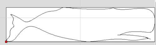
I chose to design and cut a whale that I saw at the Chatham art in the Park show over the summer. I started designing in Fusion 360 by importing an image of a sperm whale I found on Google. Then I did the fit point spline around the outline of the whale and then I extruded it by 1 in. As an added touch I changed the appearance of the design to cherry wood using the appearance tool.
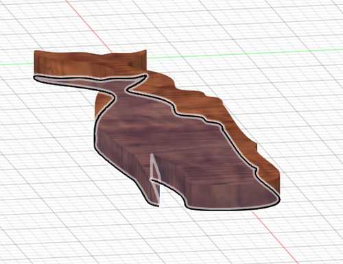
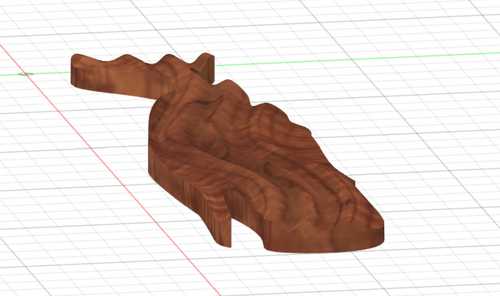
Next, I created a wavy design on the right plane by making a fit-point spline on one side of the whale. Next, I created another fit point spline on a new sketch on the top of the whale. I made this way to add an ocean wave-type design when I used the sweep tool in cut mode to cut away the extra wood.
Machining workspace for the Wavy Whale
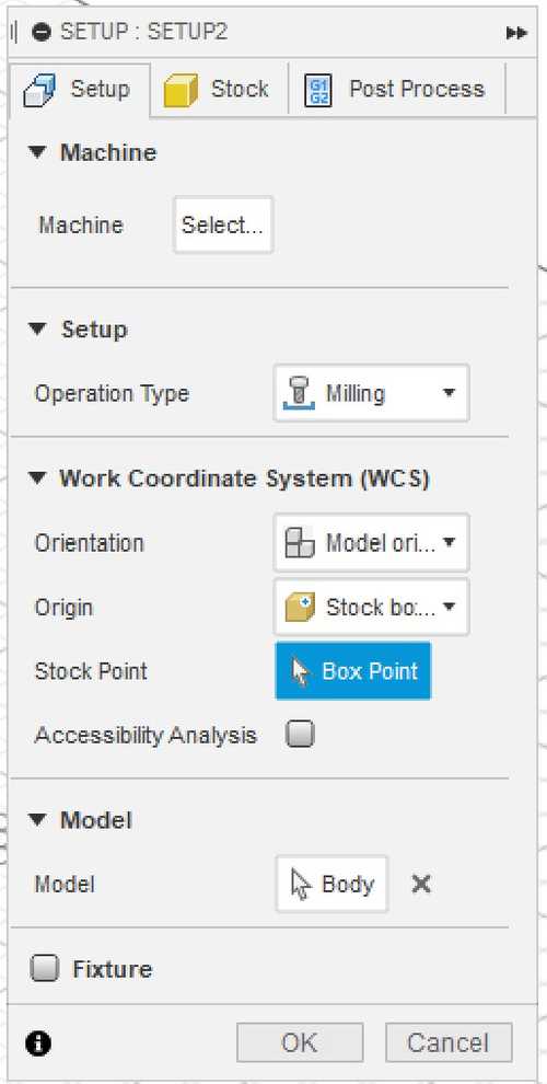
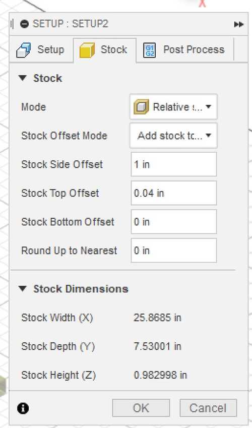
I decided to try learning the machining workspace of Fusion 360. I started by getting a short lesson from Garrett Nelson who visited our lab this week to show some machining techniques. Since at the time I was in a crunch for time, he was only able to show me the basics of creating toolpaths. For further learning, such as setting up my stock and other information, I watched these) tutorials by product design online and started watching these. They were really helpful with the rest of the design software. I started by downloading the amana tools library and the post processing library for my lab’s big shopbot. The first step in using the workspace is setting up the print, here are the settings I used:
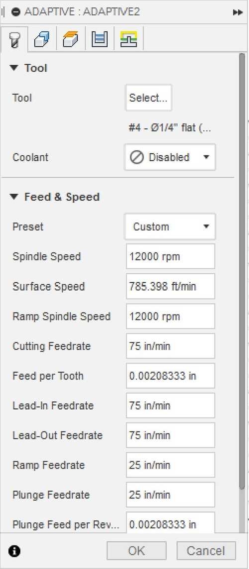
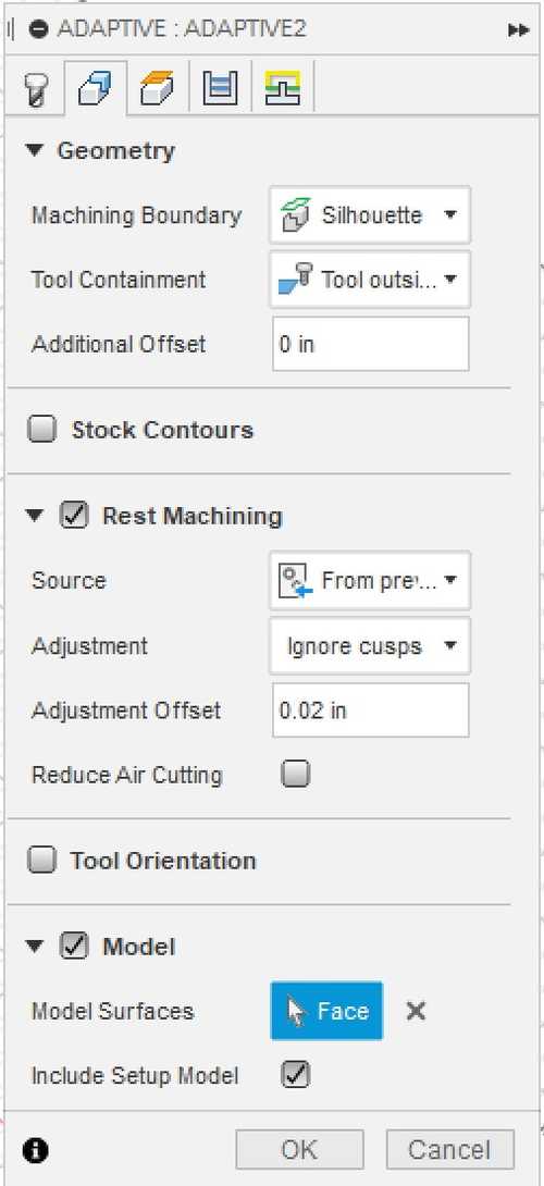
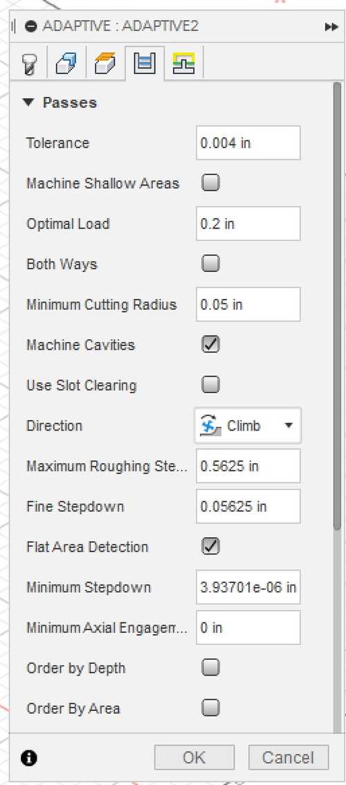
Next, I made my first toolpath, a 3D adaptive toolpath to do a roughing run of the waves in the whale. I chose these settings to maximize speed while maintaining the highest quality.
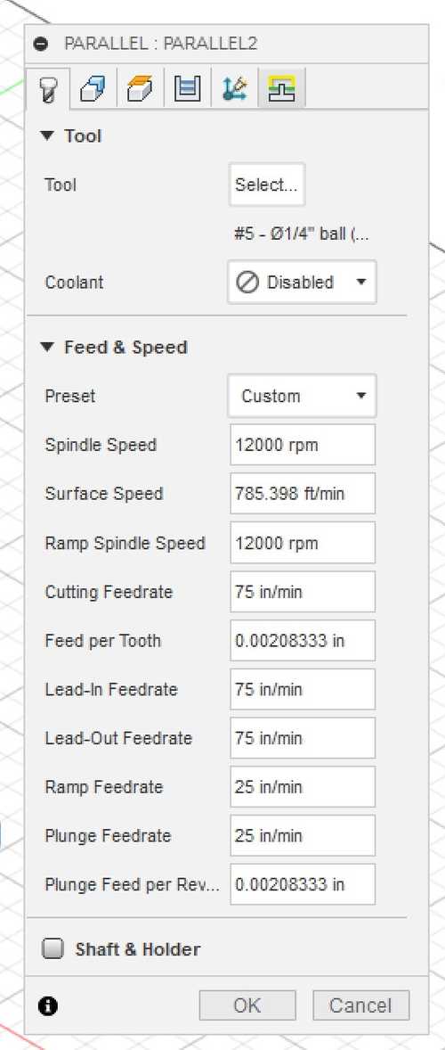
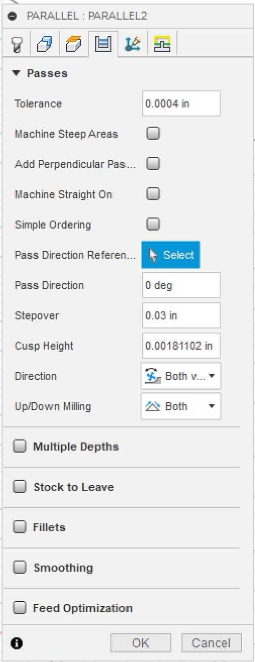
To create a smooth surface, I will do a parallel toolpath to smooth the waves. Here are my settings:
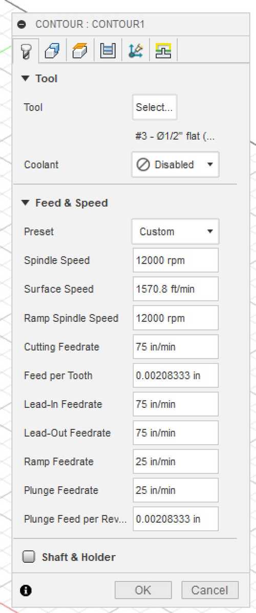
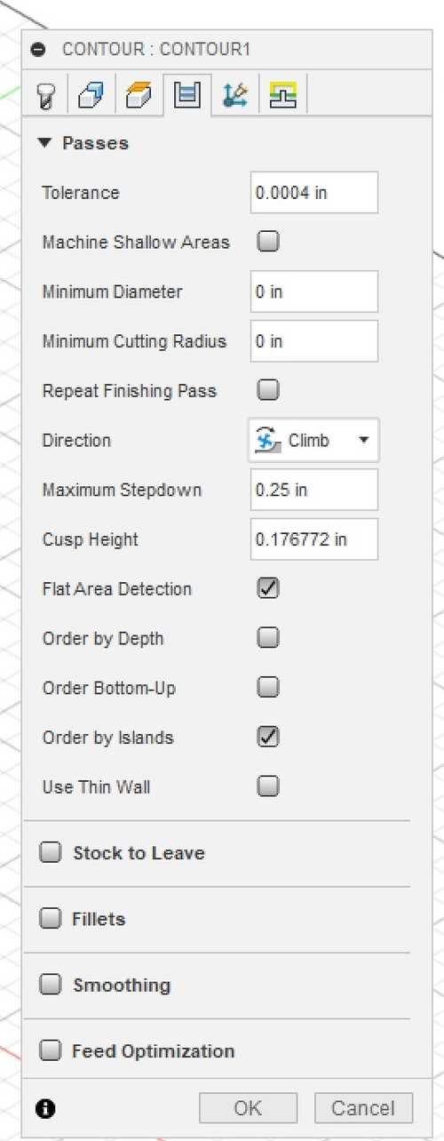
The final toolpath I made was a contour to cut out my whale. I chose these settings:
Cutting the Wavy Whale
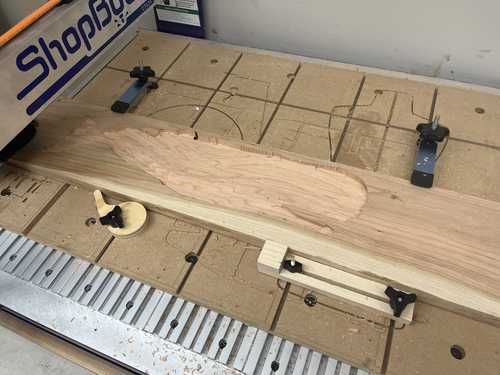
When cutting the wavy whale I had a lot of problems. Some of these include securing the whale, the bit not cutting deep enough, and the bit cutting too much. To start the cut I initially did an air cut to test the toolpath and it seemed to work perfectly. Then I cut the toolpath with no offset and the bit drove straight down into the wood too fast and too far and the wood started burning, creating a charred hole in the side of the wood.
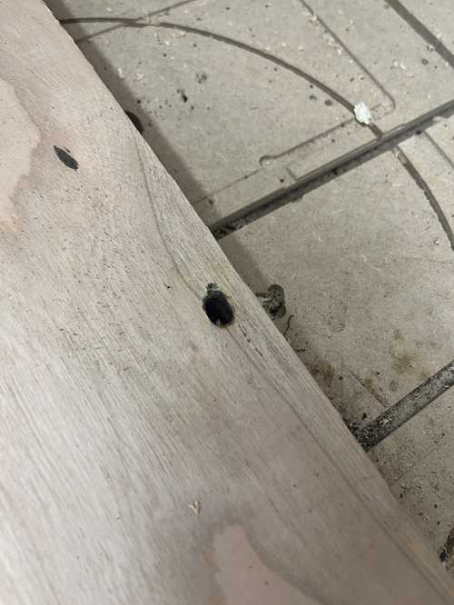
I have no idea why the cut did this and in my toolpath simulation in Fusion 360, it also did not drive down into the wood. I tried to fix it by starting the cut again with a 2D offset and it worked, but the only issue I ran into was that I had to move the spindle to 0,0 or the cut would be offset by where the spindle is. I started the cut and after some time, the whale was roughly engraved.
The next step I took was doing a finishing pass with a 1/4 in round end mill. I took the same process, starting at 0,0 and starting the cut with a 2D offset. I have no idea why but the bit was not getting close enough to the wood, it was about a millimeter higher than it needed to be and was not cutting into the wood. To fix this I tried zeroing the z-axis deeper than the actual zero to create a z offset. I went into a divot in the wood, about .15 inches, and used the command ZZ to zero the z-axis. Then I raised the axis a few inches to clear the wood and returned to 0,0. Then I started a new cut with a 2D offset and in the beginning, it was cutting almost perfectly. It was not cutting quite deep enough into the wood so I thought that I would just lower the zero a bit more and do a second pass. However about halfway through the cut, when traveling across the whale to cut on the left side, it cut a deep line across the middle of the whale. This surprised me because it was working fine for the first couple of minutes until it made that line.
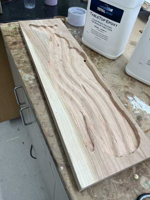
At this moment I decided that I would trim down the wood to a smaller size. Sand the inside of the whale cutout and try to salvage my work by filling it with resin. I will finish the resin work wildcard week because I ran out of time.
Designing the Flat Whale
To design the flat whale I started by taking the outline I made for the wavy whale and copying it onto a new document. On that document, I rated the whale to be about 55 inches long and about 15 inches tall. Next, I extruded that shape by .466 inches. I chose this thickness because it was the thickness of the wood I was using and would provide an accurate representation of the whale in Fusion 360. Next, I exported the file as a dxf.
CAM in Aspire
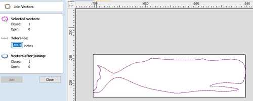
The next step I took was opening the aspire software on my computer and importing a new vector.
Then I deleted what seemed to be extra lines and used the join closed vectors tool to ensure that my cutting path was clean.
At this moment I realized that I could fit on the same board as my classmates, Griffin and Adam, and decided to do all this over again in their group file. After redoing all the steps above, I managed my material and made sure that z height was from the machine bed, not from the material surface.
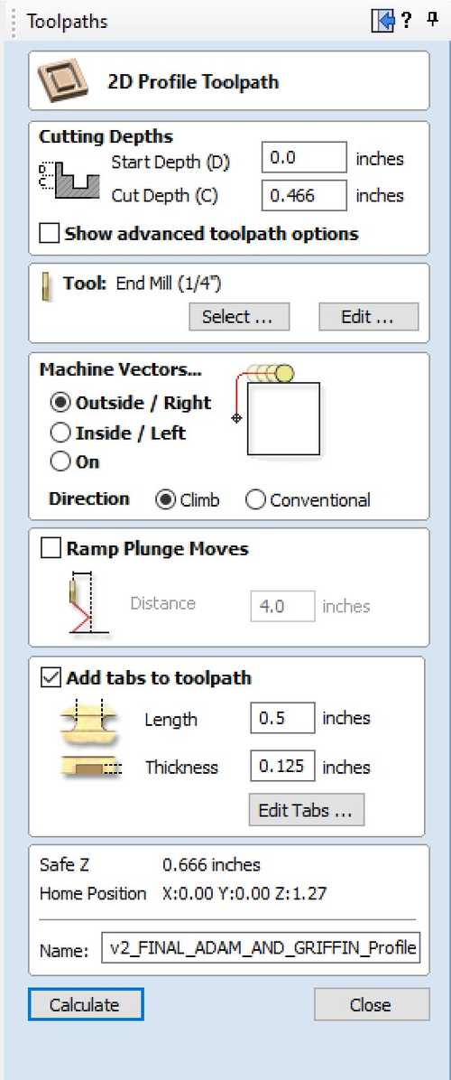
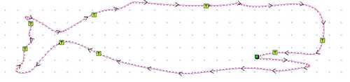
To cut, I made a profile cut with a 1/4 in end mill bit. I also added tabs to keep the whale in place after it cut through and I chose these assorted spots.
Next, I sent the file over to the cnc using the Shopbot software.
Cutting the Flat Whale
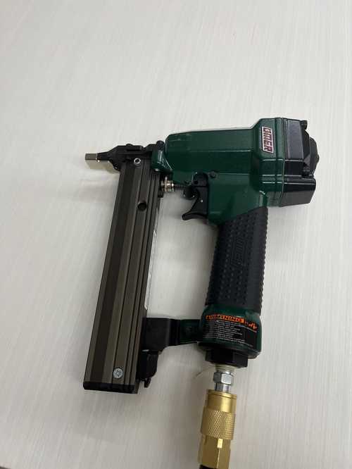
The first step I took in cutting the whale was preparing the wood. We chose a 1/2 in plywood that we measured at .466 inches and nailed it into the cnc table using a Brad nail gun. This would ensure that the wood would not move during the cut as well as with ease of removing the print from the bed.
Next, I followed this workflow:
Shopbot Cutting using Aspire/ VCarve Toolpath
Last updated March 13, 2022
Shopbot Machine
Put on eye and ear protection
Close the doors
Check to see that the machine has been warmed up
Check to see bit is not loose
Measure the thickness of the material that you plan to cut.
Raise the Z-axis so the bit won’t drag on the table (no higher than 4 inches)
Use the proximity switch to set Calibrate. (C3 keyboard command)
Calibrate Z AXIS on the table. (C2 keyboard command)
Raise Z AXIS 4 inches using the JZ 4 command
Attach material to the table using screws
Raise Z AXIS 4 inches using the JZ 4 command
Set new X and Y Origins for your design
Raise the Z-axis so the bit won’t drag on the table
Using keyboard jog to the appropriate X and Y location. (J2 X,Y)
Using keyboard to zero the appropriate X and Y Location. (Z2)
You set origin.
Select Cut
Start up Aspire and VCarve software
Open your file
Select objects you wish to cut
Select Toolpath
Pin Toolpath
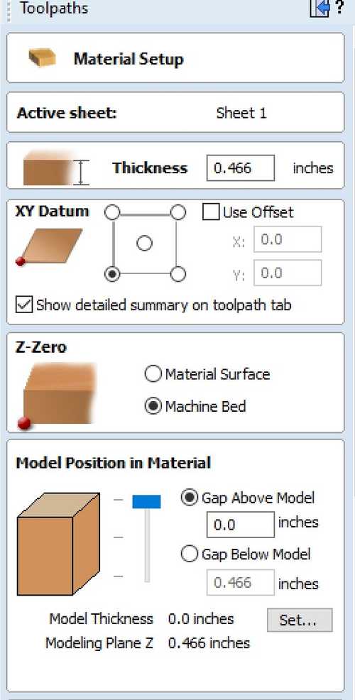
Click on material setup
Check Z - zero is on the bed, NOT the board
Enter the thickness of the material *
Model position material should be the same thickness as the material.
Click OK.
Go to TOOL PATH OPERATIONS
Select 2D Profile Toolpath
Under cutting depth, select the cut depth of the material (CLS tools).
Select the proper tool -CLS down bit ¼
Click add tabs and add tabs
Hit CALCULATE.
Preview toolpath
Click on CLOSE
Select SAVE TOOL PATH and save the file in a shopbot format
Start ShopBot Command Console
Conduct air cut
Select FILE-LOAD
Load the appropriate file
We Select 1 3-D offset
Press ENTER
Turn on the spindle by pressing the big GREEN Button
You should hear a “SOUND” of the spindle now turning
Press ok
After checking that everything is good; press space bar
Select quit
Return to origin (J2 0,0)
Perform cut
Select FILE-LOAD
Load the appropriate file
Select no offset rather than 1 3-D offset
Press enter
Turn on the spindle by pressing the GREEN Button
You should hear a “SOUND”
Turn on the vacuum
Press enter again to start cut
Cut is done
Turn off vacuum (which is so loud you shouldn’t forget)
Use a hammer and chisel to remove tabs
Clean up after yourself
Get a broom and sweep
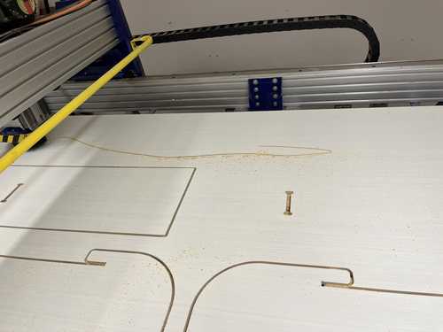
Here is the design in the middle of the cut
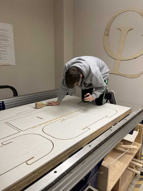
Here is Griffin helping chip off some of the tabs with a hammer and chisel.
Here is the finished product before sanding
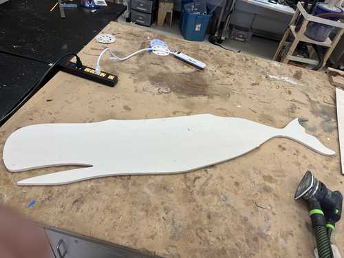
and after sanding

Stand For the Flat Whale
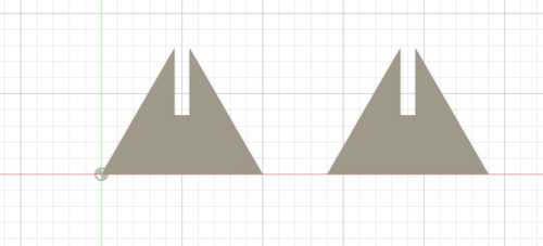
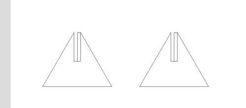
To try something new again, I made a stand for the whale using dogbone press-fit supports. It was a simple design in Fusion 360 with an equilateral triangle and a rectangle that was the thickness of my plywood, .466 inches. Here is the design.
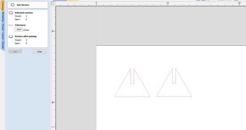
The next step I took was uploading the file into aspire, setting my material size as 34 x 15 x .466 inches, and making sure the z is from the machine bed, not from the material surface. When I opened the file in the drawing workspace, it had some extra lines not in my design.
To fix this I deleted them and used the close vector tool
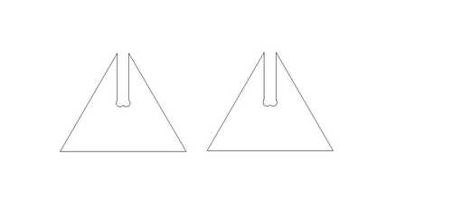
Then I added dogbones to the edges under the filet tool for the joint to work better.
Next, I created a new profile toolpath with a 1/4 inch flat end mill and set the feed rate at 250 in/min, the spindle speed at 18000 rpm, and the plunge rate at 20 in/min. Then I saved the toolpath.
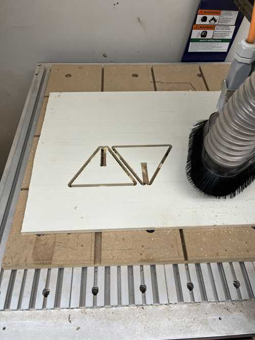
Milling on our labs small cnc
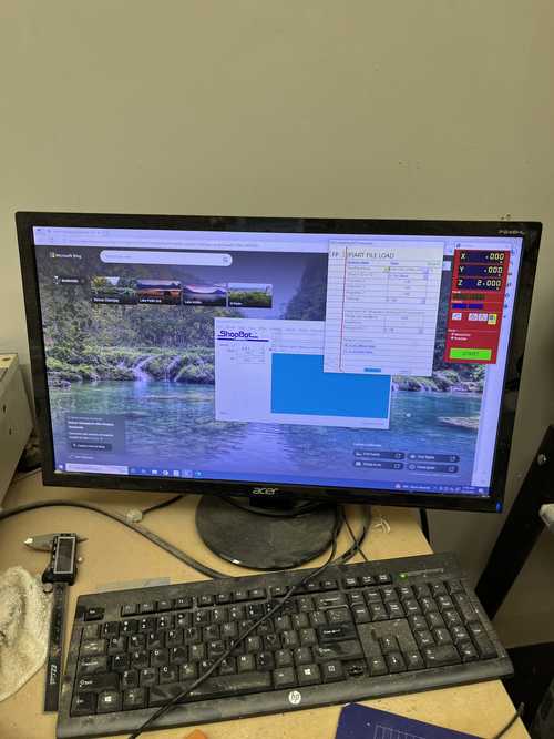
To see the setup, zeroing, and other basic processes see my group work. After doing the spindle warmup, and zeroing my axis on the bottom left of my workspace, I started by doing an aircut like in the group work. After that worked, I sent over the real cut and it worked perfectly.
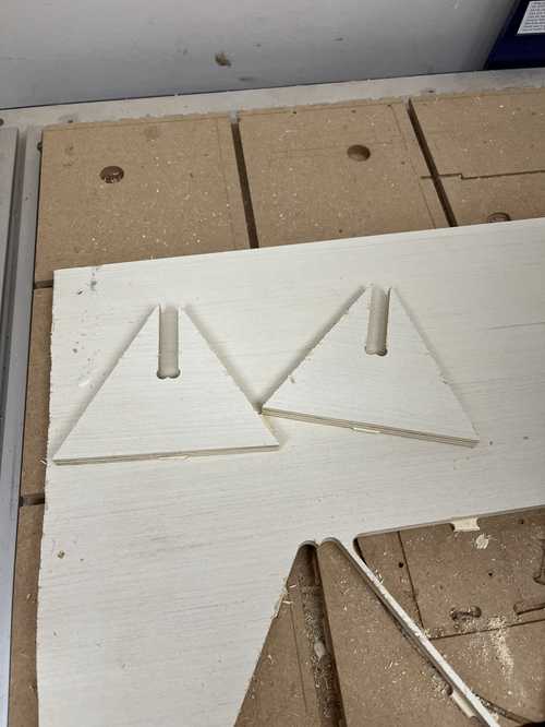
Results:
Post Processing
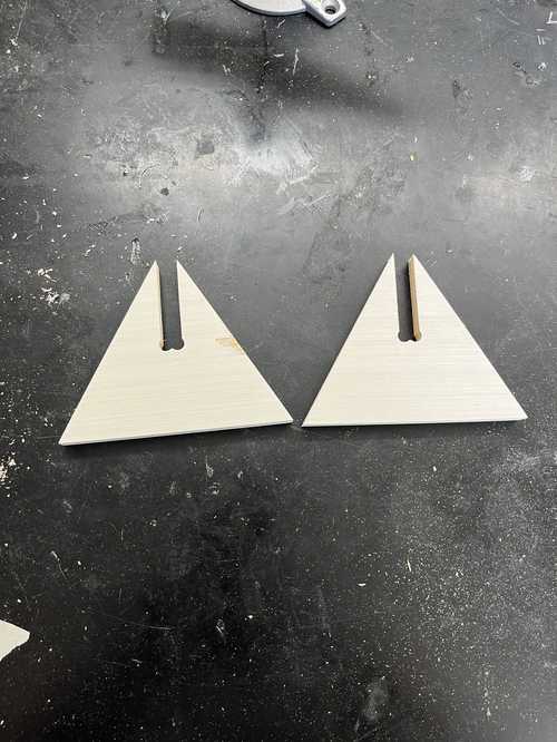
To post-process the stands, I sanded them on the sides with 60-grit sandpaper on a belt sander, and for the top and bottom, I used 120 with a hand sander.
Pre-sand:
Post-sand
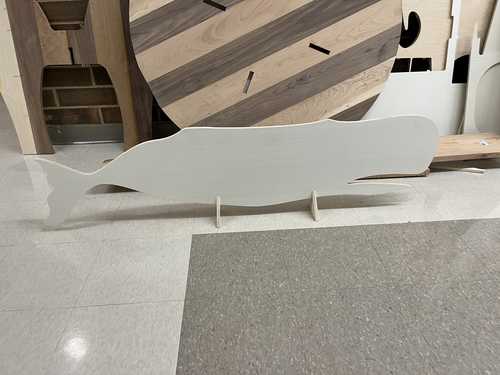
Then I fit them to the whale and they fit perfectly.
Group Work and Files
Find my files here and group work here. This week for group work I warmed up the spindle of the shopbot, set up the shopbot, and watched it cut. I also helped design the files by adding the feeds and speed for the bit we were using. Finally, I helped Stuart use the spindle runout speed by helping him set it up and spinning it while he read the values.