Week 6: Electronics Design
This week I will be designing a PCB board for my final project. I will use the Seeed XIAO RP2040, pinout and other useful info there, a joystick, and add compatibility to a neopixel array for my battleship game.
KiCad
In KiCad I designed my board for the output of my game, it features a 5 pinout for my joystick, a 3 pinout for my neopixels, and an extra 3 pinout with 2 digital outputs and a group for other uses. Here is how I made it. My initial learning came from the tutorials at tech explorations.
KiCad Schematic
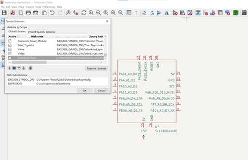
The first step I took was installing the Seed XIAO RP2040 library to work with my design. You can find the library here. First make a new project followed by opening the schematic editor. To install the library I went to the Preferences menu then Manage symbol libraries then I clicked on the folder logo and added the library. Next, I used the add a new symbol to add the seeeduino.
next, I added 2 3 pinouts, and 5 pinouts and connected them where needed with the wire tools.
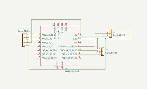
This concludes the schematic editing.
KiCad PCB Editing
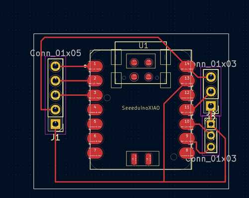
After opening the PCB editor, the first step I took was updating the PCB from the schematic editor by using the update PCB from the schematic button on the top bar (it looks like the schematic thumbnail and the PCB thumbnail cut by a diagonal line). This moves the components from the schematic to the PCB. This arranges them similarly to that of the schematic. to fix this I moved the components around to the approximate location where I would want them. Then I started to make the tracks by running them to the right pinout while keeping the clearance needed. After making the tracks to the right size, I switched to the edge cuts layer and made a rectangle around the design, this would be the size of the chip.
Finally, I used the plot command and plotted the design, resulting in my Gerber files.
Eagle
I also decided to use Fusion 360/Eagle CAD to design my board. In another software. I learned Eagle from the tutorials on YouTube here. After following these tutorials, I made my design in Eagle.
Eagle Schematic
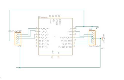
The first step I took was making a new electronics design from the file dropdown menu. Next, I pressed the new schematic. From there I pressed the add library button and added the seeed xiao rp2040 library to my design and ensured it was selected. Next, I double-clicked on the seeed schematic, followed by placing it on my schematic where I found fit. Next, I searched in the add items menu for a pin-header 1x5, double clicked, and placed it on the left side of the rp2040, then a pin-header 1x6 and placed it on the right side of the rp2040. Then I used the net tool to connect the pins the the appropriate data, ground, and power pins on the rp2040. Here is my finished result
Eagle PCB
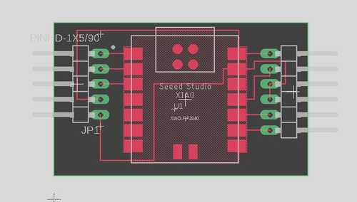
Now I switched over to the PCB editor by pressing on the tool on the top left of the software. Then I moved the pieces to where they would approximately go and made them as close as possible while still allowing room for tracks to go through. T then traced the electronic connections with tracks using the manual route tool and threaded some under the board along with some around the board. After that was done I chose the outline polygon and drew a rectangle around my board to shape the pcb. Here is the finished result.
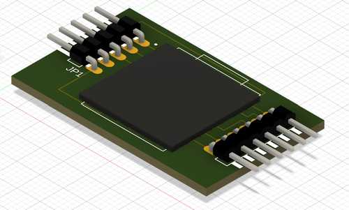
Then I pressed the view in the 3D editor to see my board in 3D, here is the result:
Finally, I exported the file as a brd file to be used to cut.
Comparing KiCad to Eagle
In terms of comparing the two software, I think Kicad has a simpler interface and is easier to learn. In terms of Eagle, I think that Eagle is a complicated electronic design software, but it has some benefits. It can integrate with Fusion 360-designed parts very easily, and you can keep your project in one software. This is a big plus overall with cost management and integration ease. Even with this said, I still think that KiCad is the better choice for me, because of how easy it is to learn and because it also has the bonus of being a free software.
Files and group work
Find the files here and group work here. I used the fade code example in Arduino to test the output of the seeed rp2040. I also set up, wired, and tested the oscilloscope while explaining how to use the voltage supply tab to the rest of my group.