Final Project: Sink the Submarine
Bill of Materials:
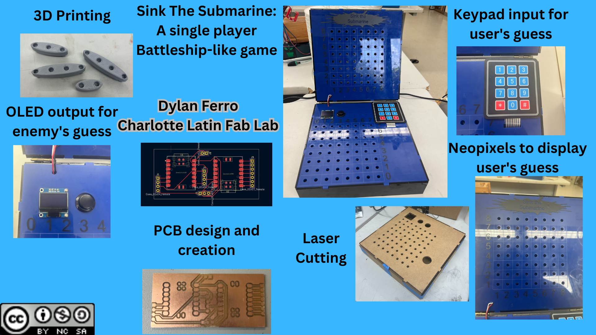
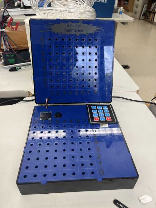
For my final project, I decided to make a single-player battleship-like game. Here is how I made it:
Coding Enemy Code
The first part of my project I decided to tackle was the coding of the program that would guess the ships of the player. I ended up changing the process about halfway through.
First Process: Pre-Made program
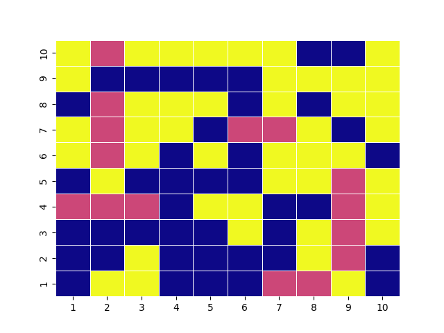
First, I started with a program made by Challenging Luck on YouTube, and it worked great, he used a probability simulator to create a heatmap and guided the program to guess the ship’s position. It would output the images as PNGs to be easily understood. Here is an example of that and the code.
import numpy as np
import random
import matplotlib.pyplot as plt
import seaborn as sns
from matplotlib import colors
from matplotlib import rcParams

opponentsBoard = np.zeros((10,10))
opponentsBoard[0:5,1] = 1
opponentsBoard[3,4:7] = 1
opponentsBoard[5:9,8] = 1
opponentsBoard[6,0:3] = 1
opponentsBoard[9,6:8] = 1
visitedBoard = np.zeros((10,10))
boardWithProbabilities = np.zeros((10,10))


def generatePlot(board, counter):
    name = "plot" + str(counter)
    cmap = 'plasma'

    ax = sns.heatmap(board, linewidth=0.5, cmap=cmap, cbar=False)
    plt.legend([],[], frameon=False)
    ax.set_xticklabels(['1','2','3','4','5','6','7','8','9','10'])
    ax.set_yticklabels(['10','9','8','7','6','5','4','3','2','1'])
    rcParams['figure.figsize'] = 11,11
    plt.savefig(name)

listOfAvailableMoves = []
for i in range(0,10):
    for j in range(0,10):
        listOfAvailableMoves.append(str(i)+str(j))


def randomGuessBot(opponentsBoard, visitedBoard, counter,successfulHits,listOfAvailableMoves):
    if successfulHits >=17:
        print("number of turns:" + str(counter), "number of hits:" + str(successfulHits))
        generatePlot(visitedBoard, counter)
        return(True)
    random_num = random.choice(listOfAvailableMoves)
    listOfAvailableMoves.remove(random_num)
    row = int(random_num[0])
    col = int(random_num[1])
    generatePlot(visitedBoard, counter)

    if opponentsBoard[row, col] == 1:
        successfulHits +=1
        visitedBoard[row, col] = 1
    else:
        visitedBoard[row, col] = 2

    randomGuessBot(opponentsBoard, visitedBoard, counter+1, successfulHits, listOfAvailableMoves)


def generateRandomMove(listOfAvailableMoves):
    return(random.choice(listOfAvailableMoves))

def generateNextMove(boardWithProbabilities):
    return(np.unravel_index(boardWithProbabilities.argmax(), boardWithProbabilities.shape))

def createProbabilitiesBoard(boardWithProbabilities, lastHit):
    if lastHit[0]>=0 and lastHit[0]<=9 and lastHit[1]+1>=0 and lastHit[1]+1<=9:
        if boardWithProbabilities[lastHit[0], lastHit[1]+1] == 0:
            boardWithProbabilities[lastHit[0], lastHit[1]+1] = 0.25

    if lastHit[0]>=0 and lastHit[0]<=9 and lastHit[1]-1>=0 and lastHit[1]-1<=9:
        if boardWithProbabilities[lastHit[0], lastHit[1]-1] == 0:
            boardWithProbabilities[lastHit[0], lastHit[1]-1] = 0.25

    if lastHit[0]+1>=0 and lastHit[0]+1<=9 and lastHit[1]>=0 and lastHit[1]<=9:
        if boardWithProbabilities[lastHit[0]+1, lastHit[1]] == 0:
            boardWithProbabilities[lastHit[0]+1, lastHit[1]] = 0.25

    if lastHit[0]-1>0 and lastHit[0]<=9 and lastHit[1]-1>=0 and lastHit[1]<=9:
        if boardWithProbabilities[lastHit[0]-1, lastHit[1]] == 0:
            boardWithProbabilities[lastHit[0]-1, lastHit[1]] = 0.25

    return(boardWithProbabilities)

def randomUsingProbability (opponentsBoard, turnCounter, succesfulHits, listOfAvailableMoves, boardWithProbabilities, lastHit, missed, visitedBoard):
    if succesfulHits >= 17 or turnCounter>=100:
        print("Number of turns: " + str(turnCounter), "Hits:" + str(succesfulHits))
        generatePlot(visitedBoard, turnCounter+100)
        return

    if (lastHit == -1): #last hit was miss && don't know have a place to check, so we take random guess
        print("random", turnCounter)
        random_num = generateRandomMove(listOfAvailableMoves)
        listOfAvailableMoves.remove(random_num)
        row = int(random_num[0])
        col = int(random_num[1])
        generatePlot(visitedBoard, turnCounter+100)

        if opponentsBoard[row,col] == 1:
            succesfulHits += 1
            lastHit = [row,col]
            visitedBoard[row,col] = 1
            boardWithProbabilities[row,col]=-10 # random hit
            visitedBoard[row,col]=1
            createProbabilitiesBoard(boardWithProbabilities, lastHit)

        else:
            boardWithProbabilities[row,col]=-1 # miss
            visitedBoard[row,col]=2


    else:
        nextHit = generateNextMove(boardWithProbabilities)
        position = str(nextHit[0])+str(nextHit[1])
        if position in listOfAvailableMoves:  # should always be true
            listOfAvailableMoves.remove(position)
            row = nextHit[0]
            col = nextHit[1]
            generatePlot(visitedBoard, turnCounter+100)
            if boardWithProbabilities[row,col] == 0:  #out of guesses
                lastHit = -1

            boardWithProbabilities[row,col]=-1

            if opponentsBoard[row,col] == 1:
                succesfulHits += 1
                lastHit = [row,col]
                visitedBoard[row,col] = 1
                boardWithProbabilities[row,col]=-100 # rated move hit
                visitedBoard[row,col]=1
                missed = 0
            else:
                missed = 1
                visitedBoard[row,col]=2

    randomUsingProbability (opponentsBoard, turnCounter+1, succesfulHits, listOfAvailableMoves, boardWithProbabilities, lastHit, missed, visitedBoard)

randomUsingProbability (opponentsBoard, 0, 0, listOfAvailableMoves, boardWithProbabilities, -1, 0, visitedBoard)


# randomGuessBot(opponentsBoard, visitedBoard, 0, 0, listOfAvailableMoves)
# print(listOfAvailableMoves)
# generatePlot(opponentsBoard)
# print(opponentsBoard)
My original plan would be to have the image output show up on a neopixel array. When I tried doing this I had a few problems. The first one was getting the program to run on a pico. I was having trouble with the size of the libraries since they were over 2MB of storage on a pico. The next problem I had was getting the PNG outputs into an 8-bit bitmap so it could display on the neopixels. I started this by modifying the code to output a JPG instead of a PNG, making it an 8x8 grid, and removing the labels and white space. Here is an example of the output and the code after being modified.
import numpy as np
import random
import matplotlib.pyplot as plt
import seaborn as sns
from matplotlib import colors
from matplotlib import rcParams
from PIL import Image
opponentsBoard = np.zeros((8,8))
opponentsBoard[1:5,1] = 1
opponentsBoard[2,4:7] = 1
opponentsBoard[6,0:3] = 1
opponentsBoard[5:7,5] = 1
visitedBoard = np.zeros((8,8))
boardWithProbabilities = np.zeros((8,8))
def generatePlot(board, counter):
    name = "plot" + str(counter) + ".jpg"
    cmap = 'plasma'
    plt.margins(x=0)
    plt.margins(y=0)
    ax = sns.heatmap(board, linewidth=0, cmap=cmap, cbar=False, yticklabels=False, xticklabels=False)
    plt.legend([], [], frameon=False)
    ax.set_xticklabels([])
    ax.set_yticklabels([])
    rcParams['figure.figsize'] = 11, 11

    # Save the image as BMP
    plt.savefig(name, format='jpg', bbox_inches='tight', pad_inches = 0)
listOfAvailableMoves = []
for i in range(0,8):
    for j in range(0,8):
        listOfAvailableMoves.append(str(i)+str(j))


def randomGuessBot(opponentsBoard, visitedBoard, counter,successfulHits,listOfAvailableMoves):
    if successfulHits >=11:
        print("number of turns:" + str(counter), "number of hits:" + str(successfulHits))
        generatePlot(visitedBoard, counter)
        return(True)
    random_num = random.choice(listOfAvailableMoves)
    listOfAvailableMoves.remove(random_num)
    row = int(random_num[0])
    col = int(random_num[1])
    generatePlot(visitedBoard, counter)

    if opponentsBoard[row, col] == 1:
        successfulHits +=1
        visitedBoard[row, col] = 1
    else:
        visitedBoard[row, col] = 2

    randomGuessBot(opponentsBoard, visitedBoard, counter+1, successfulHits, listOfAvailableMoves)


def generateRandomMove(listOfAvailableMoves):
    return(random.choice(listOfAvailableMoves))

def generateNextMove(boardWithProbabilities):
    return(np.unravel_index(boardWithProbabilities.argmax(), boardWithProbabilities.shape))

def createProbabilitiesBoard(boardWithProbabilities, lastHit):
    if lastHit[0]>=0 and lastHit[0]<=9 and lastHit[1]+1>=0 and lastHit[1]+1<=9:
        if boardWithProbabilities[lastHit[0], lastHit[1]+1] == 0:
            boardWithProbabilities[lastHit[0], lastHit[1]+1] = 0.25

    if lastHit[0]>=0 and lastHit[0]<=9 and lastHit[1]-1>=0 and lastHit[1]-1<=9:
        if boardWithProbabilities[lastHit[0], lastHit[1]-1] == 0:
            boardWithProbabilities[lastHit[0], lastHit[1]-1] = 0.25

    if lastHit[0]+1>=0 and lastHit[0]+1<=9 and lastHit[1]>=0 and lastHit[1]<=9:
        if boardWithProbabilities[lastHit[0]+1, lastHit[1]] == 0:
            boardWithProbabilities[lastHit[0]+1, lastHit[1]] = 0.25

    if lastHit[0]-1>0 and lastHit[0]<=9 and lastHit[1]-1>=0 and lastHit[1]<=9:
        if boardWithProbabilities[lastHit[0]-1, lastHit[1]] == 0:
            boardWithProbabilities[lastHit[0]-1, lastHit[1]] = 0.25

    return(boardWithProbabilities)

def randomUsingProbability (opponentsBoard, turnCounter, succesfulHits, listOfAvailableMoves, boardWithProbabilities, lastHit, missed, visitedBoard):
    if succesfulHits >= 17 or turnCounter>=100:
        print("Number of turns: " + str(turnCounter), "Hits:" + str(succesfulHits))
        generatePlot(visitedBoard, turnCounter+100)
        return

    if (lastHit == -1): #last hit was miss && don't know have a place to check, so we take random guess
        print("random", turnCounter)
        random_num = generateRandomMove(listOfAvailableMoves)
        listOfAvailableMoves.remove(random_num)
        row = int(random_num[0])
        col = int(random_num[1])
        generatePlot(visitedBoard, turnCounter+100)

        if opponentsBoard[row,col] == 1:
            succesfulHits += 1
            lastHit = [row,col]
            visitedBoard[row,col] = 1
            boardWithProbabilities[row,col]=-10 # random hit
            visitedBoard[row,col]=1
            createProbabilitiesBoard(boardWithProbabilities, lastHit)

        else:
            boardWithProbabilities[row,col]=-1 # miss
            visitedBoard[row,col]=2


    else:
        nextHit = generateNextMove(boardWithProbabilities)
        position = str(nextHit[0])+str(nextHit[1])
        if position in listOfAvailableMoves:  # should always be true
            listOfAvailableMoves.remove(position)
            row = nextHit[0]
            col = nextHit[1]
            generatePlot(visitedBoard, turnCounter+100)
            if boardWithProbabilities[row,col] == 0:  #out of guesses
                lastHit = -1

            boardWithProbabilities[row,col]=-1

            if opponentsBoard[row,col] == 1:
                succesfulHits += 1
                lastHit = [row,col]
                visitedBoard[row,col] = 1
                boardWithProbabilities[row,col]=-100 # rated move hit
                visitedBoard[row,col]=1
                missed = 0
            else:
                missed = 1
                visitedBoard[row,col]=2

    randomUsingProbability (opponentsBoard, turnCounter+1, succesfulHits, listOfAvailableMoves, boardWithProbabilities, lastHit, missed, visitedBoard)

randomUsingProbability (opponentsBoard, 0, 0, listOfAvailableMoves, boardWithProbabilities, -1, 0, visitedBoard)


# randomGuessBot(opponentsBoard, visitedBoard, 0, 0, listOfAvailableMoves)
# print(listOfAvailableMoves)
# generatePlot(opponentsBoard)
# print(opponentsBoard)
This was promising but when I tried to convert the jpg to bitmap, I couldn’t make them 8x8 because it would only render the center square, not all 64 squares, creating a single 64-pixel color. After having these issues I decided to ask for help from a fellow Fab Academy graduate and friend of the lab, Dr. Adam Harris. He recommended that I create my program using completely random odds. I was skeptical at first since I had little experience coding, but I decided to give it a try.
Second Process: Random Program
I started by asking for some help from chat GPT on how to get a random number to display on the shell but only once. It gave me this code and it worked the first time.
import random

guessed_numbers = []

def guess_random_number():
    while True:
        random_number = random.randint(1, 100)
        if random_number not in guessed_numbers:
            guessed_numbers.append(random_number)
            return random_number

def main():
    while True:
        input("Press Enter to guess a random number...")
        number = guess_random_number()
        print("The random number is:", number)

if __name__ == '__main__':
    main()
After reading over the code to further understand it, I was able to understand it better. The code would create a variable, Guessed Numbers, to keep track of throughout the code. Then it would create another string variable, Guess_random_number, that would guess a number from 1-100. After that, it would wait for the enter key to be pressed and print the number in the serial monitor. I liked this but when it ran out of numbers, it just shut off. I wanted it to say something similar to “out of numbers” so I was aware. It added this line of code in the guess random number variable.
def guess_random_number():
    if len(guessed_numbers) >= 100:
        return "All done"
After this, it would say all done once it ran out of numbers. Now I wanted to integrate it into a raspberry pi pico, a button, and an OLED display. I asked ChatGPT to modify the code to support this. It gave me this code.
import random
from machine import Pin, I2C
import time
import ssd1306

# Initialize I2C
i2c = I2C(0, scl=Pin(17), sda=Pin(16))

# Initialize OLED display
oled_width = 128
oled_height = 64
oled = ssd1306.SSD1306_I2C(oled_width, oled_height, i2c)

# Clear display
oled.fill(0)
oled.show()

button_pin = Pin(2, Pin.IN, Pin.PULL_UP)
guessed_numbers = []

def guess_random_number():
    if len(guessed_numbers) >= 100:
        return "All done"
    while True:
        random_number = random.randint(1, 100)
        if random_number not in guessed_numbers:
            guessed_numbers.append(random_number)
            return random_number

def main():
    while True:
        button_state = button_pin.value()

        if button_state == 0:
            number = guess_random_number()
            oled.fill(0)  # Clear the display
            oled.text(str(number), 0, 0)
            oled.text("1", 0, 10)
            oled.show()
            if number == "All done":
                print("All numbers have been guessed!")
            else:
                print("The random number is:", number)
        else:
            oled.fill(0)  # Clear the display
            oled.text("Button not pressed:", 0, 0)
            oled.text("0", 0, 10)
            oled.show()
            number = guess_random_number()
            if number == "All done":
                print("All numbers have been guessed!")

        time.sleep(0.1)

if __name__ == '__main__':
    main()
This code worked, but since it was an 8x8 grid instead of a 10x10 I would like for there to be two separate coordinates, seperated by a comma, and with an X and a Y in front of them. I asked Chat GPT to do this and it gave me this modified code.
import random
from machine import Pin, I2C
import time
import ssd1306

# Initialize I2C
i2c = I2C(1, scl=Pin(7), sda=Pin(6))

# Initialize OLED display
oled_width = 128
oled_height = 64
oled = ssd1306.SSD1306_I2C(oled_width, oled_height, i2c)

# Clear display
oled.fill(0)
oled.show()

button_pin = Pin(2, Pin.IN, Pin.PULL_UP)
previously_guessed = []

def guess_random_number():
    if len(previously_guessed) >= 64:
        return "Good Game"
    while True:
        row_index = random.randint(0, 7)
        col_index = random.randint(0, 7)
        current_guess = "X" + str(row_index) + "," + "Y" + str(col_index)
        if current_guess not in previously_guessed:
            previously_guessed.append(current_guess)
            return current_guess

def main():
    while True:
        button_state = button_pin.value()

        if button_state == 0:
            number = guess_random_number()
            oled.fill(0)  # Clear the display
            oled.text(number, 44, 25)
            oled.show()
            print("The random number is:", number)
            time.sleep(0.3)

if __name__ == '__main__':
    main()
Here is a video of it working with a pico.
I then made a board for this with a Seeed XIAO RP2040.
Here is that working
Coding Enemy’s Board
Method 1, Joystick and Neopixel Array
Method 1, Part 1, Joystick and LED array
The second half of my battleship game was coding the enemy’s board and how you as the player would go to guess where their ships are. My first idea was to use a joystick with a neopixel array to move one LED across the array based on input from the joystick. I would essentially be using the joystick similarly to a computer mouse when I move it around and when I press down it selects. When searching around for a way to do this, I found this example on Wokwi where is is the same but with an LED array instead of neopixels. Here is the code.
#include <MD_MAX72xx.h>

#define MAX_DEVICES 2

const int maxX = MAX_DEVICES * 8 - 1;
const int maxY = 7;

#define CLK_PIN     13
#define DATA_PIN    11
#define CS_PIN      10

#define VERT_PIN A0
#define HORZ_PIN A1
#define SEL_PIN  2

MD_MAX72XX mx = MD_MAX72XX(MD_MAX72XX::PAROLA_HW, CS_PIN, MAX_DEVICES);

int x = 0;
int y = 0;

void setup() {
  mx.begin();
  mx.control(MD_MAX72XX::INTENSITY, MAX_INTENSITY / 2);
  mx.clear();

  pinMode(VERT_PIN, INPUT);
  pinMode(HORZ_PIN, INPUT);
  pinMode(SEL_PIN, INPUT_PULLUP);
}

// the loop function runs over and over again forever
void loop() {
  int horz = analogRead(HORZ_PIN);
  int vert = analogRead(VERT_PIN);
  if (vert < 300) {
    y = min(y + 1, maxY);
  }
  if (vert > 700) {
    y = max(y - 1, 0);
  }
  if (horz > 700) {
    x = min(x + 1, maxX);
  }
  if (horz < 300) {
    x = max(x - 1, 0);
  }
  if (digitalRead(SEL_PIN) == LOW) {
    mx.clear();
  }
  mx.setPoint(y, x, true);
  mx.update();
  delay(100);
}
This code worked, but I wanted it to not leave a trail of LEDs and only have one of them active at a time. I on;y had to make one simple modification, delete the mx. update() line near the end. Here is the updated code,
#include <MD_MAX72xx.h>

#define MAX_DEVICES 2

const int maxX = MAX_DEVICES * 8 - 1;
const int maxY = 7;

#define CLK_PIN     13
#define DATA_PIN    11
#define CS_PIN      10

#define VERT_PIN A0
#define HORZ_PIN A1
#define SEL_PIN  2

MD_MAX72XX mx = MD_MAX72XX(MD_MAX72XX::PAROLA_HW, CS_PIN, MAX_DEVICES);

int x = 0;
int y = 0;

void setup() {
  mx.begin();
  mx.control(MD_MAX72XX::INTENSITY, MAX_INTENSITY / 2);
  mx.clear();

  pinMode(VERT_PIN, INPUT);
  pinMode(HORZ_PIN, INPUT);
  pinMode(SEL_PIN, INPUT_PULLUP);
}

// the loop function runs over and over again forever
void loop() {
  int horz = analogRead(HORZ_PIN);
  int vert = analogRead(VERT_PIN);
  if (vert < 300) {
    y = min(y + 1, maxY);
  }
  if (vert > 700) {
    y = max(y - 1, 0);
  }
  if (horz > 700) {
    x = min(x + 1, maxX);
  }
  if (horz < 300) {
    x = max(x - 1, 0);
  }
  if (digitalRead(SEL_PIN) == LOW) {
    mx.clear();
  }
  mx.setPoint(y, x, true);
  delay(100);
}
THe helped me understand the joystick with a matrix, but when I tried to switch the matrix for the neopixels, I was having major issues.
Method 1, Part 2, Joystick with Neopixels
I started this process by attempting to get a joystick working in C++ with a Raspberry Pi Pico since I would need to use either the Seeed XIAO RP2040 or an RP Pico in my final version. The issue I ran into was the Joistick. h library in Arduino was not compatible with an RP2040 chip. This caused a lot of issues. After searching the web and finding little on how to use a joystick in C++ with an RP2040, I asked Chat GPT. Chat told me that since the main purpose of an RP2040 would be to work in micropython, it is recommended that. I started by asking Chat to write me a code that would take the input of a joystick and display it on neopixels, however, I could not troubleshoot the code and get it to work. It was missing the main aspect, setting up the joystick so it varies along an 8x8 array evenly. After struggling to debug this code for a long time, I decided to try something else, using a 3x4 keypad input rather than a joystick.
Method 2, Keypad with Neopixels
Method 2, Part 1, C++
First I started with learning how to use the keypad, since I never had before. I opened the keypad.h library and found this example code.
#include <Keypad.h>

const byte ROWS = 4;
const byte COLS = 3;

char hexaKeys[ROWS][COLS] = {
  {'1', '2', '3'},
  {'4', '5', '6'},
  {'7', '8', '9'},
  {',', '0', '#'}
};

byte rowPins[ROWS] = {6, 7, 8, 9};
byte colPins[COLS] = {10, 11, 12};

Keypad customKeypad = Keypad(makeKeymap(hexaKeys), rowPins, colPins, ROWS, COLS);

void setup(){
  Serial.begin(9600);
}

void loop(){
  char customKey = customKeypad.getKey();

  if (customKeypad.getKey() == '#' ){
    Serial.println(customKey);
  }
    if (customKey){
    Serial.print(customKey);

  }
  delay(10);
}
This code worked great and allowed me to input coordinates such as 1,2 into the keypad and they would display on the serial monitor. Next, I gave this code to Chat GPT and asked it to use these values and map them to neopixels. To my surprise, the code worked on the first try. Here is that code:
#include <Adafruit_NeoPixel.h>
#include <Keypad.h>

const byte NUM_ROWS = 8; // Number of rows in the NeoPixel array
const byte NUM_COLS = 8; // Number of columns in the NeoPixel array

// Define the NeoPixel array
Adafruit_NeoPixel pixels = Adafruit_NeoPixel(NUM_ROWS * NUM_COLS, 27, NEO_GRB + NEO_KHZ800);

const byte ROWS = 4; // Number of rows on the keypad
const byte COLS = 3; // Number of columns on the keypad

// Define the keypad matrix
char keys[ROWS][COLS] = {
  {'1', '2', '3'},
  {'4', '5', '6'},
  {'7', '8', '9'},
  {',', '0', '#'}
};

byte rowPins[ROWS] = {6, 7, 8, 9};    // Connect to the row pinouts of the keypad
byte colPins[COLS] = {10, 11, 12};    // Connect to the column pinouts of the keypad

Keypad keypad = Keypad(makeKeymap(keys), rowPins, colPins, ROWS, COLS);

String input = ""; // Stores the input string

void setup() {
  pixels.begin(); // Initialize the NeoPixel library

  // Set all pixels to blue initially
  for (int i = 0; i < pixels.numPixels(); i++) {
    pixels.setPixelColor(mapPixelIndex(i), pixels.Color(0, 0, 55)); // Set the NeoPixel color (blue in this example)
  }
  pixels.show(); // Update the NeoPixel display

  Serial.begin(9600);
}

void loop() {
  char key = keypad.getKey();

  if (key) {
    if (key == '#') {
      if (input.length() > 0) {
        // Parse the input string to extract the row and column coordinates
        int row = input.charAt(0) - '0';
        int col = input.charAt(1) - '0';

        // Check if the coordinates are within the valid range
        if (row >= 1 && row <= NUM_ROWS && col >= 1 && col <= NUM_COLS) {
          int pixelIndex = mapPixelIndex(((row - 1) * NUM_COLS) + (col - 1)); // Calculate the NeoPixel index

          pixels.setPixelColor(pixelIndex, pixels.Color(200, 0, 0)); // Set the NeoPixel color (red in this example)
          pixels.show(); // Update the NeoPixel display

          Serial.println("Pixel turned on at row " + String(row) + ", column " + String(col));
        } else {
          Serial.println("Invalid coordinates");
        }
      }

      input = ""; // Clear the input string
    } else if (key == '0') {
      // Set all pixels to blue again
      for (int i = 0; i < pixels.numPixels(); i++) {
        pixels.setPixelColor(mapPixelIndex(i), pixels.Color(0, 0, 55)); // Set the NeoPixel color (blue in this example)
      }
      pixels.show(); // Update the NeoPixel display

      Serial.println("All pixels turned blue");

      input = ""; // Clear the input string
    } else {
      input += key; // Append the key to the input string
    }
  }
}

// Function to map the pixel index based on the serpentine layout
int mapPixelIndex(int index) {
  int row = index / NUM_COLS;
  int col = index % NUM_COLS;
  if (row % 2 == 1) {
    col = NUM_COLS - 1 - col;
  }
  return (row * NUM_COLS) + col;
}
This code worked great with my Arduino Uno, but my main issue was getting it to work with the rp2040 chip. Then again, annoyingly, the keypad library was not compatible with the rp2040. This led me to my next step, moving it to micropython.
Method 2, Part 2, Micropython
I started by sending my entire working code in C++ to Chat GPT and asking it to convert the code, but after different iterations and prompts, it could not directly convert from C++ to micropython smoothly. To counter this I started by re-learning how to use a keypad in micropython. I asked Chat to write me a keypad code and it kept attempting to use libraries that did not exist anymore. Then I tried sending the keypad example from C++ to Chat to try and convert and again Chat surprised me with that code working first try, here it is:
import machine
import utime

# Set up the keypad matrix
rows = [6, 7, 8, 9]
cols = [10, 11, 12]
keys = [
    ['1', '2', '3'],
    ['4', '5', '6'],
    ['7', '8', '9'],
    [',', '0', '#']
]

# Set up rows as outputs and cols as inputs
row_pins = [machine.Pin(row, machine.Pin.OUT) for row in rows]
col_pins = [machine.Pin(col, machine.Pin.IN, machine.Pin.PULL_UP) for col in cols]

# Set up timer for debounce delay
debounce_timer = machine.Timer()

def debounce_callback(timer):
    global debounce_flag

    # Resume keypad scanning after debounce delay
    debounce_flag = False

def read_keypad():
    for col_pin in col_pins:
        col_pin.init(machine.Pin.OUT)
        col_pin.value(0)
        for row_pin in row_pins:
            row_pin.init(machine.Pin.IN, machine.Pin.PULL_UP)
            if row_pin.value() == 0:
                col_pin.init(machine.Pin.IN, machine.Pin.PULL_UP)
                while row_pin.value() == 0:
                    pass
                return keys[row_pins.index(row_pin)][col_pins.index(col_pin)]
        col_pin.init(machine.Pin.IN, machine.Pin.PULL_UP)
    return None

debounce_flag = False  # Flag to indicate debounce delay
key = None  # Last key value
previous_key = None  # Previously displayed key

try:
    while True:
        if not debounce_flag:
            key = read_keypad()
            if key is not None:
                if key == '#':
                    if previous_key != '#':  # Display '#' only once when it is first pressed
                        print('\n')  # Start a new line
                        previous_key = key
                else:
                    if key != previous_key:
                        print(key, end='')  # Display the key on the same line
                        previous_key = key
                debounce_flag = True
                debounce_timer.init(mode=machine.Timer.ONE_SHOT, period=50, callback=debounce_callback)
        utime.sleep_ms(10)

except KeyboardInterrupt:
    pass
After this worked, I asked GPT to make a code that would use this new info displayed in the serial monitor to map a certain row and column of a neopixel array. After a few iterations of my prompt, chat presented me with this code, and it worked great for turning them into a single color based on the input. Here is that code,
import machine
import neopixel
import utime

# NeoPixel strip configuration
NUM_PIXELS = 64
np = neopixel.NeoPixel(machine.Pin(27), NUM_PIXELS)

# Set up the keypad matrix
rows = [6, 7, 8, 9]
cols = [10, 11, 12]
keys = [
    ['1', '2', '3'],
    ['4', '5', '6'],
    ['7', '8', '9'],
    [',', '0', '#']
]

# Set up rows as outputs and cols as inputs
row_pins = [machine.Pin(row, machine.Pin.OUT) for row in rows]
col_pins = [machine.Pin(col, machine.Pin.IN, machine.Pin.PULL_UP) for col in cols]

# Set up timer for debounce delay
debounce_timer = machine.Timer()

def debounce_callback(timer):
    global debounce_flag

    # Resume keypad scanning after debounce delay
    debounce_flag = False

def read_keypad():
    for col_pin in col_pins:
        col_pin.init(machine.Pin.OUT)
        col_pin.value(0)
        for row_pin in row_pins:
            row_pin.init(machine.Pin.IN, machine.Pin.PULL_UP)
            if row_pin.value() == 0:
                col_pin.init(machine.Pin.IN, machine.Pin.PULL_UP)
                while row_pin.value() == 0:
                    pass
                return keys[row_pins.index(row_pin)][col_pins.index(col_pin)]
        col_pin.init(machine.Pin.IN, machine.Pin.PULL_UP)
    return None


debounce_flag = False  # Flag to indicate debounce delay
key = None  # Last key value
previous_key = None  # Previously displayed key

# Mapping between keypad coordinates and NeoPixel indices
pixel_map = {
    '1,1': 0, '1,2': 1, '1,3': 2, '1,4': 3, '1,5': 4, '1,6': 5, '1,7': 6, '1,8': 7,
    '2,8': 8, '2,7': 9, '2,6': 10, '2,5': 11, '2,4': 12, '2,3': 13, '2,2': 14, '2,1': 15,
    '3,1': 16, '3,2': 17, '3,3': 18, '3,4': 19, '3,5': 20, '3,6': 21, '3,7': 22, '3,8': 23,
    '4,8': 24, '4,7': 25, '4,6': 26, '4,5': 27, '4,4': 28, '4,3': 29, '4,2': 30, '4,1': 31,
    '5,1': 32, '5,2': 33, '5,3': 34, '5,4': 35, '5,5': 36, '5,6': 37, '5,7': 38, '5,8': 39,
    '6,8': 40, '6,7': 41, '6,6': 42, '6,5': 43, '6,4': 44, '6,3': 45, '6,2': 46, '6,1': 47,
    '7,1': 48, '7,2': 49, '7,3': 50, '7,4': 51, '7,5': 52, '7,6': 53, '7,7': 54, '7,8': 55,
    '8,8': 56, '8,7': 57, '8,6': 58, '8,5': 59, '8,4': 60, '8,3': 61, '8,2': 62, '8,1': 63,
}

entered_coordinates = ''

try:
    while True:
        if not debounce_flag:
            key = read_keypad()
            if key is not None:
                if key == '#':
                    if previous_key != '#':
                        print('\n')  # Start a new line
                        previous_key = key
                else:
                    if key != previous_key:
                        pixel_index = pixel_map.get(key)
                        if pixel_index is not None:
                            print(f"Entered: {key}, Pixel Index: {pixel_index}")
                            np[pixel_index] = (255, 0, 0)  # Set color for the corresponding NeoPixel
                            np.write()  # Update the NeoPixel strip
                        else:
                            print(f"Invalid coordinate: {key}")
                        previous_key = key
                debounce_flag = True
                debounce_timer.init(mode=machine.Timer.ONE_SHOT, period=50, callback=debounce_callback)
        utime.sleep_ms(10)

except Exception as e:
    print("An error occurred:", str(e))
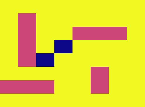
I liked how this code worked but I wanted it to display a red neopixel where there was a boat and a blue where there was not. I first designed the board setup that the computer would use, it looked like this:
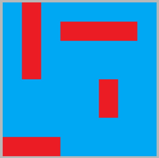
To display this I figured I would have to create a base color for all the pixels to be, blue, and then specify certain neopixels to be red. I asked ChatGPT how to do this and it gave me this code that when the correct coordinate is entered, it will light up red, if not, it will light up blue. I also wanted to be able to turn them all off by pressing 0,0. Here is the code that combines all of my needs for this aspect of my project. Final working code:
import machine
import neopixel
import utime

# NeoPixel strip configuration
NUM_PIXELS = 64
np = neopixel.NeoPixel(machine.Pin(27), NUM_PIXELS)

# Set up the keypad matrix
rows = [6, 7, 8, 9]
cols = [10, 11, 12]
keys = [
    ['1', '2', '3'],
    ['4', '5', '6'],
    ['7', '8', '9'],
    [',', '0', '#']
]

# Set up rows as outputs and cols as inputs
row_pins = [machine.Pin(row, machine.Pin.OUT) for row in rows]
col_pins = [machine.Pin(col, machine.Pin.IN, machine.Pin.PULL_UP) for col in cols]

# Set up timer for debounce delay
debounce_timer = machine.Timer()

def debounce_callback(timer):
    global debounce_flag

    # Resume keypad scanning after debounce delay
    debounce_flag = False

def read_keypad():
    for col_pin in col_pins:
        col_pin.init(machine.Pin.OUT)
        col_pin.value(0)
        for row_pin in row_pins:
            row_pin.init(machine.Pin.IN, machine.Pin.PULL_UP)
            if row_pin.value() == 0:
                col_pin.init(machine.Pin.IN, machine.Pin.PULL_UP)
                while row_pin.value() == 0:
                    pass
                return keys[row_pins.index(row_pin)][col_pins.index(col_pin)]
        col_pin.init(machine.Pin.IN, machine.Pin.PULL_UP)
    return None


debounce_flag = False  # Flag to indicate debounce delay
key = None  # Last key value
previous_key = None  # Previously displayed key

# Mapping between keypad coordinates and NeoPixel indices
pixel_map = {
    '1,1': 0, '1,2': 1, '1,3': 2, '1,4': 3, '1,5': 4, '1,6': 5, '1,7': 6, '1,8': 7,
    '2,8': 8, '2,7': 9, '2,6': 10, '2,5': 11, '2,4': 12, '2,3': 13, '2,2': 14, '2,1': 15,
    '3,1': 16, '3,2': 17, '3,3': 18, '3,4': 19, '3,5': 20, '3,6': 21, '3,7': 22, '3,8': 23,
    '4,8': 24, '4,7': 25, '4,6': 26, '4,5': 27, '4,4': 28, '4,3': 29, '4,2': 30, '4,1': 31,
    '5,1': 32, '5,2': 33, '5,3': 34, '5,4': 35, '5,5': 36, '5,6': 37, '5,7': 38, '5,8': 39,
    '6,8': 40, '6,7': 41, '6,6': 42, '6,5': 43, '6,4': 44, '6,3': 45, '6,2': 46, '6,1': 47,
    '7,1': 48, '7,2': 49, '7,3': 50, '7,4': 51, '7,5': 52, '7,6': 53, '7,7': 54, '7,8': 55,
    '8,8': 56, '8,7': 57, '8,6': 58, '8,5': 59, '8,4': 60, '8,3': 61, '8,2': 62, '8,1': 63,
}

entered_coordinates = ''
color_map = {
    "1,2": (65, 0, 0),   # LED at position 1,3 will be red
    "2,2": (65, 0, 0),
    "3,2": (65, 0, 0),
    "4,2": (65, 0, 0),
    "8,1": (65, 0, 0),
    "8,2": (65, 0, 0),
    "8,3": (65, 0, 0),
    "2,4": (65, 0, 0),
    "2,5": (65, 0, 0),
    "2,6": (65, 0, 0),
    "2,7": (65, 0, 0),
    "5,6": (65, 0, 0),
    "6,6": (65, 0, 0),
    # Add more mappings as needed
}

default_color = (0, 0, 65)  # Default color for LEDs not in the color map

try:
    while True:
        if not debounce_flag:
            key = read_keypad()
            if key is not None:
                if key == '#':
                    if previous_key != '#':
                        if entered_coordinates:
                            coordinates = entered_coordinates.split(',')
                            if len(coordinates) == 2:
                                row, col = coordinates
                                if row == "0" and col == "0":
                                    np.fill((0, 0, 0))  # Clear the NeoPixel array
                                    np.write()  # Update the NeoPixel strip
                                else:
                                    pixel_index = pixel_map.get(f"{row},{col}")
                                    if pixel_index is not None:
                                        print(f"Entered: {row},{col}, Pixel Index: {pixel_index}")
                                        color = color_map.get(f"{row},{col}", default_color)
                                        r, g, b = color
                                        np[pixel_index] = (r, g, b)
                                        np.write()
                                    else:
                                        print(f"Invalid coordinate: {row},{col}")
                            else:
                                print("Invalid coordinate format. Enter two numbers separated by a comma.")
                            entered_coordinates = ''
                        else:
                            print("No coordinates entered.")
                        print('\n')
                        previous_key = key
                else:
                    if key != previous_key:
                        entered_coordinates += key
                        print(key, end='')
                        previous_key = key
                debounce_flag = True
                debounce_timer.init(mode=machine.Timer.ONE_SHOT, period=50, callback=debounce_callback)
        utime.sleep_ms(10)

except Exception as e:
    print("An error occurred:", str(e))
Boxes
Draft Box
First I designed the box in Fusion 360 by creating a pattern with a checker box pattern. Then I exported it as a DXF
After that, I opened it in CorelDraw and created a 1.5-inch thick box.
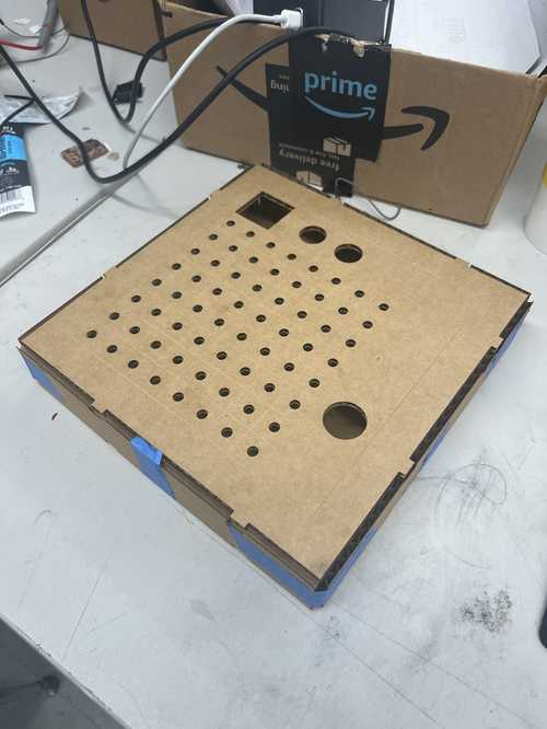
After that I sent it to the laser to be cut, I selected a cardboard cut engraved for my settings and sent it. Here it is cutting.
Then I assembled it and held it together with tape so I could see what it would look like fully together.
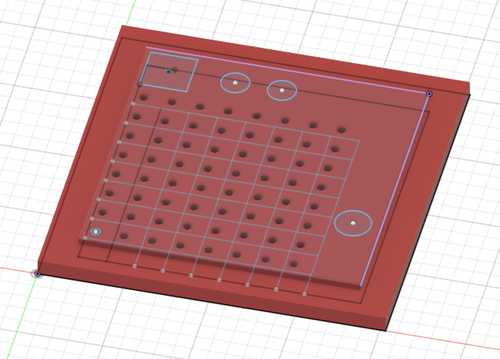
Final Box
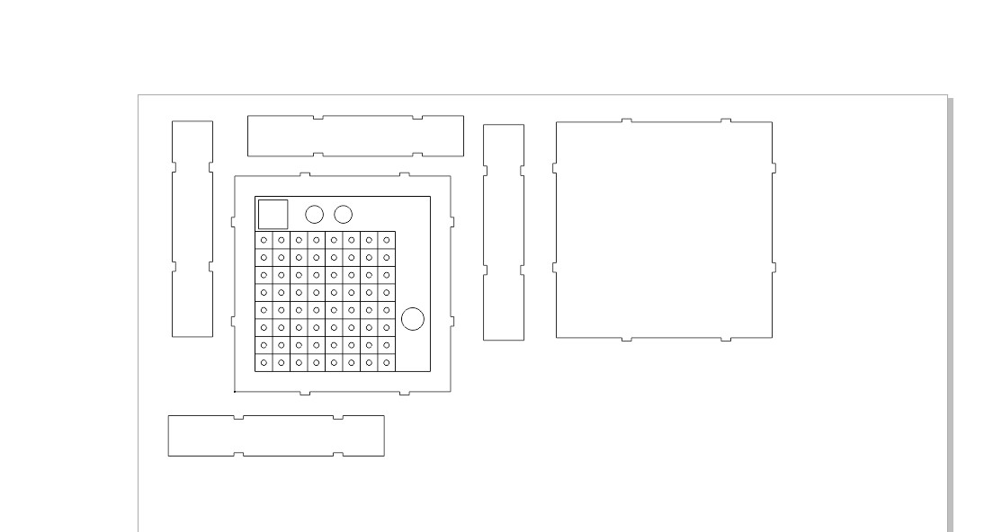
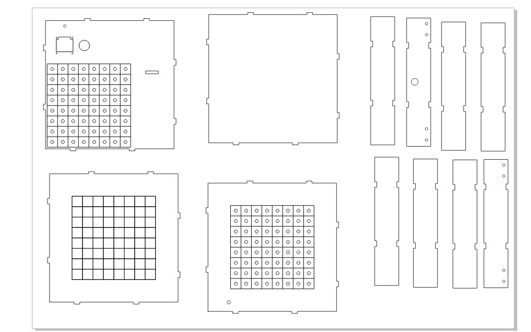
For designing my final box I made a few changes, first making only one button hole since I will only need one button with this new version, second moving the grid to the bottom left of the lower board to allow for the keypad to fit on the top, adding screw he’s on the back for the box for a hinge and for the OLED to be supported, and finally a hole in the front for the OLED wire and a hole in the back for the power cable. On the upper board, I added some holes for the light to go through and I added a small hole in the bottom left for the neopixel wires to feed to the electronics in the bottom. I also decided to make the box out of acrylic because it will give a cleaner look to the box. Here are the corel design files.
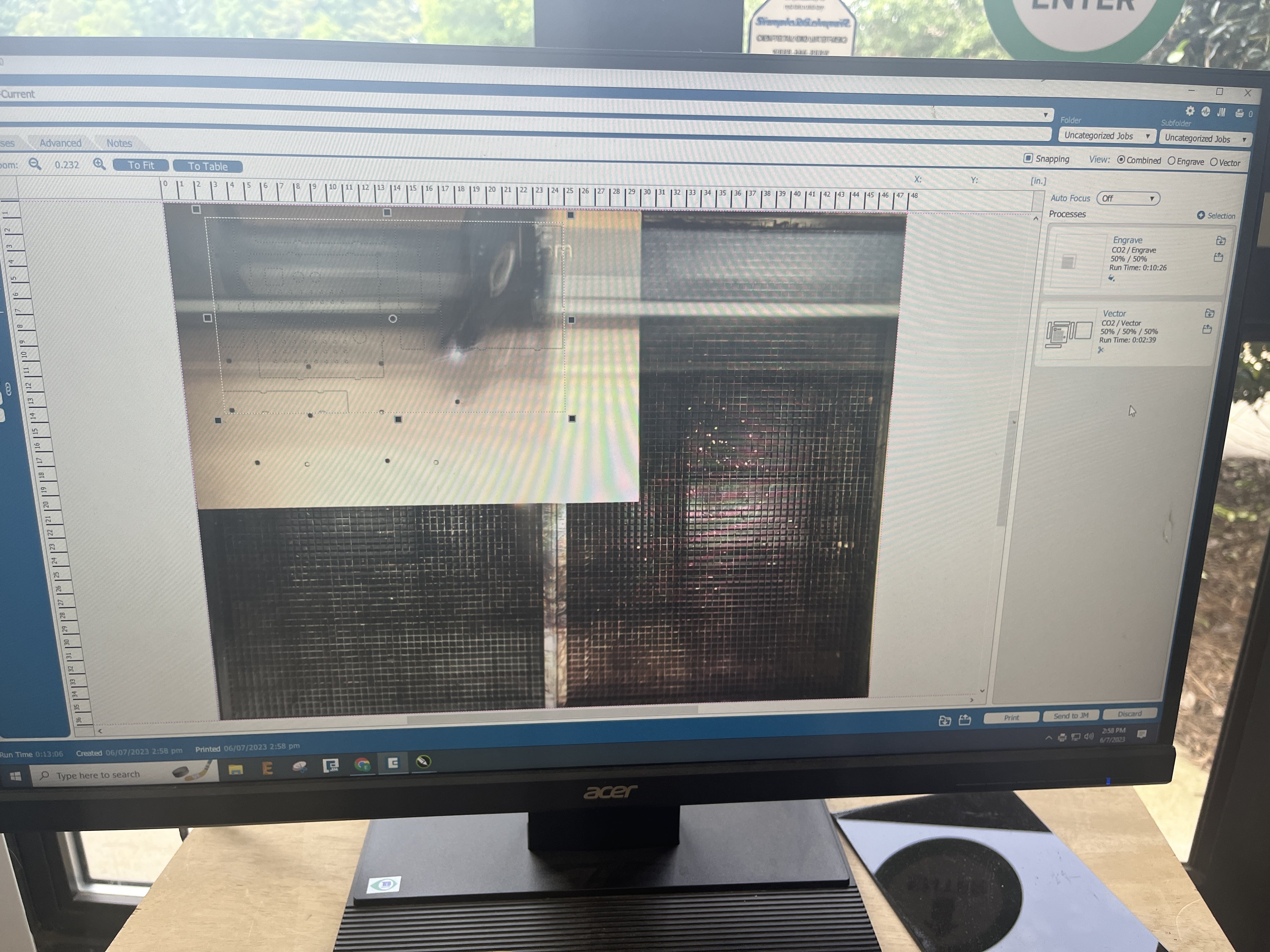
The next thing I did was send the cut to my laser cutter and separate my cuts into two separate cuts with the tops of each half box being copied and pasted to a new file and cut on a second cut on blue acyclic, the rest would be cut on black acrylic. I will use 1/8 in (3mm) thick acrylic for this and I chose my raster and vector settings as such, the raster at 300 dpi and the vector set for 1/8 in. I also turned on autofocus. Then I sent my file over to be cut. I pressed start on the machine and after about 20 minutes of cutting. I had my box. Then I assembled the box and used some tape to hold it shut.
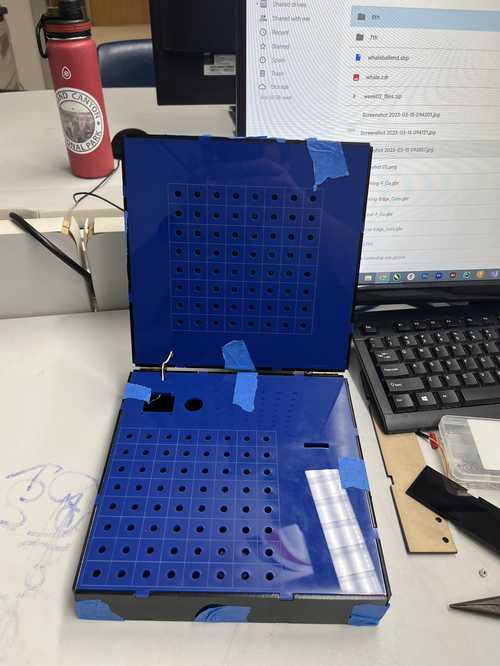
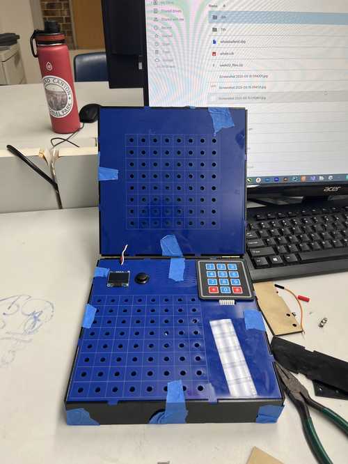
Then I inserted the components into the box to see what it would look like when it was done.
After that, I took the components out and used some quick-set epoxy resin to glue the boxes together. Then I put the components back in the box once the glue was dry. Here is what the final box looks like:
PCB design and creation
Designing and milling PCB for enemy’s guess (PCB 1)
Designing PCB 1
The first thing I did was open a new KiCad file and import two 4-pin headers and two 2-pin headers. The first four-pin header would be for the OLED and the second would be for the buttons. The first 2-pin header would be for the capability of UART communication and the other for power and ground input. Here is what the schematic looks like.
Then I opened the schematic in the PCB editor and did some routing. Here is what it looked like.
Here are the gerber and design files.
Milling PCB 1
I started by opening the Gerber files in Bantam tools software. After that, I selected a 1/64 and 1/32-inch flat-end mill followed by a .05 pcb engraving bit. Then I inserted a .005 pcb engraving bit and zeroed it. Then I probed for material thickness. After that, I started the mill and changed the bit when prompted. Here is a video of it milling
Then I took out the board and soldered my pieces on. Here is the soldered board.
Then I tested it.
Designing and Milling Final Board
Here are the final board files
Designing Final PCB
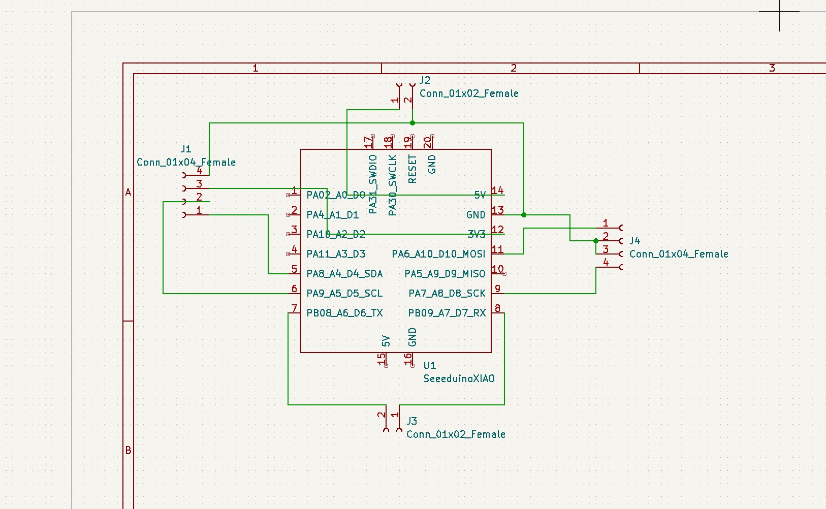
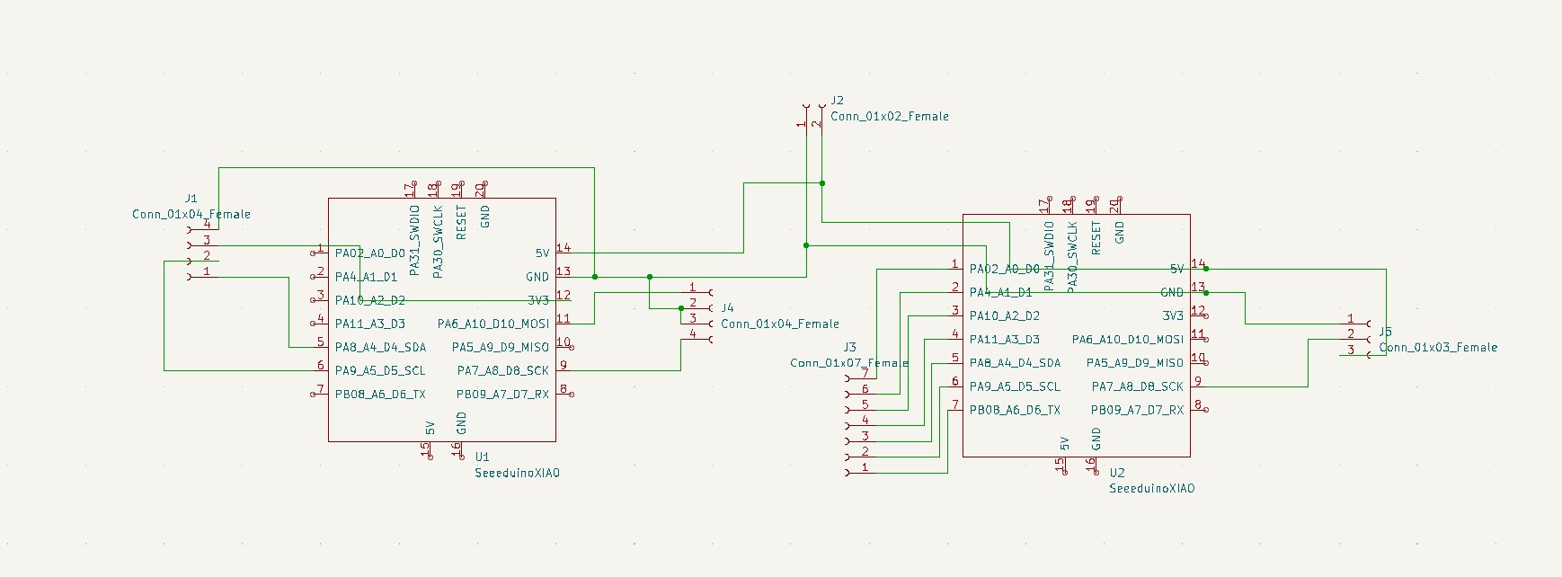
The first step I took in designing my board was adding some parts to the schematic. 2 seeed Xiao rp2040s, 2 four-headed pinouts, one for the OLED, and the other for the button with an extra pinout. I also added a 7-pinout for the keypad, a 2-pinout for power and ground, and a 3-pinout for the neopixel. Here is what the schematic looks like:
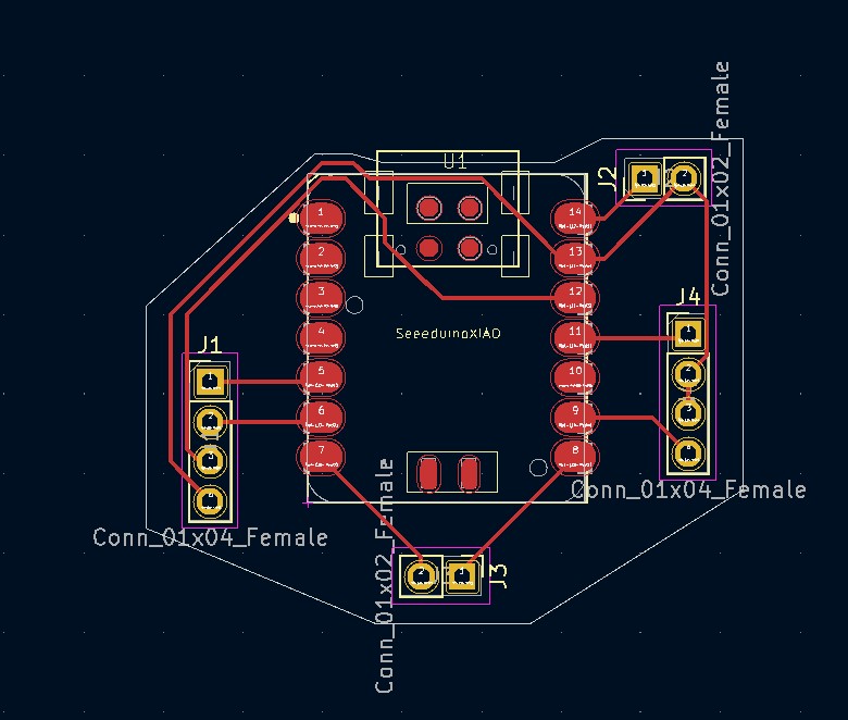
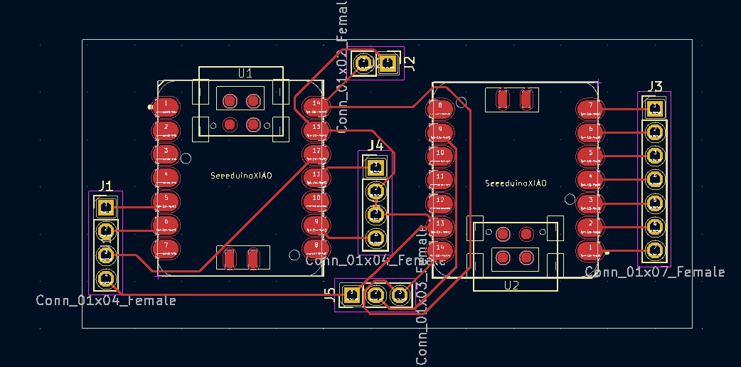
Then I opened the PCB editor and created the PCB. I first created some traces so they would work and not cross each other. Then I added a square around the design. Here is what the PCB looked like.
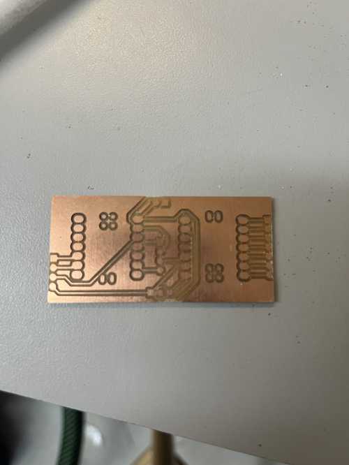
Milling Final PCB
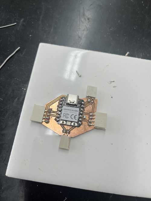
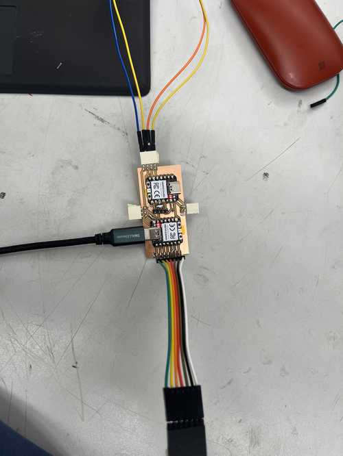
To mill this pcb I plotted the files on the F_Cu layer and the Edge Cuts layer. Then I sent them to be milled on another desktop cnc. I selected copper at the top layer and edge cuts as the outline. I selected a .005 pcb engraving bit, 1/64 in and 1/32 in flat-end mill bits. I then put a copper pad down and taped it down with Nitto tape. I then probed the z height and got 1.7mm. Then I milled it out, changing the bit when necessary. Then I took it out of the mill and soldered on the components.
3D Printing
Here are all the 3D printer files.
3D Printing Boats
The first boat I decided to print was for my idea with Freighter Feud. These ships would be similar to freighters and be square. I started by correctly spacing the lower pegs with the holes. I did this by creating a 5mm circle and copying that 16.5 mm apart 4 times. Then I added a rectangle around the circles that was 16.5mm by 33 mm and 8mm thick. Then I fileted the edges by 1.5 mm.
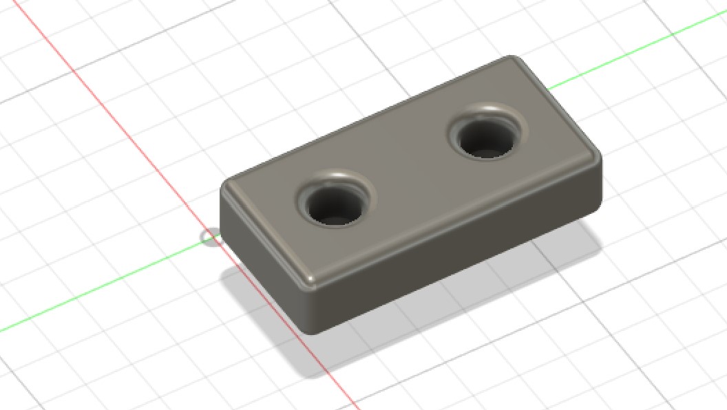
After that, I sliced it with a Prusa slicer and created the code at .2mm detail. I sent it to be printed and here they are.
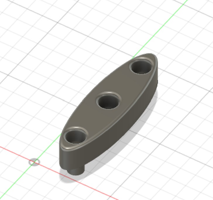
Then I changed the name of my game to Sink the Submarine. I did this because logically, there are no guns on a freighter. I decided to add the details and redesign my ships to look like submarines. The first thing I did was redesign my sketch and change the rectangle to an ellipse. I kept everything else the same. Here is what that looked like.
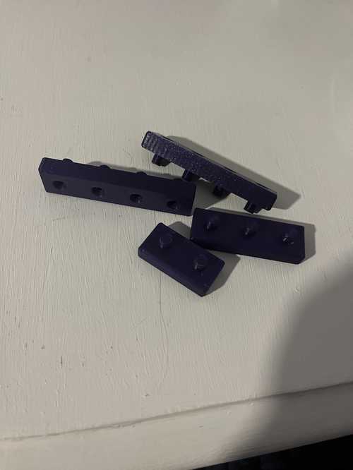
I followed the same steps as before, sliced it with a Prusa slicer, and sent it to be printed. Here they are.

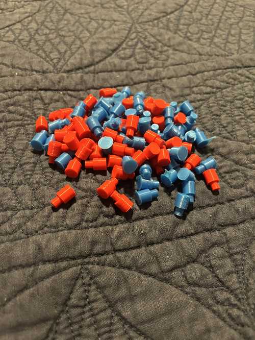
3D Printing Pegs
To make the pegs I created a 5mm circle and extruded it 15 mm. Then I added another circle that was 8mm in diameter around it. Then I extruded that circle 10mm. After that, I made a rectangular pattern that was 8 by 5 and spaced them so they wouldn’t touch. Here is what that design looked like.
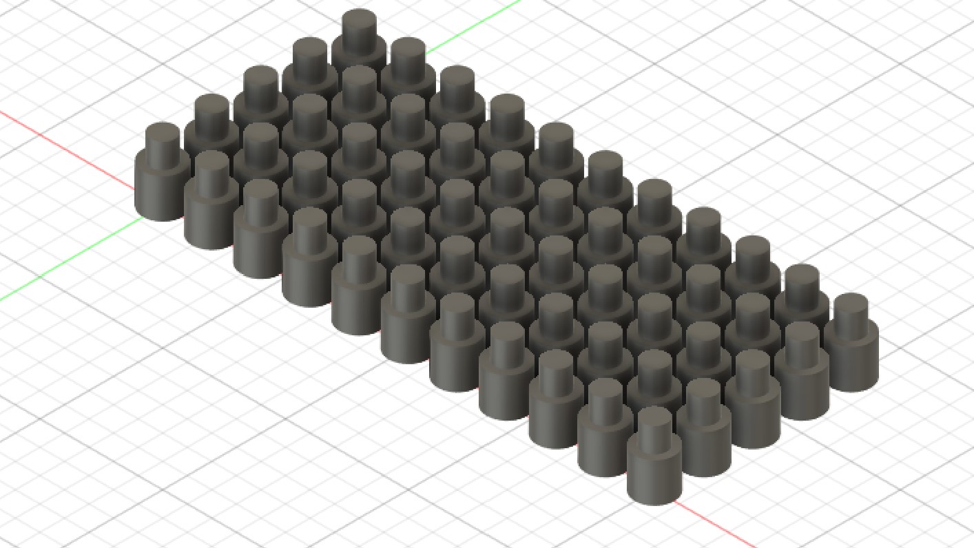
Then I did the same process as with the boats to slice and 3D print them. This time, I did two prints, one with red and one with blue filament.
Sticker Making
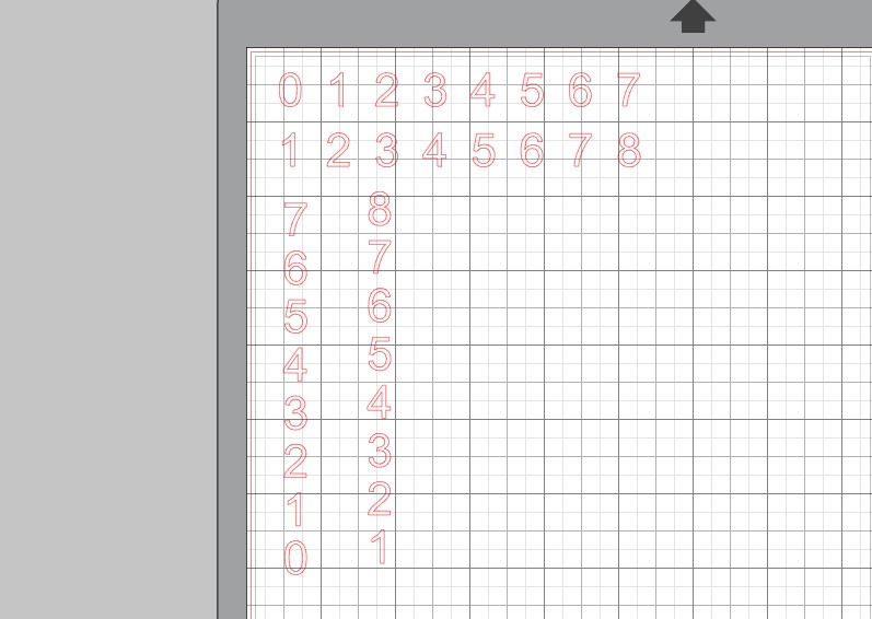
Sticker 1, the Numbers
I decided to make stickers as another aspect of my final project. I used the silhouette studio software and the cameo as my cutter The first sticker I made was of the numbers that would go around the grid as labels. I started by creating a row of numbers 1-8 and a second one with numbers 0-7. I had to do this because one of the two codes I was using did not recognize 0,0 as a location and caused many issues. I then created another horizontal version of this with the same number layout. Here is what that design looks like.
After that, I sent the design to the laser to be cut. I chose black satin vinyl because it will match my theme of black and blue. I first stuck it to the sticky pad and then pressed the load material on the cutter. After that, I selected vinyl as my material and sent the file over to be cut. After it was cut, I removed the extra material with tweezers, leaving me with only the numbers. Then I put some transfer tape on top and transferred the numbers to the board and they aligned perfectly.
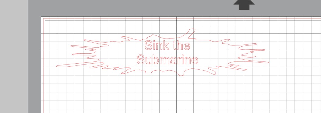
Sticker 2, the Title
The second sticker I made was a title for the top of the game. First I found this PNG of water splashing and imported it into Silhouette Studio.

Then I used the trace tool to take an outline of the splash and I stretched it out until it was more of a rectangle than a square. After that, I added some text in the center with “Sink the Submarine” in the center.
After designing it I did the same process as before, here is the final sticker and the completed project: