4. Computer controlled cutting
This week I learned to cut on both the vinyl cutter and the laser cutter. Understanding both the work flow for each and how to use the machinery were the challenges. I also needed to design a construction kit to be cut on the laser cutter. The requirement was that the design involve parameters.
Goals for the week
- Described the group assignment
- Explained how you parametrically designed your files
- Documented how you made your press-fit kit
- Documented how you made your vinyl cutting
- Included your original design files
- Included your hero shots
Useful links
Vinyl Cutting
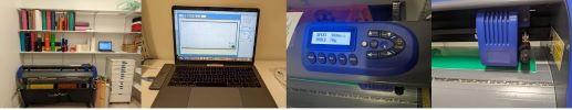
The process used to vinyl cut is very straightforward. Brandon showed us how to use Wheaton’s vinyl cutting machine, the Titan 2. To demo the machine he found a png online and downloaded it to the mac attached to the cutter. The software used on the mac is Sure Cuts A Lot. You simply need to import your png into the program and then place and size it. The easiest position on the screen is the lower right corner. Once you have your image in the corner and the size is what you want (just change height or width and they will both change accordinging) you have to make sure the machine has the appropriate settings for your cut and that the vinyl is lined up with the cutting utensil. The Fab Lab set up is as below. Left to Right: the Titan 2 with the various vinyls for both fabric and non-fabric purposes. The mac attached to the cutter, with Sure Cuts a Lot open; the interface to change the settings for the cutting and to move the cutter to an origin; an image of the cutter ready to go at the right corner of the vinyl.
I took my design from last week’s Inkscape intro to vinyl cut. This design is not the easiest for cutting because there are lots of little bits that need to come out, but I wanted to cut something that I had designed after practicing cutting with images I had found online.
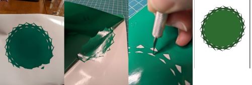
Below is the series of images. Left to Right: A failed vinyl cut (I think I failed to determine the right settings so it didn’t cut through all of the sides); peeling off the backing; picking out the little pieces; the original Inkscape design.
Note that I did not pay enough attention to the cutter settings when I was practicing and I think that was the issue with the failed cut. The two aspects that you can control with the Titan 2 are the speed and the force of the cut. For speed, a good starting point is 300 mm/s and for non-apparel vinyl, the machine works best at 78g. When you turn the machine on the default speed is much higher than 300 mm/s. This could definitely cause the finer details to be missed when I cut my logo. I will also say that I may have misjudged the placement of the vinyl. There are gears that lock the vinyl into place. I was ttrying to use up pieces of leftover vinyl when I cut. This is usually much less wide than the rolls of vinyl. Therefore it doesn’t catch as many of the gears to hold the vinyl in place for cutting. Going forward I need to pay more attention to speed and setting the origin.
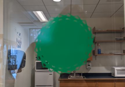
Final image of Demeter’s crown on the window for my office:
Laser Cutting
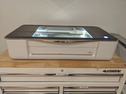
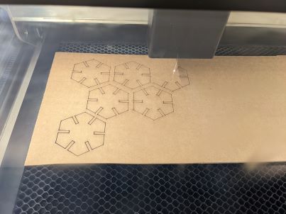
Wheaton has 2 laser cutters. The Fab Lab recently moved into a new space, so only one of them is up and running. That one is the Glowforge Pro. This is a great small machine that feels safe and is very straightforward to use.
To use the machine you need to design something 2D and then import it into the Glowforge (online) app. From that it is an easy process to select material and get things cut.
I used Fusion 360 this week, but Inkscape would also be useful in the future. Needing to incorporate parameters into the work required something like Fusion 360. At a certain point I thought I might just switch to OpenSCAD because I am still working on finding best practices with Fusion 360. But I persisted, watched some videos that helped with that extrude command and finally was able to make something that worked. More on that below.
Group work
To begin learning about the laser cutter Brandon and Spencer showed us the workflow from AI to Glowforge. Together we cut some test pieces so we could see the differences between engraving and cutting. Brandon also changed the settings on the laser so we could see how changing power and speed impacted the cuts. Below are the 4 different test cuts using cardboard. The Glowforge app has a built in setting for 1/8 inch cardboard, so we started with that. Then you can see that the engrave and cut settings were changed, as noted on each of the test squares.
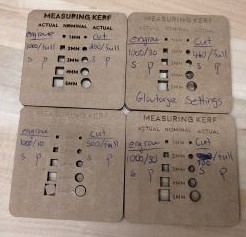
You can see the differences in speed and power and how they impact the cuts in the image above. The top left was the slowest cutting speed, with the laser at full power for cut. This resulted in almost burnt looking cuts. While the image directly below that was much faster and at full power. The speed was too fast to effectively cut all the way through the cardboard, as you can see the bottom holes still have the inside pieces in there. This one also had the least powerful engraving, which you can see in the difference of the words at the top of the square: they are barely there! These differences are important to keep in mind as we move forward with designs implementing laser cutting. We want to make sure we set the laser to get the desired outcomes. This is of course only one part of the equation. We also must make sure our design is good. See more on that below.
We used a caliper to calculate kerf for cardboard with these different settings and for the standard wood that is used in the lab. It is important to remember to do this if material is changed to understand the width of the laser beam and how that impacts the size of the end result based on what you design.
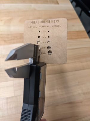
KERF?? What is kerf? As I said above, the laser beam has a certain width. So if for instance you want a square that is 5 inches on each side and you create this in a software with those exact dimensions, when you take your square out of the laser cutter you will find that your sides are less than 5 inches. The question is “by how much?” This is what the kerf is - the width of the laser that you must factor into your designs so your pieces come out with the precise dimensions needed.
From our experiments above I calculated the following. Note that in all cases the power was set to full, so we will look only at laser speed below.
Glowforge settings for 1/8 inch cardboard:
Cut speed 460: average kerf of .45mm
Other cardboard settings we input:
Cut speed 200: average kerf of .51mm
Cut speed 300: average kerf of .43mm
Cut speed 500: average kerf of .45mm
For the piece of wood cut with Glowforge settings I calculated an average kerf of .25mm. Note that it makes sense that the wood, a harder object, would have less kerf.
Individual work and design of construction kit
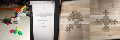
I knew that this was going to take several tries to get right. I first just designed a puzzle piece inspired by my kids’ 3d construction kit where all the pieces were VERY small and fit together in many different ways. Below you can see the puzzle pieces and the assembled unicorn. The design of the pieces is pretty simple, so I did that in Fusion 360. Each segment of the piece was to have the same width of the thickness of the cardboard so they would fit together. The cardboard is 1/8 inch thickness, so these would have been very tiny. I set the parameters and did not check on the conversion from inches to mm and therefore one mistake was that I had the measurement too large. I knew these would not be perfect, but this experiment was really about trying out the process from start to finish to understand how to make a better final product. One really big lesson I learned was that my design approach was really awful!! In Fusion 360 I made a rectangle and then made 6 individual smaller rectangles to cut out of the larger rectangle. Well, when I went to cut using the Glowforge I got the message you see below. It says that my design very well may lead to my pieces catching on fire. I had no idea why. Turns out that I had MANY overlapping lines. So when I was watching the cut and the laser went over some of the same spots up to 4-5 times, clearly that is where the fire hazard was. Lesson learned!! In the end nothing caught on fire and below you see that the pieces were nice and I could put them together. They only fit together on the 2d surface however because of the design flaw. This was all a great learning experience.
Next I decided to design pieces that all had a notch in them so that the pieces could just slide together. I think I was inspired by Whitney O’Reardon’s amazing tree design from last year’s Fab Academy. My first piece that I designed was a rectangle with one side having 2 notches and the adjacent side having one.
The very first step was to define some parameters. They were fairly straightforward. Here’s the image. The tablength is described below.
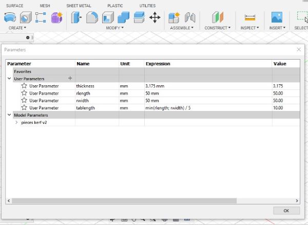
I began the design by creating a simple rectangle with the edge lengths defined by the parameters rlength and rwidth. Note that I had these set to be equal for the final output but defined them independently so rectangular pieces (not squares) could also be made. Then I extruded the entire rectangle. Next step was to remove area to make notches.
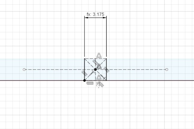
I created a new sketch on one side of the extruded rectgangle. To place the one central notch on this side I created construction lines and centered the rectangle on them. The vertical line was easy to place because Fusion 360 indicates where the center of the line is when you are hovering around trying to place the line. Then the second line could be anywhere in the rectangle and then moved into place using the “midpoint” constraint with the 2 lines highlighted. One important thing to note here is that you have to make these lines construction lines. You do this by clicking “x” either before you make them, or you can select them and hit “x”. Then you have to remember to hit “x” again to stop construction mode. This took a few times for me to actually do it correctly! I set the width of the notch using the “thickness” parameter. This thickness is the thickness of the material, thus it’s 1/8in or 3.175mm.
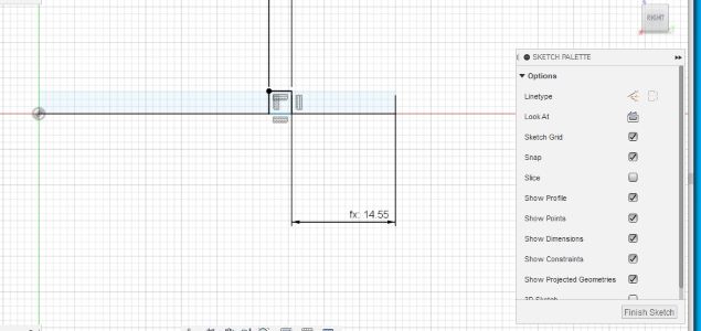
On the side with 2 notches I used several of the parameters and constraints. In the image below you can see the distance from the edge to each notch depends on parameters. It is set to (rlength-2*thickness)/3 so that the space that is not taken by the notches will be 1/3 of what is leftover after subtracting the 2 notches. I repeated this construction on the other end of the same face to get 2 notches equally spaced along the side.
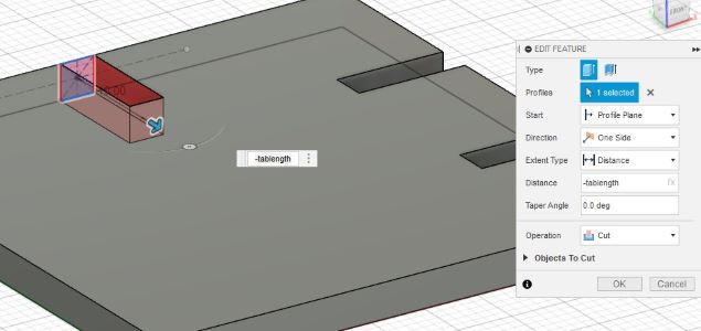
In both cases I used “extrude” on the rectangles that I made to make the notches. It is clear that the width of the tab has to be the same as the cardboard thickness. However, the depth of the tab (the amount to extrude) was to be determined. I used a parameter called “tablength” depending on the smallest of the 2 sides of the rectangle. I wanted to ensure that the tabs didn’t interfere with each other, so I used the minimum side length and then divided by 5. Based on watching the box construction video I found that there was a whole page of mathematical commands on the Fusion 360 reference page. Being a mathematician, this made sense and made me excited to look for a min command.
The things to pay attention to with extrude are the direction and the distance. Really these are related. In the screenshot below you see that I used -tablength. This is all dependent on the direction of the arrow. Without the negative the extrude would have gone OUTSIDE the piece. I thought about making some pieces with outside tabs to make the set have more types of intersection possible, but I kept things straightforward this week.
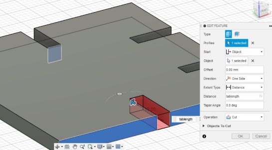
Now that I had created 2 sides of my piece I had originally thought I would have to do the same steps all over again. There has to be some way to copy and paste! Well, it turns out that “extrude” is super useful in many ways and watching the box construction video showed me how to copy one side to the opposite side by extruding. In the image below you can see that I used extrude and changed the settings. The important things to note: start at an object. You see that the side of the rectangle is highlighted across from the notch which is highlighted. This creates a notch FROM the highlighted face that is exactly the same cross section as the highlighted one. You can see I set the distance to be tablength again here.
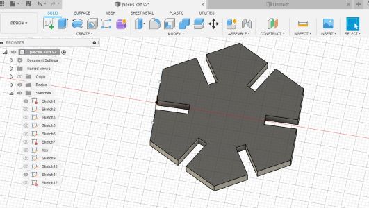
I decided once I had rectangles that I would also make hexagons with center notches on each side. I made them in the same file since then I could use the same parameters. I decided that the hexagon should use one of the sides of the rectangle for its radius. Fusion 360 has a create polygon option where you can specify the number of sides and determine if you want the shape inscribed or circumscribed inside a circle of a certain radius. I chose a hexagon with radius of “rlength”. Then I used the same process as above to take notches out of the center of the sides using extrude. Below is the final 3d version of this object. Note: these are regular polygons, which was exactly what I had wanted here. There are probably ways to alter these if you want irregular polygons.
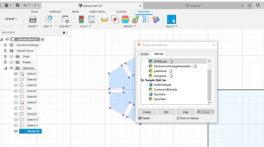
Before I was done with my shapes, I needed to take into account kerf. I thought I was going to have to add a parameter and make sure I added that to all my cuts, but then Spencer showed us an add-on in Fusion 360. If you go up to Utilities at the top of the Fusion 360 screen and click on Add-ins you can add DXF4Laser, as you see in the screenshot below. Then you want to make sure you run this before you finish your project. I used the kerf measurements from above to account for kerf (.45mm) for our laser cutter.
Finally I was ready to export my Fusion 360 file as a .dxf and bring them into Adobe Illustrator. Here I had some trouble getting the right lines out of Fusion 360 and into Adobe Illustrator. For a long time I was getting extra lines (see almost setting fire above). I think it was that I didn’t have the right process to get just the top surface. Some important steps follow.
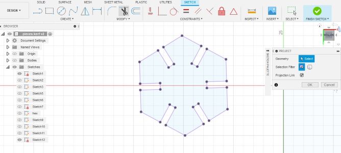
To get just the top surface you should create a new sketch and then choose “Project/Include” from the Create menu. Select only the top face of the object. If you can’t select the whole face you can select each edge individually. Then THIS is the sketch you want to export by right clicking on the sketch in the left menu and selecting “Save as DXF”. I had everything else hidden when I did this step. I don’t know if that is actually necessary, but this was the process that eventually worked! Here’s the final step of “project” for the hexagon piece. You can see that the surface you want is selcted by the presence of the purple lines and vertices. If you don’t see all that purple you may not have finished your sketch.
I exported both the hexagon and rectangle faces into Adobe Illustrator to save them as svg files to import into the Glowforge app.
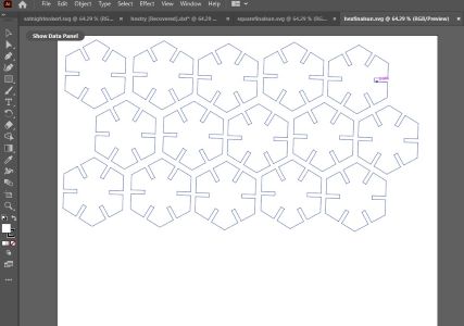
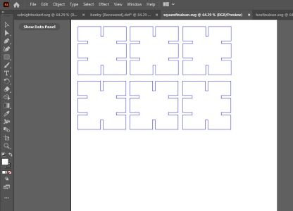
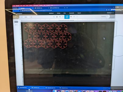
In the Glowforge app I copied and pasted as many of the shapes into the space that I had according to the carboard that I had to use.
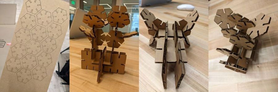
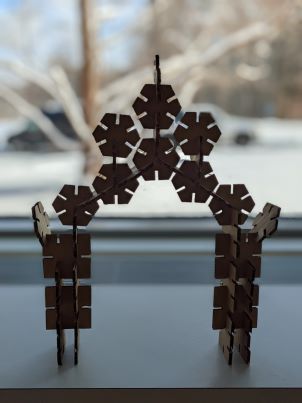
In the end I made about a dozen of each shape and put them together in a variety of ways. I decided I had created a collection of objects that can be used to make various sculptures. One of my classmates suggested an arch and that’s the one I thought was the coolest, at the bottom.
Design Files
Adobe Illustrator hexagons and Adobe Illustrator rectangles