5. Electronics production
UPDATES: June 21, 2022: Jason uploaded new instructions because there were flaws in his previous board. This new one is one that comes from the Fabcloud. You can find all the new instructions from Jason here with additional necessary info from the Fabcloud gitlab.
The process will remain the same, so I am only going to update where necessary in this page. In order for the page to keep the same format as my other assignment pages I will do that at the very bottom of the page. You can find the details, hero shots, files, etc there.
OLD WORK: This week we learned how to mill and solder PCB boards. We also were to program the board. This week was a mixed one in terms of success. I would say that I learned some skills but not enough of the context for how these things work. That was fine up to a point. In the end my board didn’t work. Jason Goodman tried to help me but in the end it still didn’t work and I still don’t know enough to trouble-shoot this to get it to be functional. I Look forward to learning more about HOW these things actually work so I can maybe go back and fix this.
Goals for the Week
- Linked to the group assignment page
- Documented how you made (mill, stuff, solder) the board
- Documented that your board is functional
- Explained any problems and how you fixed them
- Included a ‘hero shot’ of your board
Group work
At our lab we split into 2 groups to learn how to use the 2 mills at Wheaton. My group learned how to use the Sainsmart Genmitsu 3018 PROVer while the other group learned the Roland Monofab SRM-20.
To learn about the mill we used the test file to determine the level of detail we could cut. We used a 1/64 blade to cut the inside since that is what we will use to cut traces and a 1/32 for the outside since that is what we will use to cut the outside. The images of the line test, both the input and the milled board are below:
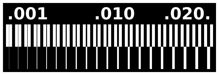
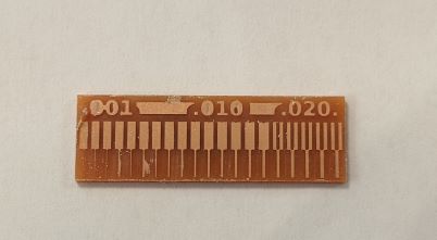
You’ll see that the results were mixed. As might be expected we didn’t get the cuts down the left side of the board. This is because the blade we used was too large for that level of precision. When we told the software (MODS, as explained below) the specification of the equipment it didn’t even attempt to cut those lines at the end because it knew it was not possible.
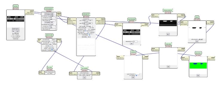
The mods output for this test is below.
Creating my own board
I followed the instructions written by Professor Jason Goodman, of the physics department at Wheaton. He shared step-by-step instructions with us in this google doc.
Milling the board
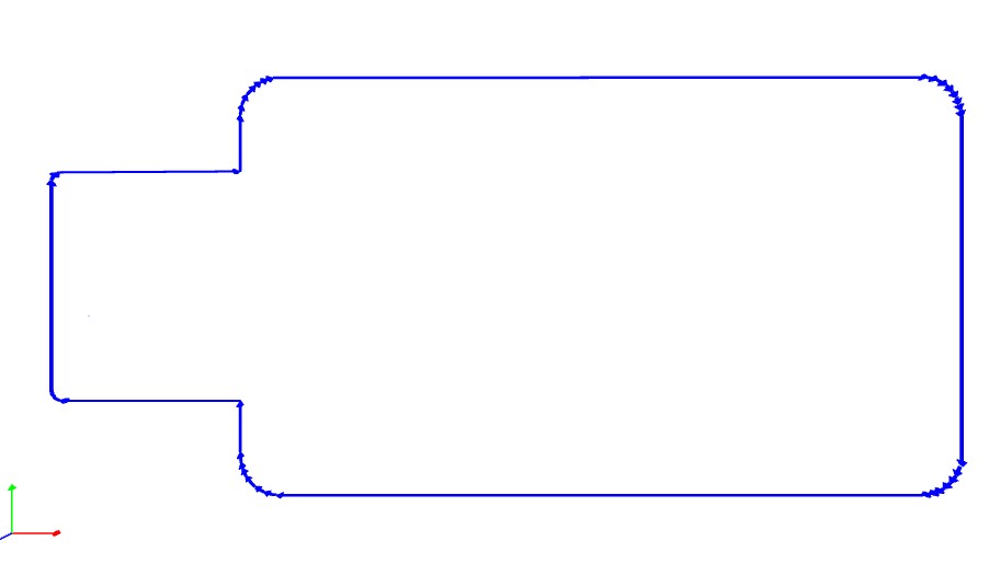
Jason designed new boards for this year’s lab. The one that is in the Google doc linked above does not have LEDs. I went with the “blinky version” that had 2 LED lights on it. You can find all the details for this board at Jason’s Github for this board. The outline of the board and the traces were designed as below

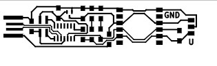
Note that both of these images are reverse in their black and white. The mill cuts the black and leaves the white. So it was important to remember to invert the image in MODS.
MODS
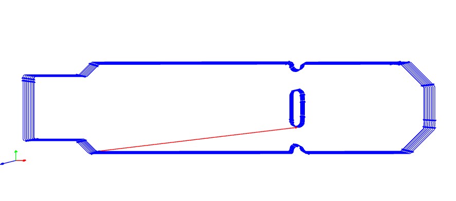
In order to turn these files into something that computer could send to the mill we used the MODS program. In this program I was able to input the specifications for the mill so the output file would be usable. I used the specifications that Jason laid out for us in his other Google doc. The output from MODS is pretty cool. You can see all the individual cuts that will happen when you use the mill. For instance, here’s what was produced for the outline of the board.
Sainsmart
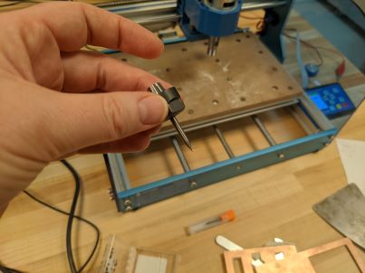
To begin using the mill we need to choose the size of the blade and make sure it’s secure.
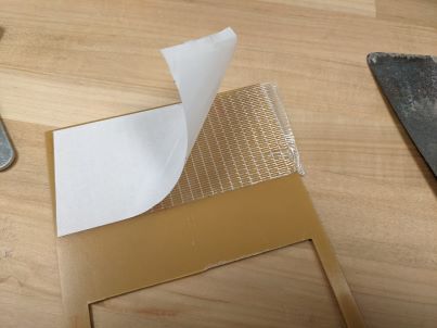
We placed the board material on the bed of the mill with double stick tape.
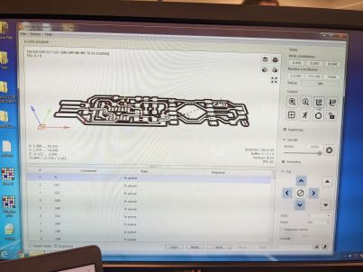
Then I opened the files from MODS in the program Candle on the computer attached to the Sainsmart mill. Here’s an image of the screen with Candle running. You can see the origin to the left on the screen.
Candle allows you to define an origin and find the zero height for the z-axis. We did this using a z-probe, as pictured below. This allowed us to use the software to determine where z was zero. I found this was not a totally fail proof approach when I was cutting on my own.
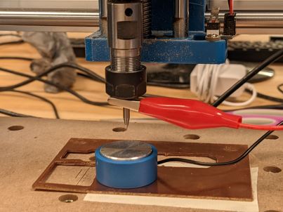
In the end I came out of the process with a better understanding of how to deal with the z-axis and a board that was cut pretty well.
Soldering and Stuffing
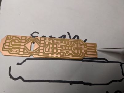
Before I could start soldering I scraped the end of the board to get rid of the extra copper there.
I have never soldered before. Our instructors showed us how to solder with both the soldering iron and with paste and a heat gun. I mostly used the paste and heat gun, but in the end I think it might have been better to go with the iron because the paste ends up spreading with the heat, which mostly seemed ok, but I think it ended up in some unexpected places (see below) and I couldn’t get rid of it sufficiently.
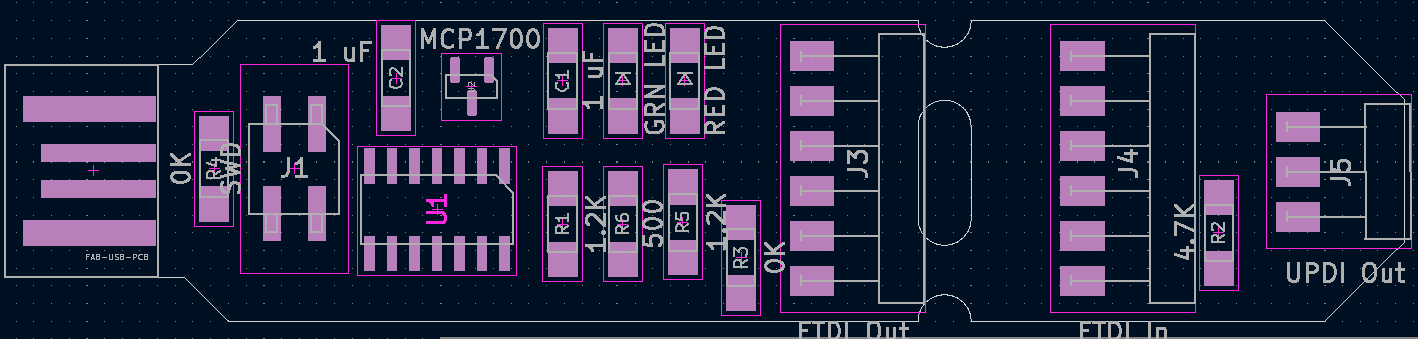
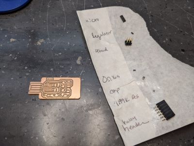
There were LOT Of tiny parts for the blinky board. I followed the schematic given by Jason:
What I found very difficult is that I have NO IDEA what any of these pieces do. Jason had set aside a collection of the pieces for us, but some were missing. Some of the students working in the Fab Lab were helping us find them but I had no idea what to tell them I was looking for. It’s been over 20 years since I took a physics class, so capacitor, resistor, etc?!!?
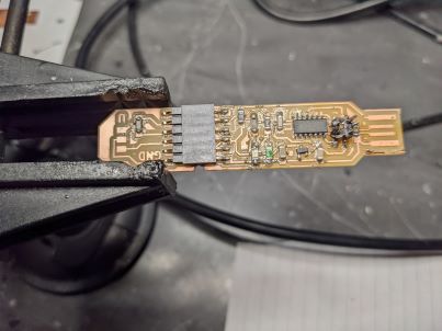
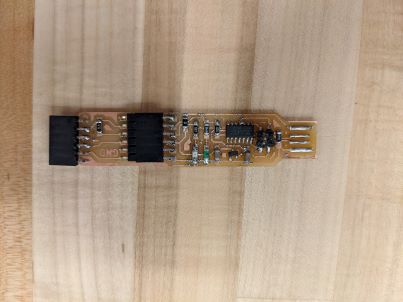
Anyway, we found all the pieces and over 2 sessions I soldered everything into place, as seen in the finished board below. Here’s an image of my work partway through.
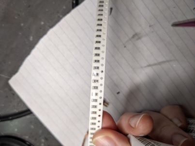
And a look at the tiny tiny parts…
To use the soldering heat gun and paste, you set the heat to somewhere between 400 and 700, put the paste where you want to attach the component, lay the component on top and then apply the heat. Often as the paste heated up it spread out so it was necessary to keep tweezers in one hand and the heat gun in the other to be able to move the piece back in place. The key with the paste was heating it until it went from grey and murky to shiny and silver. The amount of soldering paste was small so this wasn’t always obvious to me. Did I mention things are TINY!!!!!
The blinky design requires you to pay attention to orientation of the LEDS and the computer part. I put all of them on upside down the first time. So removing parts isn’t so bad. The best method we were taught is to hold the board with tweezers by the part you want to remove and then use the heat gun directed at that part. What happens is that the solder heats up sufficiently so that the part unattaches from the board and gravity leaves you with the component in your tweezers as the board falls to the table. So maybe don’t hold the board too high so that it only falls a small distance. Note: there aren’t many photos of active soldering because it’s pretty impossible to take photos while you are doing this since you are using 2 hands and using 400-700 degree heat!!
Trouble-shooting board construction
The z-probe caused me a bit of trouble. When I tried to use it it shut down the machine a couple of times. It turns out that the wires were placed in a position that kept tripping the kill switch. This was frustrating because the first time I went to mill the z-origin was too high and I needed to reset it. I wanted to be able to cut right over the initial cut as not to waste material, but then when the machine shut itself down, the coordinates reset and it was impossible to put it back to the same origin. After this happened once I started recording the origin where everything stopped so I could reset it appropriately. This really seems like lots of extra work for no good reason. However we didn’t figure this out (I had help from Tuna who was working at the time) until the very end. Next time I use this mill I will be VERY careful with the z-axis. I think if you don’t go up too high and you’re careful with the wires for the z-probe you should be ok. I hope.
I had to start the trace cut twice. The second time it worked. Then when I went to cut the outside we lost the coordinates and Tuna helped me approximate the origin. We got pretty lucky and it worked out, but I really thought I was going to be starting over for a third time.
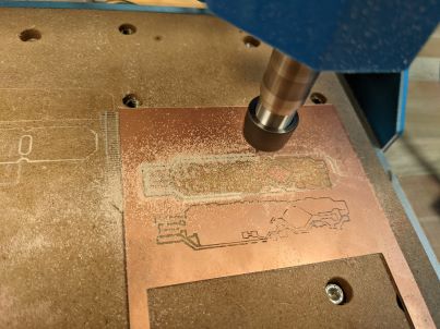
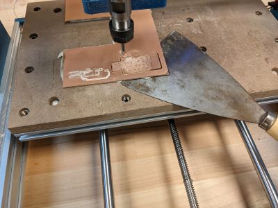
Here’s the successful board being milled.
Making the Board work
Once the board was physically created we needed to program it. Again, there are really good instructions for this in Jason’s Google doc.
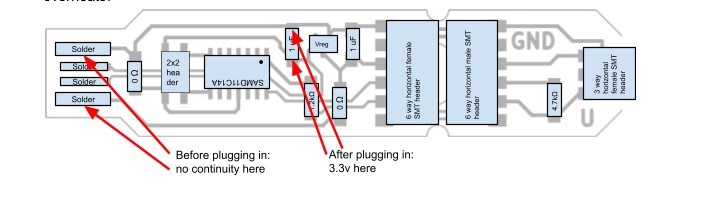
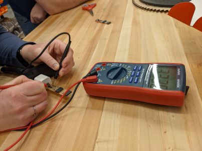
First stop is the Smoke Test. Following Jason’s directions, I used a multimeter (only vaguely understand how this works, but everyone kept saying how useful it was. Looking forward to learning more so that it helps in construction next time.) to ensure there was no continuity between the outer contacts of the USB. Then I also was able to see that the right amount of something was flowing through the 2 capacitors. Jason created the following helpful diagram for the other version of the board. Since I had 2 capacitors, one had 3.3V and the other 5V. Sarah captured a photo of me doing the smoke test - note the 3.3v reading on the multimeter! Yay! I thought I was almost done!!!
After the smoke test, the first step to Program the board was to download the Arduino IDE. Using the ATMEL Ice in-circuit programmer I burned an Arduino bootloader onto the microcontroller. Jason says that this “teaches the chip how to speak USB so it can communicate with the Arduino IDE for further programming.”
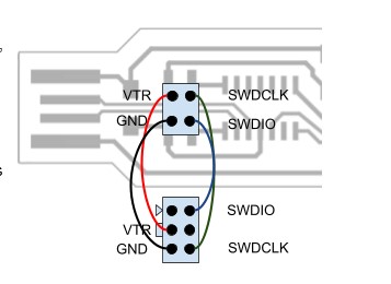
During this step you have to atttach the ATEML Ice in-circuit pogrammer to your board using Dupont jumper wires according to the diagram below. I checked to make sure I had the right configuration a few times.
Failure
After going through the bootloading step you should be able to unplug all the wires and plug the board directly into the computer and have it recgonize the board. This is where everything failed for me. I plugged it into my computer and my computer gave me a message that it did not recognize the USB device.
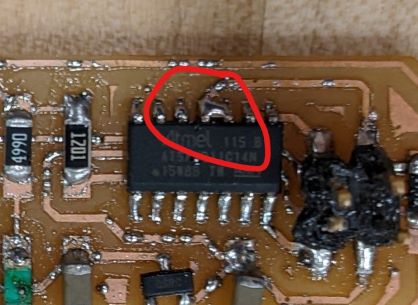
Jason was helping me try to figure out what was happening and looking at the board there was an extra blob of solder that may have been connecting the pins on the computer piece. The 2 pins connected caused the whole thing to not work.
So I removed that piece (to solder it for the third time, because of course I had already put it on upside down once). I struggled with getting the solder off so that it wasn’t connecting more things that weren’t supposed to be. I worked on it for awhile, a classmate tried to help me. We used braid to try to remove the solder, we used the solder sucker and then in the end tried to put it back together. It still didn’t work.
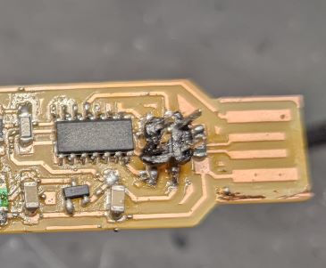
There was another possible problem that may have been the issue. I don’t know whether it was the computer part or the 4 pronged part we used with the programmer. When using the multimeter one of the 4 prongs had reacted as though it was attached where it wasn’t supposed add to be. So perhaps I should try to reattach that. Here’s the first problem: when attaching that I melted it really badly.
I thought I might try to get a new one to put on there but there weren’t a ton of pieces left and I wanted to make sure there were enough for my classmates to use. So I need to go back and try that once everyone else is done if there are any spare parts. I had a WICKED time getting that on because it doesn’t sit flat and I was trying to make sure that the leads lined up with the board. Hence the melting....good news is that I did help a classmate get theirs on later. I hope their board ended up working!!
So I know I need to go back and try to finish programming my board and then test to see that it worked.
In the end this was a rollercoaster of a week. I definitely learned some new skills but in the end have no working board.
old Files
Outline of the blinky board jpg
Traces of the blinky board jpg
The outline of the blinky board svg
The traes for the blinky board svg
New construction June 2022
Parts List
- U1: Regulator_Linear_LM3480-3.3V-100mA
- U2: ATSAMD11C14A-SSNT SAMD microcontroller
- J1: M20-8750242 2.54mm SMD 2x2 2 header
- J2: M20-7910642R 2.54mm 6 way horizontal female SMT header
- R1: 1206 SMD resistor 4.99k
- R2: 1206 SMD zero-ohm SMD jumper
- C1: 1206 SMD 1uF ceramic capacitor
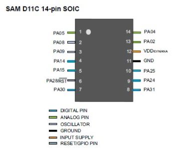
Note: this is the only time we are not using an ATTiny1616. We are using the microcontroller listed above. Some quick stats: SAMD1/2x series, ARM Microcontroller, 16kB memory, 32 bit Data bus, 48 MHz clock, 12 I/O pins (much smaller than the Attiny), 4kB RAM, voltage between 1.62 V and 3.63 V (so also smaller than the Attiny). Data sheet is available at the mouser site above. Here’s the pinout:
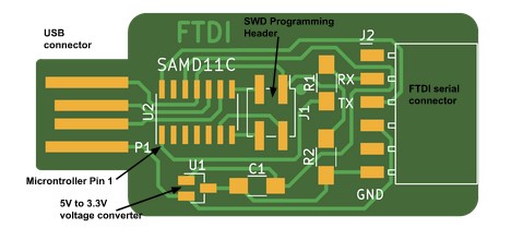
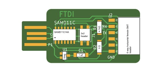
Here’s the image of the board layout and the “soldering map”:
I download the png files, run them through MODS, as in the steps above and then use the Sainsmart to mill the board. The one thing to make sure to note is to change the dpi (it says this in the instructions, but of course I didn’t do it). I forgot to and the default was 72 so it was going to take 4 hours and be huge. Whoops. Went back to mods and fixed it. The traces now take 13+ minutes.
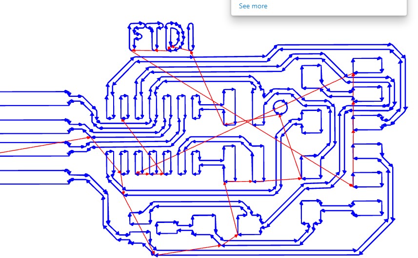
Here are the trace outputs from mods
Of course I still struggle to get the z-height right. The first go is too deep, so I stopped it and restarted with a higher z-origin.
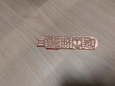
Images of the attempt and the final:
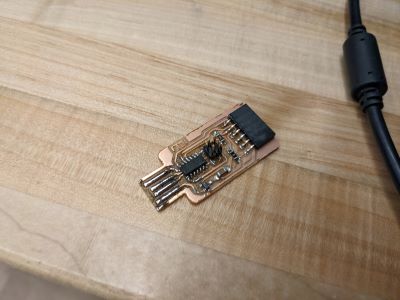
Then I soldered the board using all the parts as described above. Image of my final board, soldering prep and soldered board:
I followed the directions in Jason’s doc to program the board. First I did the smoke test. I checked that VCC and GND were not connected by using a multimeter to check for connections - no Beeps, so I’m good. Then I plugged the board into my computer and checked to see that there were 3.3 volts across the capacitor (set multimeter to the 200 V setting) and that also worked.
Then I tried to load the bootloader and got the error unable to find CMSIS-DAP device’ and then that went away and I got ‘init in procedure ‘ocd bouncer’. Brandon helped me out and saw that one of the microconroller pins was not actually connected to the programming pins and so I added some stick solder and problem solved. It’s always the soldering!!!
So I programmed my board using the following steps (again these are from Jason’s doc): 1. In Arduino IDE add the necessary URL in Preferences by adding the URL: https://raw.githubusercontent.com/qbolsee/ArduinoCore-fab-sam/master/json/package_Fab_SAM_index.json . Then you need to install the board manager “Fab SAM Core for Arduino” but I had already done that.
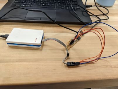
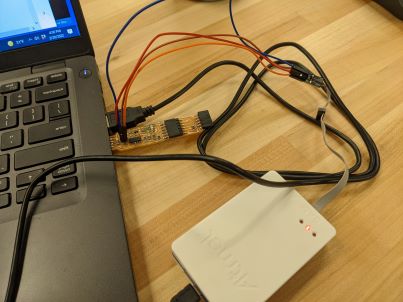
- Burn the bootloader using Jason’s SWD programmer. So you need a programmer to program a programmer…so where did this all start?! Here’s an image of Jason’s programmer:
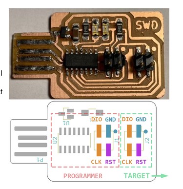
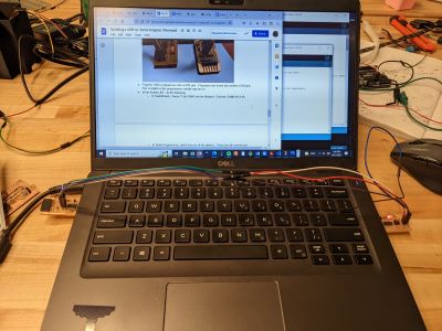
I connected my board to Jason’s board. Then I went to plug them into my computer and the side-by-side USB ports don’t allow for both to be plugged in. Enter more wires and the connection across my computer.
Then I followed the steps from Jason’s doc. I am going to literally copy and paste them here:
In the Arduino IDE, do the following: * In Tools/Board, choose “Fab SAM Core for Arduino” / Generic SAMD11C14A. * In Tools/Programmer, select any one of the options. These are all commercial programmers, and Arduino will auto-detect the SWD programmer I made, but you have to make some choice, or the Arduino app gets confused. * Other settings to check in Tools: Serial config: TWO_UART_NO_WIRE_NO_SPI Bootloader size: 4KB_BOOTLOADER ** In Tools, choose “Burn Bootloader”. You should see a message at the bottom of the window indicating that the chip was programmed and verified. * Unplug the dupont wires, remove both boards from the USB, and plug your new board back in. Bootloading was successful if a new communications port, probably labeled “Generic SAMD11C14A”, appears in the Tools / Port dropdown menu.
Here are the screenshots of the successful bootloading. I’m not sure they tell you much, but here they are;
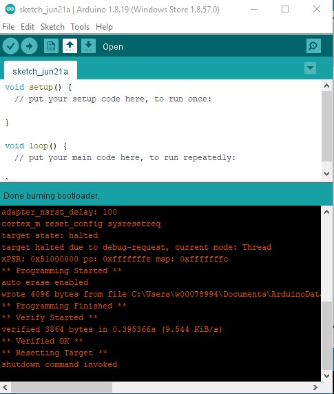
A new port appeared!! It took a couple of minutes and so I thought it had failed again, but it did not.
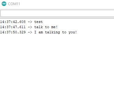
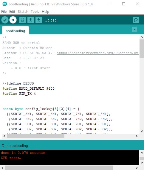
I tested that the board was working by making it talk to itself. You can see evidence of this through the screenshot of the serial monitor below. This is the output when I connect the RX and TX pins to each other from my programmer.